EP0242575A1 - Maschine zur Behandlung von photographischen Filmen - Google Patents
Maschine zur Behandlung von photographischen Filmen Download PDFInfo
- Publication number
- EP0242575A1 EP0242575A1 EP87103623A EP87103623A EP0242575A1 EP 0242575 A1 EP0242575 A1 EP 0242575A1 EP 87103623 A EP87103623 A EP 87103623A EP 87103623 A EP87103623 A EP 87103623A EP 0242575 A1 EP0242575 A1 EP 0242575A1
- Authority
- EP
- European Patent Office
- Prior art keywords
- longitudinal member
- support
- treatment
- films
- movable longitudinal
- Prior art date
- Legal status (The legal status is an assumption and is not a legal conclusion. Google has not performed a legal analysis and makes no representation as to the accuracy of the status listed.)
- Granted
Links
- 238000011282 treatment Methods 0.000 title claims abstract description 83
- 239000000126 substance Substances 0.000 claims abstract description 26
- 230000007723 transport mechanism Effects 0.000 claims abstract description 20
- 238000001035 drying Methods 0.000 claims abstract description 18
- 239000007788 liquid Substances 0.000 claims description 11
- 239000000463 material Substances 0.000 claims description 10
- 210000002105 tongue Anatomy 0.000 claims description 10
- 230000007246 mechanism Effects 0.000 claims description 3
- 230000010355 oscillation Effects 0.000 claims description 3
- 230000000332 continued effect Effects 0.000 claims 1
- 230000001360 synchronised effect Effects 0.000 abstract description 3
- 230000032258 transport Effects 0.000 description 24
- 230000011664 signaling Effects 0.000 description 14
- 230000000694 effects Effects 0.000 description 4
- 239000002253 acid Substances 0.000 description 3
- 230000006641 stabilisation Effects 0.000 description 3
- 238000011105 stabilization Methods 0.000 description 3
- 238000005406 washing Methods 0.000 description 3
- 238000004061 bleaching Methods 0.000 description 2
- 238000005119 centrifugation Methods 0.000 description 2
- 239000012530 fluid Substances 0.000 description 2
- 230000005540 biological transmission Effects 0.000 description 1
- 229910052729 chemical element Inorganic materials 0.000 description 1
- 230000008878 coupling Effects 0.000 description 1
- 238000010168 coupling process Methods 0.000 description 1
- 238000005859 coupling reaction Methods 0.000 description 1
- 230000006378 damage Effects 0.000 description 1
- 230000018109 developmental process Effects 0.000 description 1
- 238000006073 displacement reaction Methods 0.000 description 1
- 238000010981 drying operation Methods 0.000 description 1
- 244000145841 kine Species 0.000 description 1
- 238000004519 manufacturing process Methods 0.000 description 1
- 238000000034 method Methods 0.000 description 1
- 230000035515 penetration Effects 0.000 description 1
- 230000009467 reduction Effects 0.000 description 1
- 230000008929 regeneration Effects 0.000 description 1
- 238000011069 regeneration method Methods 0.000 description 1
- 241000894007 species Species 0.000 description 1
- 210000001050 stape Anatomy 0.000 description 1
Images


Classifications
-
- G—PHYSICS
- G03—PHOTOGRAPHY; CINEMATOGRAPHY; ANALOGOUS TECHNIQUES USING WAVES OTHER THAN OPTICAL WAVES; ELECTROGRAPHY; HOLOGRAPHY
- G03D—APPARATUS FOR PROCESSING EXPOSED PHOTOGRAPHIC MATERIALS; ACCESSORIES THEREFOR
- G03D3/00—Liquid processing apparatus involving immersion; Washing apparatus involving immersion
- G03D3/08—Liquid processing apparatus involving immersion; Washing apparatus involving immersion having progressive mechanical movement of exposed material
- G03D3/10—Liquid processing apparatus involving immersion; Washing apparatus involving immersion having progressive mechanical movement of exposed material for plates, films, or prints held individually
Definitions
- the present invention relates to a machine for the treatment of the photographic films comprising a part for the treatment of the conventional films of per se known and since long time used kind, which is adequately arranged for the application of a new appliance for the treatment of those specific films having a circular disc form, which are commonly called “disc films” and used in a recent tine and which therefore have not been yet widely diffused.
- Such a new appliance performs a normal series of treat ments on the said disc films, which comprise the developing, bleaching, fixing and stabilization, among them adequate washing cycles are interposed, and which terminate with the drying of the photosensitive material.
- a new appliance results to be particularly suitable and expressly conceived to be directly and optionally applied on a con ventioral appliance for the treatment of films for generic uses such as the 35 mm - films and the like, in order to obtain a considerable commercial and economic result.
- the two appliances are completely independent and practically it is foreseen a conventional appliance for the tratment of the usually utilized films and a specific appliance for the treatment of the disc films only, which are reciprocally placed side by side and interconnected in an adequate manner, so as the treatment liquids only of the first appliance will be utilized for the second appliance too.
- the scope of the invention is that to have a maximum rationalization of an entire appliance, which at the same time may perform treatments both of conventional and disc films, with overall dimensions and components thereof which are minimized, so permitting a global cheaper appliance to be obtained.
- Such a machine is characterized in that the tanks containing the chemical baths for the different stages of chemi cal treatment only are shaped with a limited lateral extent in their upper part, which extent is able to receive support elements for the transport of groups of disc films, and in that it may be applied a mechanism on the said lateral extent, if requested, which mechanism is able to transport at least one of the said support ele ments for the transport of group of disc films, from a specific loading box to the outlet towards a collecting container, the said groups of disc films being adequate ly assembled on rotating supports which permit the rotational movement of the discs, requested during the diffe rent treatment stages, to be obtained directly from the already existing movement of the liquid contained within the different treatment tanks and, during the dripping stage, from a suitable air jet; wherein the end drying is finally performed in a suitable container, in which a part of the same hot air which is utilized in the main machine for the developing of conventional films is introduced therein.
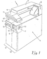
- the main structure of the machine 1 comprises an outer structure constituted by an envelope forming in its inner side a light-proof part, in which the appliances for the treatment of the photosensitive material are disposed.
- the machine 1 comprises a portion S1 (at the left side) and a portion S2 (at the right side) which are placed side by side each other, wherein the portions S1 and S2 respectively permit the treatment of conventional and disc films to be performed.
- the box 12 is provided with a ligh-proof cover 121 at the upper side thereof and additionally a control panel 13 is directly disposed below the loading box 12.
- a further box 14 is projecting towards a back side with respect to the front side referred to, in which inner side there are contained the appliance for the chemical treatments of the conventional films and that one for the chemical treatment of the disc films.
- the box 15 acting for the drying operation of the portion S1 is situated upon the box 14, at the left side thereof, wherein the box 15 is projecting at its back end portion towards the drying box 16 of the portion S2, so forming a "L"-shaped structure as it may be seen.
- the box 17 acting as outlet side of the material which was been treated within the portion S1, wherein the box 17 comprises an angular module 18 for returning such a material, which is able to convey the same material to its right end portion from which the material may coming out for being collected in a suitable manner.
- a box-li ke container 19 which is able to receive a suitable number of support elements S-SR for the transport of the disc films D at the outlet of the said box 16 and at the end of the treatment which has been performed on the respective portion S2 thereof.
- Such box-like container 19 is provided with an adequate door 19a in its upper side, in order to permit the operator to extract therefrom the said support elements for the transport of the disc films, which are storing therein during the operation of the machine.
- Such tanks are reciprocally disposed side-by-side and longitudinally aligned according a conventional successive sion arrangement of the treatment stages, in the follo wing manner: a development tank SV, two bleaching tanks SB, a washing tank L1, two fixing tanks FS, two washing tanks L2, a stabilization tank ST.
- each tank is basically constituted by a first portion forming an envelope 71, having a substantially parallelepiped shape with a rectangular cross-section at the upper side of it a lateral projecting part 72 with a limited height is extending therefrom, in correspondence of one of the shorter sides of the same envelope,wherein the lateral projecting part 72 is joined, on the bottom side thereof, to a wall 73 which is inclined toward the said first portion 71, the whole thus forming a sole basin.
- the said first portion.71 is reserved for the tratment of the conventional films, which will be carried out in a conventional manner and by utilizing per se known appliances, which are neither illustrated nor described for a clear and simple explanation thereof.
- the said second portion 72 is reserved for the treatment of the disc films.
- a transport mechanism TR On the side constituted by the group of the lateral projecting parts of the tanks it is disposed a transport mechanism TR, in order to shift from a tank to another one adequate support elements S on which respective ro tating supports SR for the disc films are applied.
- the support elements S are constituted by a slidable plate 20, from the upper portion of which an arm 21 is orthogonally projecting, which arm is provided near its end portions with two plates 22a and 22b, which are parallel to the said slidable plate 20 and thence between them.
- each plate 22a, 22b near its respective free end portion a slotted hole 23a, 23b is provided, which is able to receive the lateral pins 31a and 31b of the said rotating support SR which will be hereinafter described, wherein the pins are passing through adequate lateral slits which are inclined toward the free end portion of the respective plate 22a, 22b, so permitting the rotating support SR to be rotatable supported by the lower end portions of the said slotted holes 23a, 23b.
- the said rotating support SR may be rotata ble supported on the said support S also in other different manners, equivalent to that one which has been described and to which reference is made.
- the said slidable plate 20 presents a substantially rectangular outline, whose front upper corner 24 (by considering the shifting direction of the support S when it is applied onto the transport device TR) is bevelled in a suitable way for the reasons which will be hereinafter described.
- a notched band 25 is provided at the face of the slidable plate 20 which is opposite to that one from which the arm 21 is exten ding and about at a half lenght of it, practically in correspondence of the zone in which such an arm 21 is extending therefrom, wherein the notched band 25 is extending from the upper to the lower side of the face referred to as well as in a direction which is orthogonal with respect to these sides.
- a longitudinal slot 26 is provided in an axial direction with respect to such a notched band 25.
- the rotating support SR results to be formed by two bladed discoidal elements 30a and 30b, equal each other, each of them is constituted by a disc 301 provided with radial blades 302 on a side thereof and having for obvious reasons, a diameter which is somewhat greater than that one of the disc films D.
- a shaft 31 which presents a lenght slightly greater than the distance resulting between the outer faces of the plates 22, wherein such a shaft 31 is projecting from the face of the relative disc 301, which face isn't provided with radial blades 302, with a short portion constituting the stud 31a.
- a shaft 31 is projecting on the opposite side thereof with a first portion 31c having a suitable diameter, permitting it to be inserted into the central holes of the relative disc films D and a lenght which is sufficient to permit a good number of such disc films D to be applied on it.
- a second portion 31d of such a shaft 31 has a diameter which is somewhat smaller than the first one, and is able to receive removably a second discoidal element 30 b, which is arranged thereon with the relevant bladed portion which is turned toward the inner side of the support SR, (which portion is opposite to that one of the previous discoidal element), wherein the said second portion 31d presents such a lenght that, after the application of the second discoidal element 30b, it results to be protruding from this a bladed portion with a short portion constituting the stud 31b.
- portion 31c is provided with a longitudinal projection 31r able to engage itself with corresponding slots, provided within the central holes of the disc films D so as to prevent the rotation of the same with respect to the shaft 31.
- the so resulting unit (support SR completely assembled) is applied onto the support S by introducing its lateral studs 31a and 31b into the relative slotted holes 23a . and 23b, provided onto the plates 22a and 22b, in which the studs penetrate until they are arranged on the bottom side of the same, so resulting rotatable supported.
- the support and transport element S-SR is thus ready for being utilized.
- Such systems normally require more moving sources (motors) as well as complicated systems for transmitting the movement, having different moving parts-like belts, pulleys, gears, bearing etc. which are operating immersed into the treatment baths, so that these parts must be executed by using particular techniques and suitable materials.
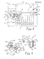
- the liquids contained within the dif ferent treatment tanks are moved by means of respective pumps, so that, as it is provided in the machine referred to and clearly illustrated particularly in the fig. 7, in order to obtain the rotation of the support SR and therefore of the disc films which are disposed thereon, it is sufficient to utilize such a moved liquid coming from the feeding tube 33, by directing it to act against the radial blades 302 of the rotating supports SR, through an adequate nozzle 34 which is disposed and oriented in a suitable manner.
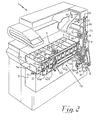
- the rotation thereof may be obtained by means of an air jet which is produced by a simple fan VE and oriented in a suitable manner by a relative nosepiece B (see the fig. 2 and 3).
- the transport of the said support and transport elements S-SR through the different treatment tanks V is obtained by means of a new transport mechanism TR, which is hereinafter described.
- Such a transport mechanism TR is constituted by a first movable longitudinal member 40, which is able to support slidably the said supports S and results to be vertically translatable, by guiding it through adequate vertical guide elements (not shown) and by a second movable longitudinal member 41, which is horizontally translatable by guiding it in a suitable manner and supporting it by the sliding blocks 41a-41b, which are slidably engaged on it and result to be fixed on the fixed longitudinal member 44 by means of the lateral supports 41d-41e, which determine also the adequate arrangement of the same member over the said first movable longitudinal member 40, wherein the said first movable longitudinal member 40 results to be able to shift the said supports S from a first lower position, in which they result to be introduced into a relative treatment tank, to a second upper position in which they result to be completely extracted therefrom.
- the said second longitudinal member 41 results to be able to shift the said supports S, when the same find themselves in a raised condition at the said second upper position, from a tank to another one, over the respective tank.
- the said first movable longitudinal member 40 has a structure with an asymmetric "U" cross-section, so forming in practice a groove with its lower part, in which groove the slidable plate 20 of the supports S may slide, and is provided with some cavities 40a, which permit the guide plates 45 hereinafter descri bed to pass therealong.
- the vertical translation of the said first longitudinal member 40 is obtained by means of two cams 42a and 42b, which are situated near its end portions and on which the said longitudinal member 40 is supported, wherein such cams 42a-42b result to be connected, through respective shafts 42c-42d rotatable supported by the fixed longitudinal member 44, to the toothed pulleys 42e (not shown in fig. 2) and 42f, which are reciprocally interconnected through a toothed belt 42g, so that the movements of the said cams 42a-42b result to be synchronous.
- This group (42r-42s) is that to obtain a resilient accompanying condition of the descent movement of the first movable longitudinal member 40, so as to prevent any too rapid and uncontrolled falling thereof due to the shape of the cams 42a-42b, and the consequent drawbacks caused by the same.
- Such an intermittent crank and slotted link 43 results to be constituted by the rigid rod 43a, which is pivoted at its lower end portion on the fixed longitudinal member 44 by means of the pin 43b, wherein the oscillating movement of the rod 43a is commanded by a.crank, whose crankpin 43d is engaged into the slot 43e provided at an intermedia te portion of the said rigid rod 43a and whose crank arm (not visible in the fig. 2) is fixed to the sprocket wheel 43 g, which receives the intermittent movement of the partial gear wheel 43h, whose toothing is extended for about 1/3 of its circumference only, and which is fixed to the front end portion of the shaft 42c.
- the said rigid rod 43a is provided at its upper end portion with a slot 43i, in which the pin 41c fixed onto the said second longitudinal member 41 is engaged.
- a further pulley 42h which is connected trough the toothed belt 42i to the pulley 42p, which in turn may be driven by the main driving unit 6 by means of the electromagnetic clutch 42m.
- the said fixed longitudinal member 44 results to be fixed to the structure of the group of the tanks V by means of the lateral supports 44a and that onto the longitudinal member 44 there are fixed the guide plates 45, which are reciprocally equally spaced as much as the width of the single tanks and are provided in the same amount as the tanks, wherein such guide plates are located at the level of the transversal axis of each tank and result to be vertically disposed and orthogonally extended from the inner surface of the said fixed longitudinal-member 44 as well as partially protruded from the structure of the said first longitudinal member 40.
- guide plates 45 The function of such guide plates 45 is that to guide the vertical translation of the supports S, which is commanded by the said first longitudinal member 40, which in turn is provided, as already described, with respective cavities 40a in correspondence of each guide plate 45, permitting it to pass therealong during its movements.
- tongues 41p which are also vertically disposed and orthogonally extended as well as turned toward the inner side therefrom, which tongues are reciprocally equally spaced as much as the-said guide plates 45.
- a main driving unit 6 which drives, as it is described in detail hereinafter, all the different kinematic operating devices of both the portions S1 and S2.
- Such a main driving unit 6 comprises a sole motor M which, in its driven condition, by means of an adequate transmission system, reduction gear R, couple of helical gears 51, couple of toothed pulleys 52-53 interconnected by the toothed belt 54, rotatably drives the main shaft 55 which in turn results to be connected to the treatment apparatus of the portion S1, so operating the same directly.
- the gear wheel 56 is assembled onto such a main shaft 55 and is connected by the chain 57 to the gear wheel 58, which is fixed onto the shaft 59, onto which a helical gear 60 engaging itself with the helical gear 61 is also fixed, wherein the helical gear 61 is fixed onto the shaft 62, onto which the toothed pulley 63 is also fixed.
- such a toothed belt 64 acts for translating upwardly the supports 16, contained within the box 16, to which the said supports are coming after the chemical treatments have been effected, as well as acts for carrying these supports at the outlet zone thereof.
- the toothed belt referred to results to be always driven when the apparatus of the portion S1 is operating.
- the shaft 59 is connected by means of the cou ple of gear wheels 66-67 to the electromagnetic clutch 42m, so that the apparatus of the portion S2 i.e. the above described transport mechanism TR thereof will be only operating when such an electromagnetic clutch 42m has been commanded.
- connection element (not shown in the figures refer red to), onto which a crank may be applied for permitting, in the case in which the electrical supply is accidentally switched off, to continue to move manually the whole kine matic operating devices for shifting the photosensitive material under treatment, so as to avoid the destruction thereof.
- connection element between the said connection element and the shaft 55 it is disposed a coupling permitting a driving in a sole direction to be obtained, like an already known freewheel device, which disconnects for obvious reasons the mechanical connection to the part driven by the geared motor M-R.
- the disc films treatment group is applied thereto, it is also provided a buffer battery which is able to feed, in the above mentioned case of electrical supply switching off, the microprocessor which is provided, as it will be hereinafter described, for operating and controlling the cycles and all the other functions of the machine (safety, different signaling, alarm devices, etc.) as well as the electromagnetic clutch 42m.
- the manually operated emergency control may command both the kinematic operating devices for the transport of the conventional films under treatment within the portion S1 and those ones of the trans port mechanism TR of the disc films under treatment within the portion S2.
- the box 11 for the starting. handling of the magazines of the different film kinds also acts for loading the portion S2, so that it will be provided with a suitable lightproof door 11a (see fig. 4), which permits the supports S-SR together with the relative disc films D to be introduced into the re - levant treatment part.
- a movable diaphragm E is disposed on the front wall of the box 16 , in correspondence of the outlet side of the supports S which are coming from the chemical treatment part of the machine and another movable diaphragm U is disposed within the dripping room situated before the drying zone of the machine, in correspondence of the outlet side of the supports S which are coming from the dripping zone thereof.
- a specific microprocessor which is adequately programmed for processing the different signa lings coming from the different command, control,signaling, survey devices as well as positioning devices for different parts, etc.
- micro-switches or similar survey devices
- the operator effects the normal handling, if requested, of the conventional films within the box 11 and then their loading into the respective portion S1.
- the support S is disposed in the so-called "waiting place" PA at the beginning of the treatment apparatus and is ready for the starting of the operating cycle.
- the operator closes the said door 11a by switching off the signaling of the relevant micro-switch T1 and, as soon as he surveys on the control panel that all is in order, since the micro-switch T2 of the waiting place signals that the loading has been effected, starts the operation of the apparatus of the portion S2.
- the starting control operates the electromagnetic clutch 42m (and also the motor M, if the same isn't operating) which connects the apparatus of the transport mechanism TR to the main driving unit 6, so that the cams 42a -42b start to rotate, by shifting the said first movable longitudinal member 40 upwardly and therefore also the support S which has been loaded at the initial part thereof.
- the plate 20 of the support S results to be disengaged from the plate 45 and inserted between two tongues 41p of the said second movable longitudinal member 41.
- the partial gear wheel 43h rotates and as soon as the said cams 42a-42b have sufficiently shifted the said first movable longitudinal member 40 upward, the toothed portion of the said partial gear wheel 43h begins to engage the sprocket wheel 43g, so causing the same to be rotated.
- the crank which is connected to the sprocket wheel 43g causes the rigid rod 43a to be oscillated, which rod in turn operates the said second movable longitudinal member 41, during the first oscillation stage, in such a manner as to shift it forward with respect to the direction in which the treatment is carried out, by a lenght which is equal to the width of a single tank.
- the cams 42a-42b operate the said first longitudinal member 40 downward, so that the support unit S-SR descends and penetrates into the first tank SV, by disengaging it from the tongues 41p and at the same time engaging it with the second guide plate 45, which penetrates in its longitudinal slot 26, so ensuring as described hereinbefore the right arrangement thereof at the centre of the tank SV.
- the rigid rod 43a begins doing the second oscillation stage (in a direction which is opposite than the first one), thus operating the said second movable longitudinal member 41 to come back in its starting position, and at the same time the flat spring 42s engages itself with the protruded part of the cam 42r, so that the remaining down stroke of the longitudinal member 40 results to be controlled and resiliently dampened, by avoiding in this manner an effective dropping movement due to the outline of the cams 42a-42b and therefore the relevant drawbacks thereof.
- the toothed portion of the partial gear wheel 43h disengages itself from the sprocket wheel 43g and at the same time the cam 42a (see fig. 4) actuates the micro-switch T4 which, by means of the microprocessor, switches off the electromagnetic clutch 42m by stopping in this manner the cycle for a time period required by the relative treatment stage and by releasing, in the case of a starting failure of the transport, a suitable alarm signaling.
- the support S actuates the micro-switch T3, at the end of its down stroke, which micro-switch switches off the signaling "occupyed waiting place", always by means of the microprocessor, as well as controls that a suitable increment of developing acid be introduced into the relevant tank SV, so as to compensate the greater request thereof due to the additional disc films and it also changes the stepping time period of the cycles, to adjust the same to the treatment need of the disc films.
- the kinematic operated unit of the transport mechanism TR is ready for repeating another cycle.
- a succession of cycles will be carried out, which cycles permit that the transport of the support unit S-SR through the series of tanks for the chemical treatments be effected, wherein the rotating supports SR contained within these tanks are rotated, as already described, together with the relative disc films D which have been applied on the same, by means of the effect of the liquid which is oriented against the respective bladed discoidal elements 30a-30b and is passing through the nozzles 34, during the stopping periods which are foreseen at the end of each cycle.
- the support unit S-SR When the support unit S-SR reaches the last tank ST, at the end of the relevant stabilization cycle thereof, it is opened the said movable diaphragm E so that the said support unit S-SR is introduced, due to the effect of the transport mechanism TR, into the dripping roon provided within the box 16 and arranged in a manner in which the notched band 25 provided in its plate 20 is disposed side-by-side with respect to the toothed belt 64 and at the same time it actuates the micro-switch T5.
- the movable diaphragm E is operated in its closed position and the fan VE is also operated, for an appropriate time period, by means of the micro-switch T5 and always under the control of the microprocessor.
- such a fan VE generates an air jet which is oriented by the nosepiece B against the radial blades 302 of the rotating support SR, so causing the latter to be rotated.
- the sliding block P is operated in such a manner as to push the upwardly moving portion of the toothed belt 64 against the plate 20 of the support S.
- the toothed belt 64 engages itself with its toothed portions with the corresponding toothed portions of the notched band 25 provided onto the said plate 20, and consequently the support unit S-SR is entrained upward, while being at the same time guided by means of guide elements (not shown), in which the said plate 20 is engaged.
- the support unit S-SR passes through the diaphragm U and automatically opens it, so entering into the upper zone of the box 16 in which circulates the same hot air of the drying zone of the treatment portion S1, which air is drawn from such a drying zone and blown into the said drying zone of the treatment portion S2 of the disc films D, by means of a fan (not shown) which is placed on the wall which divides the two drying zones.
- the movable diaphragms E and U are synchronized each other, in such a manner that when a diaphragm is open, the other one is certainly closed.
- the movable diaphragm E is always operated in an opened position by the cam 42b at the end of each operating cycle, still remaining open for the whole stop ping time period of the cycle.
- the unit S-SR is passing through the diaphragm U only when the movable diaphragm E becomes closed, at an operating sequence which is normally foreseen.
- the support unit S-SR continues its stroke until it comes in correspondence of the upper end portion of the toothed belt 64 (pulley 65), where it automatically disengages itself from the latter while remaining practically in a still position, and in this position it actuates the micro-switch T6 which, after an appropriate time period always determined by the said microprocessor, permits a suitable acoustic (and/or luminous) signaling to be released, in-order to inform the operator that this unit must be drawn.
- the micro-switch T7 is located, whose control lever is shifted during the passage of each single support unit S-SR, so comingnadok sudden in its starting position, and this operation is repeated until the same box-like container 19 has been filled (in the machine referred to a storage of three support units S-SR is foreseen), wherein the last of the support units S-SR keeps such a lever in a deviated position, so that after a tine period determined by the microprocessor it operates a suitable acoustic (or eventually luminous too) alarm signaling, which informs the operator that the units S-SR stored within the said box-like container may be extracted therefrom, by opening the door 19a.
- the recirculation cf the liquids for the chemical treatments toward the respective tanks is already arranged, in a manner that it acts against the rotating supports SR, onto which the disc films D to be treated are dispo sed, in order to produce the requested rotational movement thereof.
- the system which is used for rotating the disc films D results to be very simple and reliable, so that any complicated mechanical connection among the supports of the said disc films D to be rotated and the outer driving sources can be avoided.
- the transport unit TR of the disc films D does not require an autonomous driving source, since it may be simply interconnected to the main driving unit 6 which has been already provided for the base structure. It is well understood that different embodiments of the machine referred to may be produced, however without departing from what it has been described and hereinafter claimed, with reference to the enclosed drawings and therefore pertaining to the protection field of the present industrial invention.
Landscapes
- Physics & Mathematics (AREA)
- General Physics & Mathematics (AREA)
- Photographic Processing Devices Using Wet Methods (AREA)
Applications Claiming Priority (2)
| Application Number | Priority Date | Filing Date | Title |
|---|---|---|---|
| IT4571386 | 1986-03-24 | ||
| IT45713/86A IT1191527B (it) | 1986-03-24 | 1986-03-24 | Macchina per il trattamento di pellicole fotografiche |
Publications (2)
| Publication Number | Publication Date |
|---|---|
| EP0242575A1 true EP0242575A1 (de) | 1987-10-28 |
| EP0242575B1 EP0242575B1 (de) | 1991-02-20 |
Family
ID=11257553
Family Applications (1)
| Application Number | Title | Priority Date | Filing Date |
|---|---|---|---|
| EP87103623A Expired EP0242575B1 (de) | 1986-03-24 | 1987-03-12 | Maschine zur Behandlung von photographischen Filmen |
Country Status (6)
| Country | Link |
|---|---|
| US (1) | US4771306A (de) |
| EP (1) | EP0242575B1 (de) |
| JP (1) | JPS62284357A (de) |
| DE (1) | DE3768042D1 (de) |
| DK (1) | DK141587A (de) |
| IT (1) | IT1191527B (de) |
Cited By (2)
| Publication number | Priority date | Publication date | Assignee | Title |
|---|---|---|---|---|
| EP0327260A3 (de) * | 1988-01-30 | 1990-06-13 | Konica Corporation | Automatische Entwicklungsmaschine für Diskfilme |
| CN106154734A (zh) * | 2016-09-14 | 2016-11-23 | 上海应用技术大学 | 一种便携式胶片架干燥装置 |
Families Citing this family (1)
| Publication number | Priority date | Publication date | Assignee | Title |
|---|---|---|---|---|
| USD321201S (en) | 1988-07-18 | 1991-10-29 | Kis Photo Industrie | Photographic film and print developer |
Citations (2)
| Publication number | Priority date | Publication date | Assignee | Title |
|---|---|---|---|---|
| FR2526967A1 (fr) * | 1982-05-17 | 1983-11-18 | Noritsu Kenkyu Center Co | Appareil pour traiter la matiere photosensible sous la forme de films plats |
| DE3233531A1 (de) * | 1982-09-10 | 1984-03-15 | Sitte, Ernst-Adolf, 3250 Hameln | Disc-film-entwicklungsmaschine mit duesenantrieb |
Family Cites Families (7)
| Publication number | Priority date | Publication date | Assignee | Title |
|---|---|---|---|---|
| US4112452A (en) * | 1977-03-07 | 1978-09-05 | Eastman Kodak Company | Apparatus for processing photographic film |
| US4178091A (en) * | 1977-03-07 | 1979-12-11 | Eastman Kodak Company | Horizontal film processing apparatus |
| US4252430A (en) * | 1979-10-12 | 1981-02-24 | Eastman Kodak Company | Film processing apparatus |
| JPS5937542A (ja) * | 1982-08-27 | 1984-03-01 | Konishiroku Photo Ind Co Ltd | フイルム自動現像装置 |
| US4456355A (en) * | 1982-10-05 | 1984-06-26 | Pako Corporation | Control apparatus for film disc processor |
| US4575209A (en) * | 1984-05-22 | 1986-03-11 | Houston Fearless 76, Inc | Disc film processor |
| JPS61160442U (de) * | 1985-03-26 | 1986-10-04 |
-
1986
- 1986-03-24 IT IT45713/86A patent/IT1191527B/it active
-
1987
- 1987-03-12 DE DE8787103623T patent/DE3768042D1/de not_active Expired - Fee Related
- 1987-03-12 EP EP87103623A patent/EP0242575B1/de not_active Expired
- 1987-03-19 US US07/027,822 patent/US4771306A/en not_active Expired - Fee Related
- 1987-03-19 DK DK141587A patent/DK141587A/da not_active Application Discontinuation
- 1987-03-24 JP JP62070126A patent/JPS62284357A/ja active Pending
Patent Citations (2)
| Publication number | Priority date | Publication date | Assignee | Title |
|---|---|---|---|---|
| FR2526967A1 (fr) * | 1982-05-17 | 1983-11-18 | Noritsu Kenkyu Center Co | Appareil pour traiter la matiere photosensible sous la forme de films plats |
| DE3233531A1 (de) * | 1982-09-10 | 1984-03-15 | Sitte, Ernst-Adolf, 3250 Hameln | Disc-film-entwicklungsmaschine mit duesenantrieb |
Non-Patent Citations (1)
| Title |
|---|
| PATENT ABSTRACTS OF JAPAN, vol. 8, no. 137 (P-282)[1574], 26th June 1984; & JP-A-59 37 542 (KONISHIROKU SHASHIN KOGYO K.K.) 01-03-1984 * |
Cited By (2)
| Publication number | Priority date | Publication date | Assignee | Title |
|---|---|---|---|---|
| EP0327260A3 (de) * | 1988-01-30 | 1990-06-13 | Konica Corporation | Automatische Entwicklungsmaschine für Diskfilme |
| CN106154734A (zh) * | 2016-09-14 | 2016-11-23 | 上海应用技术大学 | 一种便携式胶片架干燥装置 |
Also Published As
| Publication number | Publication date |
|---|---|
| IT8645713A0 (it) | 1986-03-24 |
| DK141587D0 (da) | 1987-03-19 |
| DK141587A (da) | 1987-09-25 |
| JPS62284357A (ja) | 1987-12-10 |
| US4771306A (en) | 1988-09-13 |
| DE3768042D1 (de) | 1991-03-28 |
| EP0242575B1 (de) | 1991-02-20 |
| IT1191527B (it) | 1988-03-23 |
Similar Documents
| Publication | Publication Date | Title |
|---|---|---|
| EP0157214B1 (de) | Entwicklungsgerät | |
| US4553406A (en) | Device for storing and automatic drawing of so-called intermediate elements, for loading, feeding and discharge of certain products, from a freezer to horizontal plates | |
| EP0242575A1 (de) | Maschine zur Behandlung von photographischen Filmen | |
| US3712206A (en) | Chip film processor | |
| US2770179A (en) | Apparatus for processing strips of light-sensitive material | |
| EP0242817A1 (de) | Filmzuführvorrichtung | |
| JP2640520B2 (ja) | 写真感光材料の処理方法及び処理機 | |
| US3559553A (en) | Automatic forwarding mechanism for photographic materials | |
| EP0327084B1 (de) | Filmentwicklungseinsatz und Tank | |
| US2157128A (en) | Photographic developing machine | |
| US2823595A (en) | Photographic processing machine | |
| US3343472A (en) | Photographic processing machine | |
| US3886575A (en) | Apparatus for treating photographic material in closed cassettes | |
| US3683781A (en) | Automatic processor | |
| US3739706A (en) | Photographic processor | |
| US4130825A (en) | Apparatus for automatically treating pieces of exposed photosensitive paper | |
| US4003512A (en) | Apparatus for sequentially and simultaneously driving plural pairs of feed rollers | |
| KR100265157B1 (ko) | 칩 부품 공급장치 | |
| US4572639A (en) | Film processing apparatus including a control system | |
| US5241339A (en) | Film processor for X-ray film | |
| US2475658A (en) | Photographic developing apparatus with easily accessible tanks and conveyers | |
| US3722384A (en) | Automatic coin or token operated apparatus for taking and developing photographs | |
| US3901253A (en) | Film processor chemical supply mechanism | |
| US4760416A (en) | Wet processing arrangement for photosensitive articles | |
| US4764792A (en) | Copying machine with modular original document light-image forming device |
Legal Events
| Date | Code | Title | Description |
|---|---|---|---|
| PUAI | Public reference made under article 153(3) epc to a published international application that has entered the european phase |
Free format text: ORIGINAL CODE: 0009012 |
|
| AK | Designated contracting states |
Kind code of ref document: A1 Designated state(s): CH DE ES FR GB IT LI |
|
| 17P | Request for examination filed |
Effective date: 19871022 |
|
| 17Q | First examination report despatched |
Effective date: 19891229 |
|
| GRAA | (expected) grant |
Free format text: ORIGINAL CODE: 0009210 |
|
| AK | Designated contracting states |
Kind code of ref document: B1 Designated state(s): CH DE ES FR GB IT LI |
|
| PG25 | Lapsed in a contracting state [announced via postgrant information from national office to epo] |
Ref country code: IT Free format text: LAPSE BECAUSE OF FAILURE TO SUBMIT A TRANSLATION OF THE DESCRIPTION OR TO PAY THE FEE WITHIN THE PRE;WARNING: LAPSES OF ITALIAN PATENTS WITH EFFECTIVE DATE BEFORE 2007 MAY HAVE OCCURRED AT ANY TIME BEFORE 2007. THE CORRECT EFFECTIVE DATE MAY BE DIFFERENT FROM THE ONE RECORDED.SCRIBED TIME-LIMIT Effective date: 19910220 Ref country code: FR Effective date: 19910220 Ref country code: LI Effective date: 19910220 Ref country code: CH Effective date: 19910220 |
|
| REF | Corresponds to: |
Ref document number: 3768042 Country of ref document: DE Date of ref document: 19910328 |
|
| PG25 | Lapsed in a contracting state [announced via postgrant information from national office to epo] |
Ref country code: GB Effective date: 19910520 |
|
| PG25 | Lapsed in a contracting state [announced via postgrant information from national office to epo] |
Ref country code: ES Free format text: LAPSE BECAUSE OF FAILURE TO SUBMIT A TRANSLATION OF THE DESCRIPTION OR TO PAY THE FEE WITHIN THE PRESCRIBED TIME-LIMIT Effective date: 19910531 |
|
| REG | Reference to a national code |
Ref country code: CH Ref legal event code: PL |
|
| EN | Fr: translation not filed | ||
| PLBE | No opposition filed within time limit |
Free format text: ORIGINAL CODE: 0009261 |
|
| STAA | Information on the status of an ep patent application or granted ep patent |
Free format text: STATUS: NO OPPOSITION FILED WITHIN TIME LIMIT |
|
| PG25 | Lapsed in a contracting state [announced via postgrant information from national office to epo] |
Ref country code: DE Effective date: 19920101 |
|
| GBPC | Gb: european patent ceased through non-payment of renewal fee | ||
| 26N | No opposition filed |