EP0242258A1 - Device for the execution of an algorithm (Leroux-Gueguen) for the coding of a signal by linear prediction - Google Patents
Device for the execution of an algorithm (Leroux-Gueguen) for the coding of a signal by linear prediction Download PDFInfo
- Publication number
- EP0242258A1 EP0242258A1 EP87400669A EP87400669A EP0242258A1 EP 0242258 A1 EP0242258 A1 EP 0242258A1 EP 87400669 A EP87400669 A EP 87400669A EP 87400669 A EP87400669 A EP 87400669A EP 0242258 A1 EP0242258 A1 EP 0242258A1
- Authority
- EP
- European Patent Office
- Prior art keywords
- output
- input
- register
- rank
- coefficients
- Prior art date
- Legal status (The legal status is an assumption and is not a legal conclusion. Google has not performed a legal analysis and makes no representation as to the accuracy of the status listed.)
- Granted
Links
Images
Classifications
-
- G—PHYSICS
- G06—COMPUTING; CALCULATING OR COUNTING
- G06F—ELECTRIC DIGITAL DATA PROCESSING
- G06F17/00—Digital computing or data processing equipment or methods, specially adapted for specific functions
- G06F17/10—Complex mathematical operations
- G06F17/15—Correlation function computation including computation of convolution operations
-
- G—PHYSICS
- G10—MUSICAL INSTRUMENTS; ACOUSTICS
- G10L—SPEECH ANALYSIS OR SYNTHESIS; SPEECH RECOGNITION; SPEECH OR VOICE PROCESSING; SPEECH OR AUDIO CODING OR DECODING
- G10L25/00—Speech or voice analysis techniques not restricted to a single one of groups G10L15/00 - G10L21/00
Definitions
- the present invention relates to a device for implementing an algorithm called LEROUX-GUEGUEN, for coding a signal by linear prediction.
- the invention applies to the processing of very varied signals (seismic, biological, speech, radar, telephone signals, etc.).
- the nonlinear transformation which makes it possible to obtain the partial correlation coefficients Kj from the correlation coefficients R; is performed using an algorithm known as the LEROUX-GUEGUEN algorithm.
- the object of the invention is to remedy the drawbacks of existing devices, making it possible to implement the LEROUX-GUEGEN algorithm, for coding a signal by linear prediction.
- the invention makes it possible in particular to obtain a device which can be constituted in the form of a single integrated circuit (or part of a circuit), of small surface area, inexpensive, requiring no treatment program.
- the partial correlation coefficients will be called, in a known manner, PARCOR coefficients.
- the subject of the invention is a device for implementing a so-called LEROUX-GUEGUEN algorithm for coding a signal by linear prediction, this device receiving on an input, coefficients R; of correlation of the sampled signal, and providing on an output partial correlation coefficients K f , called PARCOR, i being an integer varying from 1 to a predetermined number p of coefficients, characterized in that it comprises 2p shift registers, connected according to a ring, so that an output of a register of rank 1 + 1 is connected to the input of a register of rank i, an input of the register of rank 2p being connected to an output of the register of rank 1 , a first multiplexer whose input and output connect the output of the rank 1 register to the input of the rank 2p register, another input of this first multiplexer constituting the input of the device receiving correlation coefficients R i , a second multiplexer, an input and an output of which connect the output of the rank 2p register to the input of the rank register 2p-1, a
- the device receives on an input 1 coefficients Ri of correlation or of modeling of a sampled signal. It provides on an output 2, coefficients K; of partial correlation also called PARCOR coefficients.
- the index i is a whole number varying from 1 to a predetermined number p of coefficients.
- the device includes 2p shift registers, with serial input and output.
- These registers are connected in series according to a ring, so that the output of the register of rank i + 1 is connected to the input of the register of rank i.
- the input of the rank register 2p is connected to the output of the rank register 1
- the input of the rank register 8 is connected to the output of the rank register 1.
- Another input 5 of this first multiplexer constitutes the input of the device receiving the correlation coefficients Ri.
- the device also includes a second multiplexer MUX2 of which an input 6 and an output 7 connect the output of the rank register 2p (register X8 in the example considered), to the input of the rank register 2p - 1 (register X7 on the figure).
- MUX2 of which an input 6 and an output 7 connect the output of the rank register 2p (register X8 in the example considered), to the input of the rank register 2p - 1 (register X7 on the figure).
- the outputs 4, 7 of the first and second multiplexers are respectively connected to the inputs of a series D divider.
- the output 10 of this divider constitutes the output of the device, which provides the coefficient Ki PARCO.
- An output 17 of the first adder A1 is connected to an input 18 of the first multiplexer MUX1.
- An output 22 of the second multiplier is connected to an input 23 of a second adder A2.
- Another input 24 of this second adder is connected to output 25 of the rank 2p register (register X8 in the example considered).
- An output 26 of the second adder A2 is connected to an input 27 of the second multiplexer MUX2.
- the device comprises sequencing means S having control outputs connected respectively to control inputs 28, 29, 30, 31, 32, first and second multipliers M1, M2 and first and second multiplexers MUX1 and MUX2 and of the divider D.
- sequencing means S having control outputs connected respectively to control inputs 28, 29, 30, 31, 32, first and second multipliers M1, M2 and first and second multiplexers MUX1 and MUX2 and of the divider D.
- the operation of the device and the role of the sequencing means S will be described later in detail.
- the registers, multiplexers, adders, as well as the divider, are not shown in detail in the figure since these components are well known in the state of the art.
- Multipliers M1, M2 can be of a type described in the article entitled "Circuits for Digital Signal Processing" by H.BARRAL and N.MOREAU - ICASSP84, San Diego - March 1984.
- the intermediate variables I, E used in the LEROUX-GUEGUEN algorithm are obtained by processing the correlation coefficients Ri, by successive iterations performed by the device, as shown in Table 1.
- Part A of this table provides a better understanding of the initialization of the device from the Ri values going from R o to Rp, (that is to say from Ro to R 4 in the embodiment considered).
- -1 correspond respectively to the correlation coefficients R o ... Rp- 1 .
- the first intermediate variables E 1 ... E correspond respectively to the correlation coefficients R 1 ... Rp.
- the initialization of the device therefore consists of loading these first intermediate variables into the corresponding registers. This operation is carried out by applying the successive values R o ... Rp to the input 1 of the device and by applying control signals from the sequencing means S. to the control inputs 30, 31 of the multiplexers MUX1, MUX2. sequencing as well as the loading of the corresponding registers appears in table 2.
- the device which comprises eight registers makes it possible to obtain four PARCOR coefficients K 1 , K 2 , ... K 4 , from five correlation coefficients Ro ... R 4 .
- binary values representative of the first correlation coefficient Ro are again applied to the input 1 of the multiplexer MUX1. These bits are applied to the serial input of the X8 register which transfers its content (R o ) to the X7 register.
- control signals are applied to the control inputs 31, 32 of the multi plexers MUX1, MUX2 by the sequencing means S. It follows that at time T i , the registers X8 and X7 are loaded respectively by binary elements corresponding to the first correlation coefficient R 0 .
- registers X1 and X8 are at time T 7 loaded by the correlation coefficients Ro ... R 3 as indicated in column T 7 of table 2.
- the values corresponding to the coefficient of correlation R 4 are applied to the input of the register X8 thus operating an additional shift of the content of the registers.
- the correlation coefficients whose values are loaded inside the registers are indicated in column T a of table 2.
- -1 and E ... E are obtained by carrying out the multiplication and addition operations indicated in part B of table 1.
- summer is carried out as follows.
- the intermediate variable E is available depending on the output of register X2.
- the intermediate variable I 8 is available on the output of register X8 at time Ts. It is therefore possible to calculate thanks to the multipliers M2 with the adder A2 the new intermediate variable
- Table 3 gives an intermediate calculation to be carried out by the adders, the multipliers, as well as the divider, to calculate the PARCOR coefficients Ki, K 2 , K 3 , K 4 in the embodiment considered.
Abstract
L'invention concerne un dispositif de mise en oeuvre d'un algorithme dit de LEROUX-GUEGUEN, pour le codage d'un signal par prédiction linéaire.The invention relates to a device for implementing a so-called LEROUX-GUEGUEN algorithm for coding a signal by linear prediction.
Ce dispositif reçoit sur une entrée (1) des coefficients Ri de corrélation du signal échantillonné, et fournit sur une sortie (2) des coefficients Kide corrélation partiels dits PARCOR. Le dispositif comprend un anneau de registres à décalages (X1...X8), deux multiplexeurs (MUX1, MUX2), deux multiplieurs (M1, M2), deux additionneurs (A1, A2) et un diviseur (D) qui calculent par des itérations successives des variables intermédiaires permettant de passer des coefficients de corrélation Ri, aux coefficients PARCOR Ki.This device receives on an input (1) coefficients R i of correlation of the sampled signal, and supplies on an output (2) partial correlation Kide coefficients called PARCOR. The device comprises a ring of shift registers (X1 ... X8), two multiplexers (MUX1, MUX2), two multipliers (M1, M2), two adders (A1, A2) and a divider (D) which calculate by successive iterations of the intermediate variables making it possible to pass from the correlation coefficients Ri, to the PARCOR coefficients K i .
Application au codage de signaux pour leur transmission.
Description
La présente invention concerne un dispositif de mise en oeuvre d'un algorithme dit de LEROUX-GUEGUEN, pour le codage d'un signal par prédiction linéaire.The present invention relates to a device for implementing an algorithm called LEROUX-GUEGUEN, for coding a signal by linear prediction.
L'invention s'applique aux traitements de signaux très variés (signaux sismiques, biologiques, de parole, radars, téléphoniques, ...).The invention applies to the processing of very varied signals (seismic, biological, speech, radar, telephone signals, etc.).
Dans la transmission d'un signal téléphonique par exemple, à faible débit, il est souhaitable de représenter le signal de parole sous une forme très condensée qui permette néanmoins de conserver une bonne intelligibilité de la parole à la réception de ce signal condensé. Pour cela, on chercheà créer un signal synthétique le plus ressemblant possible au signal original, grâce à une technique de modélisation dite de codage par prédiction linéaire. Ce codage est effectué de la manière suivante :
- le signal est échantillonné à une fréquence constante. A partir des échantillons pris sur une durée pour laquelle on suppose que les caractéristiques statistiques du signal restent constantes, on calcule des coefficients R; de corrélation du signal échantillonné. i est un nombre entier variant de 0 à 10 par exemple. Ces coefficients permettent d'obtenir une condensation importante des informations caractéristiques du signal. Ces coefficients de corrélation donnent un bon modèle de représentation du signal original. Les coefficients de corrélaton R;, ainsi que leur obtention sont décrits dans l'article "Single Chip LPC Vocoder" de Stephen P.Pope et al paru dans (EEE Intemational Solid State Circuits Conference - pages 118 et 119 - 22 Février 1984.
- the signal is sampled at a constant frequency. From the samples taken over a period for which it is assumed that the statistical characteristics of the signal remain constant, coefficients R are calculated; correlation of the sampled signal. i is an integer varying from 0 to 10 for example. These coefficients make it possible to obtain a significant condensation of the information characteristic of the signal. These correlation coefficients give a good model for representing the original signal. The correlation coefficients R;, as well as their obtaining are described in the article "Single Chip LPC Vocoder" by Stephen P. Pope et al published in (EEE Intemational Solid State Circuits Conference - pages 118 and 119 - February 22, 1984.
On sait également qu'après avoir calculé ces coefficients de corrélation, il est ensuite nécessaire d'effectuer une transformation non linéaire de ces coefficients vers d'autres coefficients Kjdits "coefficients de corrélation partiels", qui possèdent de meilleures propriétés de sensibilité, de classification, de codage, ... etc. Ces coefficients sont aussi appelés coefficients PARCOR.We also know that after having calculated these correlation coefficients, it is then necessary to carry out a non-linear transformation of these coefficients towards other coefficients Kj says "partial correlation coefficients", which have better properties of sensitivity, classification , coding, ... etc. These coefficients are also called PARCOR coefficients.
La transformation non linéaire qui permet d'obtenir les coefficients de corrélation partiels Kjà partir des coefficients de corrélation R; est effectuée grâce un algorithme connu sous le nom d'algorithme de LEROUX-GUEGUEN.The nonlinear transformation which makes it possible to obtain the partial correlation coefficients Kj from the correlation coefficients R; is performed using an algorithm known as the LEROUX-GUEGUEN algorithm.
L'algorithme de LEROUX-GUEGUEN est décrit dans un article intitulé "A fixed point computation of partial correlation coefficients" de J.LEROUX et C.GUEGUEN paru dans la revue IEEE Transactions on ASSP - June 1977.The LEROUX-GUEGUEN algorithm is described in an article entitled "A fixed point computation of partial correlation coefficients" by J.LEROUX and C.GUEGUEN published in the journal IEEE Transactions on ASSP - June 1977.
Les dispositifs connus qui permettent de mettre en oeuvre l'algorithme de LEROUX-GUEGUEN pour obtenir les coefficients de corrélation partiels, à partir des coefficients de corrélation d'un signal, utilisent généralement des processeurs associés à des mémoires ainsi que des additionneurs, multiplieurs, ... etc. Ces dispositifs présentent une architecture compliquée ; ils nécessitent des programmes de traitements pour l'obtention des coefficients de corrélation partiels. Ces dispositifs ne peuvent en aucun cas constituer un circuit intégré unique et de faible dimension. Généralement, ces dispositifs occupent une surface importante et les composants qui les constituent peuvent occuper plusieurs cartes.Known devices which make it possible to implement the LEROUX-GUEGUEN algorithm to obtain the partial correlation coefficients, from the correlation coefficients of a signal, generally use processors associated with memories as well as adders, multipliers, ... etc. These devices have a complicated architecture; they require treatment programs to obtain the partial correlation coefficients. These devices can in no case constitute a single integrated circuit of small size. Generally, these devices occupy a large area and the components which constitute them can occupy several cards.
L'invention a pour but de remédier aux inconvénients des dispositifs existants, permettant de mettre en oeuvre l'algorithme de LEROUX-GUEGEN, pour le codage d'un signal par prédiction linéaire. L'invention permet notamment d'obtenir un dispositif qui peut être constitué sous forme d'un circuit intégré unique (ou partie de circuit), de faible surface, peu coûteux, ne nécessitant aucun programme de traitement. Dans la suite de la description, les coefficients de corrélation partiels seront appelés, de façon connue, coefficients PARCOR.The object of the invention is to remedy the drawbacks of existing devices, making it possible to implement the LEROUX-GUEGEN algorithm, for coding a signal by linear prediction. The invention makes it possible in particular to obtain a device which can be constituted in the form of a single integrated circuit (or part of a circuit), of small surface area, inexpensive, requiring no treatment program. In the following description, the partial correlation coefficients will be called, in a known manner, PARCOR coefficients.
L'invention a pour objet un dispositif de mise en oeuvre d'un algorithme dit de LEROUX-GUEGUEN pour le codage d'un signal par prédiction linéaire, ce dispositif recevant sur une entrée, des coefficients R; de corrélation du signal échantillonné, et fournissant sur une sortie des coefficients Kfde corrélation partiels, dits PARCOR, i étant un entier variant de 1 à un nombre p prédéterminé de coefficients, caractérisé en ce qu'il comporte 2p registres à décalage, reliés selon un anneau, de sorte qu'une sortie d'un registre de rang 1 + 1 soit reliée à l'entrée d'un registre de rang i, une entrée du registre de rang 2p étant reliée à une sortie du registre de rang 1, un premier multiplexeur dont une entrée et une sortie relient la sortie du registre de rang 1 à l'entrée du registre de rang 2p, une autre entrée de ce premier multiplexeur constituant l'entrée du dispositif recevant des coefficients de corrélation Ri, un deuxième multiplexeur dont une entrée et une sortie relient la sortie du registre de rang 2p à l'entrée du registre de rang 2p-1, un diviseur dont une entrée est reliée à la sortie du premier multiplexeur et dont une autre entrée est reliée à la sortie du deuxième multiplexeur, une sortie de ce diviseur constituant la sortie du dispositif fournissant les coefficients Ki PARCOR, un premier multiplieur dont une entrée est reliée à une sortie du registre de rang 3 et dont une autre entrée est reliée à la sortie du diviseur, un premier additionneur dont une entrée est reliée à une sortie du premier multiplieur et dont une autre entrée est reliée à la sortie du registre de rang 3, une sortie de ce premier additionneur étant reliée à une entrée du premier multiplexeur, un deuxième multiplieur dont une entrée est reliée à la sortie du registre de rang 2 et dont une autre entrée est reliée à la sortie du diviseur, un deuxième additionneur dont une entrée est reliée à une sortie du deuxième multiplieur et dont une autre entrée est reliée à la sortie du registre de rang 2p, une sortie de l'additionneur étant reliée à une entrée du deuxième multiplexeur, et des moyens de séquencement ayant des sorties de commande reliées à des entrées de commande des premier et deuxième multiplieurs et, des premier et deuxième multiplexeurs et du diviseur, pour commander l'initialisation du dispositif par chargement des coefficients de modélisation Ri dans les registres sous forme de premières variables intermédiaires " ![]()
![]()
![]()
![]()
![]()
![]()
![]()
![]()
![]()
![]()
![]()
![]()
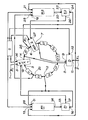
Les caractéristiques et avantages de l'invention ressortiront mieux de la description qui va suivre donnée en référence à la figure annexée qui représente schématiquement un dispositif de mise en oeuvre d'un algorithme de LEROUX-GUEGUEN, conforme à l'invention.The characteristics and advantages of the invention will emerge more clearly from the description which follows given with reference to the appended figure which schematically represents a device for implementing a LEROUX-GUEGUEN algorithm, in accordance with the invention.
Cette description est donnée en exemple pour une architecture de registre série-série. Une architecture parallèle n'entraînerait que quelques modifications mineures.This description is given as an example for a series-series register architecture. Parallel architecture would only involve a few minor modifications.
Le dispositif reçoit sur une entrée 1 des coefficients Ri de corrélation ou de modélisation d'un signal échantillonné. Il fournit sur une sortie 2, des coefficients K; de corrélation partiels encore appelés coefficients PARCOR. L'indice i est un nombre entier vavariant de 1 à un nombre p prédéterminé de coefficients.The device receives on an input 1 coefficients Ri of correlation or of modeling of a sampled signal. It provides on an
Le dispositif comporte 2p registres à décalage, à entrée et sortie série. Dans l'exemple de réalisation représenté sur cette figure p = 4 et le dispositif comprend 2 x 4 = 8 registres à décalage représentés en X1, X2, X3, X4, X5, X6, X7, X8. Ces registres sont reliés en série selon anneau, de sorte que la sortie du registre de rang i + 1 soit reliée à l'entrée du registre de rang i. Par exemple, sur cette figure, la sortie du registre de rang i + 1 = 5 est reliée à l'entrée du registre de rang i = 4. L'entrée du registre de rang 2p est reliée à la sortie du registre de rang 1. Dans l'exemple représenté sur cette figure, l'entrée du registre de rang 8 est reliée à la sortie du registre de rang 1. Le dispositif comprend aussi unn premier multiplexeur MUX1 dont une entrée 3 et une sortie 4 relient la sortie du registre X1 de rang 1, à l'entrée du registre X8 de rang 2p = 8, dans l'exemple représenté sur cette figure. Une autre entrée 5 de ce premier multiplexeur constitue l'entrée du dispositif recevant les coefficients de corrélation Ri.The device includes 2p shift registers, with serial input and output. In the embodiment shown in this figure p = 4 and the device comprises 2 x 4 = 8 shift registers represented at X1, X2, X3, X4, X5, X6, X7, X8. These registers are connected in series according to a ring, so that the output of the register of rank i + 1 is connected to the input of the register of rank i. For example, in this figure, the output of the rank register i + 1 = 5 is connected to the input of the rank register i = 4. The input of the rank register 2p is connected to the output of the rank register 1 In the example represented in this figure, the input of the rank register 8 is connected to the output of the rank register 1. The device also comprises a first multiplexer MUX1 of which an
Le dispositif comprend aussi un deuxième multiplexeur MUX2 dont une entrée 6 et une sortie 7 relient la sortie du registre de rang 2p (registre X8 dans l'exemple considéré), à l'entrée du registre de rang 2p - 1 (registre X7 sur la figure).The device also includes a second multiplexer MUX2 of which an input 6 and an output 7 connect the output of the rank register 2p (register X8 in the example considered), to the input of the rank register 2p - 1 (register X7 on the figure).
Les sorties 4, 7 des premier et deuxième multiplexeurs sont respectivement reliées aux entres d'un diviseur série D. La sortie 10 de ce diviseur constitue la sortie du dispositif, qui fournit le coefficient Ki PARCO.The
Le dispositif comprend aussi un premier multiplieur M1 dont une entrée 11 est reliée à une sortie 12 du registre X3 de rang i = 3. Une autre entrée 13 de ce premier multiplieur est reliée à la sortie 10 du diviseur D.The device also includes a first multiplier M1, an
Une sortie 14 du premier multiplieur M1 est reliée à une entrée 15 d'un premier additionneur A1, dont une autre entrée 16 est relié à la sortie 12 du registre X3 de rang i = 3. Une sortie 17 du premier additionneur A1 est reliée à une entrée 18 du premier multiplexeur MUX1.An
Le dispositif comprend aussi un deuxième multiplieur M2 dont une entrée 19 est reliée à la sortie 20 registre X2 de rang i = 2. Une autre entrée 21 du deuxième multiplieur M2, est reliée la sortie 10 du diviseur D.The device also includes a second multiplier M2, an
Une sortie 22 du deuxième multiplieur est reliée à une entrée 23 d'un deuxième additionneur A2. Une autre entrée 24 de ce dexième additionneur est relliée à la sortie 25 du registre de rang 2p (registre X8 dans l'exemple considéré). Une sortie 26 du deuxième additionneur A2 est reliée à une entrée 27 du deuxième multiplexeur MUX2.An
Enfin, le dispositif comprend des moyens de séquencement S ayant des sorties de commande reliées respectivement à des entrées de commande 28,29,30,31,32, des premier et deuxième multiplieurs M1, M2 et des premier et deuxième multiplexeurs MUX1 et MUX2 et du diviseur D. Le fonctionnement du dispositif et le rôle des moyens de séquencement S seront décrits plus loin en détail. Les registres, multiplexeurs, additionneurs, ainsi que le diviseur, ne sont pas représentés de manière détaillée sur la figure puisque ces composants sont bien connus dans l'état de la technique. Les multiplieurs M1, M2 peuvent être d'un type décrit dans l'article intitulé "Circuits for Digital Signal Processing" de H.BARRAL et N.MOREAU - ICASSP84, San Diego - Mars 1984.Finally, the device comprises sequencing means S having control outputs connected respectively to control
Le fonctionnement du dispositif et notamment la mise en oeuvre de l'algorithme de LEROUX-GUEGUEN vont maintenant être décrits de manière plus détaillée.The operation of the device and in particular the implementation of the LEROUX-GUEGUEN algorithm will now be described in more detail.
Le traitement des coefficients R; de corrélation, appliqués à l'entrée du dispositif, et permettant d'obtenir des coefficients PARCOR Ki, met en oeuvre l'algorithme de LEROUX-GUEGUEN dans lequel interviennent des variables intermédiaires. Les valeurs successives i sont, comme indiqué plus haut comprises entre 1 et un nombre p qui est égal à 4 dans l'exemple de réalisation considéré.Processing of R coefficients; of correlation, applied to the input of the device, and making it possible to obtain PARCOR Ki coefficients, implements the LEROUX-GUEGUEN algorithm in which intermediate variables intervene. The successive values i are, as indicated above, between 1 and a number p which is equal to 4 in the embodiment considered.
Les variables intermédiaires I, E utilisées dans l'algorithme de LEROUX-GUEGUEN sont obtenues par traitement des coefficients de corrélation Ri, par itérations successives effectuées par le dispositif, comme le montre le tableau 1.The intermediate variables I, E used in the LEROUX-GUEGUEN algorithm are obtained by processing the correlation coefficients Ri, by successive iterations performed by the device, as shown in Table 1.
La partie A de ce tableau permet de mieux comprendre l'initialisation du dispositif à partir des valeurs Ri allant de Ro à Rp, (c'est-à-dire de Ro à R4 dans l'exemple de réalisation considéré). A l'initialisation, les premières variables intermédiaires |![]()
![]()
![]()
![]()
![]()
![]()
L'initialisation du dispositif consiste donc à charger dans les registres correspondants, ces premières variables intermédiaires. Cette opération est effectuée en appliquant les valeurs successives Ro...Rp sur l'entrée 1 du dispositif et en appliquant sur les entrées de commande 30, 31 des multiplexeurs MUX1, MUX2 des signaux de commande provenant des moyens de séquencement S. Ce séquencement ainsi que le chargement des registres correspondants apparaît dans le tableau 2.The initialization of the device therefore consists of loading these first intermediate variables into the corresponding registers. This operation is carried out by applying the successive values R o ... Rp to the input 1 of the device and by applying control signals from the sequencing means S. to the
Selon le mode de réalisation représenté sur la figure, le dispositif qui comporte huit registres permet d'obtenir quatre coefficients PARCOR K1, K2, ... K4, à partir de cinq coefficients de corrélation Ro...R4. L'initialisation s'effectue entre les instants To et T7 déterminés par les moyens de séquencement S A l'instant To, le registre X8 de rang 2p = 8 est chargé par les éléments binaires représentatifs du premier coefficient de corrélation Ro. A l'instant Ti on applique à nouveau des valeurs binaires représentatives du premier coefficient de corrélation Ro sur l'entrée 1 du multiplexeur MUX1. Ces éléments binaires sont appliqués sur l'entrée série du registre X8 qui transfère son contenu (Ro) dans le registre X7. Bien entendu, à l'instant T1 des signaux de commande sont appliqués sur les entrées de commande 31, 32 des multi plexeurs MUX1, MUX2 par les moyens de séquencement S. Il en résulte qu'à l'instant Ti, les registres X8 et X7 sont chargés respectivement par des éléments binaires correspondant au premier coefficient de corrélation R0.According to the embodiment shown in the figure, the device which comprises eight registers makes it possible to obtain four PARCOR coefficients K 1 , K 2 , ... K 4 , from five correlation coefficients Ro ... R 4 . The initialization takes place between the instants To and T 7 determined by the sequencing means SA at the instant To, the register X8 of rank 2p = 8 is loaded by the binary elements representative of the first correlation coefficient Ro. At the instant Ti, binary values representative of the first correlation coefficient Ro are again applied to the input 1 of the multiplexer MUX1. These bits are applied to the serial input of the X8 register which transfers its content (R o ) to the X7 register. Of course, at time T 1 control signals are applied to the
Ainsi, par des doubles répétitions des valeurs correspondant respectivement aux coefficients de corrélation Ro, R1, R2, R3 appliqués aux entrées du registre X8 entre les instants To et T7 et par des décalages successifs de ces valeurs à l'intérieur des registres, les registres X1 et X8 sont à l'instant T7 chargés par les coefficients de corrélation Ro ... R3 tels qu'indiqués dans la colonne T7 du tableau 2. A l'instant T8 les valeurs correspondant au coefficient de corrélation R4 sont appliquées sur l'entrée du registre X8 opérant ainsi un décalage supplémentaire du contenu des registres. A l'instant T8, les coefficients de corrélation dont les valeurs sont chargées à l'intérieur des registres, sont indiqués dans la colonne Ta du tableau 2. Ces contenus des registres X1, X8 corespondent aux première valeurs intermédiaires I et E utilisées dans l'algorithme de LEROUX-GUEGUEN. Ces valeurs intermédiaires |![]()
![]()
![]()
![]()
![]()
![]()
![]()
![]()
![]()
![]()
![]()
![]()
![]()
![]()
A partir de l'instant T2, il est possible de calculer le premier coefficient PARCOR Ki = - ![]()
![]()
Toute cette phase d'initialisation est décrite dans 1a partie A du tableau 1.This entire initialization phase is described in part A of table 1.
A l'instant T9 commence la première itération qui va permettre de calculer le deuxième coefficient PARCOR K2 = ![]()
![]()
![]()
![]()
![]()
![]()
Selon l'algorithme de LEROUX-GUEGUEN, les nouvelles variables intermédiaires |![]()
![]()
![]()
![]()
![]()
![]()
![]()
![]()
Le calcul des nouvelles variables intermédiaires |![]()
![]()
![]()
![]()
![]()
![]()
![]()
![]()
![]()
![]()
De la même manière et par suite des décalages, la valeur |![]()
![]()
![]()
![]()
![]()
![]()
![]()
![]()
A l'instant T9, des décalages se sont opérés dans les contenus des registres, de sorte que le contenu du registre X2 est transféré dans le registre X1, le contenu du registre X3 est transféré dans le registre X2..., le contenu du registre X8 étant transféré dans le registre X7.At time T 9 , shifts have taken place in the contents of the registers, so that the content of the register X2 is transferred into the register X1, the content of the register X3 is transferred into the register X2 ..., the content from register X8 being transferred to register X7.
A partir de l'instant T10, le diviseur D relié aux entrées des registres X7 et X8 calcule le deuxième coefficient PARCOR K2 = - ![]()
![]()
Les mêmes opérations de décalage et de calcul sont ensuite effectuées pour calculer les nouvelles variables intermédiaires I![]()
![]()
![]()
![]()
![]()
![]()
![]()
![]()
Comme le montre la partie C du tableau, une deuxième itération analogue à la première itération qui vient d'être décrite, permet d'obtenir de nouvelles variables intermédiaires, et de calculer ainsi le troisième coefficient PARCOR![]()
![]()
Des itérations successives permettent ainsi d'arriver au calcul du dernier coefficient PARCOR Ki = 
Le tableau 3 donne un calcul intermédiaire que doivent effectuer les additionneurs, les multiplieurs, ainsi que le diviseur, pour calculer les coefficients PARCOR Ki, K2, K3, K4 dans l'exemple de réalisation considéré.


Claims (1)
Applications Claiming Priority (2)
| Application Number | Priority Date | Filing Date | Title |
|---|---|---|---|
| FR8604800 | 1986-04-03 | ||
| FR8604800A FR2596893B1 (en) | 1986-04-03 | 1986-04-03 | DEVICE FOR IMPLEMENTING A LEROUX-GUEGUEN ALGORITHM FOR CODING A SIGNAL BY LINEAR PREDICTION |
Publications (2)
| Publication Number | Publication Date |
|---|---|
| EP0242258A1 true EP0242258A1 (en) | 1987-10-21 |
| EP0242258B1 EP0242258B1 (en) | 1991-01-30 |
Family
ID=9333863
Family Applications (1)
| Application Number | Title | Priority Date | Filing Date |
|---|---|---|---|
| EP87400669A Expired - Lifetime EP0242258B1 (en) | 1986-04-03 | 1987-03-25 | Device for the execution of an algorithm (leroux-gueguen) for the coding of a signal by linear prediction |
Country Status (5)
| Country | Link |
|---|---|
| US (1) | US4750190A (en) |
| EP (1) | EP0242258B1 (en) |
| JP (1) | JPS63258119A (en) |
| DE (1) | DE3767749D1 (en) |
| FR (1) | FR2596893B1 (en) |
Cited By (2)
| Publication number | Priority date | Publication date | Assignee | Title |
|---|---|---|---|---|
| EP0429469A1 (en) * | 1988-06-29 | 1991-06-05 | Viewfacts Inc | Radio meter. |
| US9924895B2 (en) | 2015-04-02 | 2018-03-27 | Livspek Medical Technologies Inc. | Method and apparatus for a spectral detector for noninvasive detection and monitoring of a variety of biomarkers and other blood constituents in the conjunctiva |
Families Citing this family (6)
| Publication number | Priority date | Publication date | Assignee | Title |
|---|---|---|---|---|
| US5237642A (en) * | 1986-03-07 | 1993-08-17 | Adler Research Associates | Optimal parametric signal processor |
| US5251284A (en) * | 1986-03-07 | 1993-10-05 | Adler Research Associates | Optimal parametric signal processor with lattice basic cell |
| US5315687A (en) * | 1986-03-07 | 1994-05-24 | Adler Research Associates | Side fed superlattice for the production of linear predictor and filter coefficients |
| US5265217A (en) * | 1987-03-03 | 1993-11-23 | Adler Research Associates | Optimal parametric signal processor for least square finite impulse response filtering |
| US5155771A (en) * | 1988-03-11 | 1992-10-13 | Adler Research Associates | Sparse superlattice signal processor |
| JPH092084A (en) * | 1995-06-21 | 1997-01-07 | Calsonic Corp | Cap with strap |
Citations (2)
| Publication number | Priority date | Publication date | Assignee | Title |
|---|---|---|---|---|
| GB2052219A (en) * | 1979-05-14 | 1981-01-21 | Hitachi Ltd | Speecha analyzing device |
| GB2060322A (en) * | 1979-10-01 | 1981-04-29 | Hitachi Ltd | Speech synthesizer |
Family Cites Families (3)
| Publication number | Priority date | Publication date | Assignee | Title |
|---|---|---|---|---|
| US4488005A (en) * | 1982-05-13 | 1984-12-11 | Texas Instruments Incorporated | Telephone answering apparatus with call-screening capabilities |
| US4507750A (en) * | 1982-05-13 | 1985-03-26 | Texas Instruments Incorporated | Electronic apparatus from a host language |
| US4696039A (en) * | 1983-10-13 | 1987-09-22 | Texas Instruments Incorporated | Speech analysis/synthesis system with silence suppression |
-
1986
- 1986-04-03 FR FR8604800A patent/FR2596893B1/en not_active Expired
-
1987
- 1987-03-25 EP EP87400669A patent/EP0242258B1/en not_active Expired - Lifetime
- 1987-03-25 DE DE8787400669T patent/DE3767749D1/en not_active Expired - Lifetime
- 1987-04-02 US US07/033,213 patent/US4750190A/en not_active Expired - Fee Related
- 1987-04-03 JP JP62081338A patent/JPS63258119A/en active Pending
Patent Citations (2)
| Publication number | Priority date | Publication date | Assignee | Title |
|---|---|---|---|---|
| GB2052219A (en) * | 1979-05-14 | 1981-01-21 | Hitachi Ltd | Speecha analyzing device |
| GB2060322A (en) * | 1979-10-01 | 1981-04-29 | Hitachi Ltd | Speech synthesizer |
Non-Patent Citations (2)
| Title |
|---|
| IEEE ELECTRO, vol. 7, mai 1982, pages 1-6(22/5), New York, US; J.A. FELDMAN et al.: "A compact, flexible LPC vocoder based on a commercial signal processing microcomputer" * |
| IEEE TRANSACTIONS ON ACOUSTICS, SPEECH, AND SIGNAL PROCESSING, vol. 25, no. 3, juin 1977, pages 257-259, New York, US; J. LE ROUX et al.: "A fixed point computation of partial correlation coefficients" * |
Cited By (3)
| Publication number | Priority date | Publication date | Assignee | Title |
|---|---|---|---|---|
| EP0429469A1 (en) * | 1988-06-29 | 1991-06-05 | Viewfacts Inc | Radio meter. |
| EP0429469A4 (en) * | 1988-06-29 | 1992-04-01 | Viewfacts, Inc. | Radio meter |
| US9924895B2 (en) | 2015-04-02 | 2018-03-27 | Livspek Medical Technologies Inc. | Method and apparatus for a spectral detector for noninvasive detection and monitoring of a variety of biomarkers and other blood constituents in the conjunctiva |
Also Published As
| Publication number | Publication date |
|---|---|
| JPS63258119A (en) | 1988-10-25 |
| FR2596893A1 (en) | 1987-10-09 |
| DE3767749D1 (en) | 1991-03-07 |
| US4750190A (en) | 1988-06-07 |
| FR2596893B1 (en) | 1988-05-20 |
| EP0242258B1 (en) | 1991-01-30 |
Similar Documents
| Publication | Publication Date | Title |
|---|---|---|
| EP0219392A1 (en) | Shifting, non-recursive, discrete Fourier transform computing device, and its use in a radar system | |
| EP0223657B1 (en) | Discrete fourier transform calculating device and its application to pulse compression in a radar system | |
| EP0207859B1 (en) | Discrete and shifting fourier transform calculating device, for using in a radar system | |
| FR2740284A1 (en) | WIDE BAND DIGITAL FILTERING METHOD AND FILTER USING THE METHOD | |
| FR2638303A1 (en) | IMPROVED INTERPOLATIVE FILTER | |
| EP0242258B1 (en) | Device for the execution of an algorithm (leroux-gueguen) for the coding of a signal by linear prediction | |
| EP0171305B1 (en) | Calculation circuit for the discrete fourier transform | |
| FR2714549A1 (en) | Digital filter for analog=digital converter | |
| EP0259231B1 (en) | Device for the determination of the digital transform of a signal | |
| EP0262032B1 (en) | Binary adder having a fixed operand, and a parallel/serial multiplier comprising such an adder | |
| EP0312463B1 (en) | Digital filter device and radar comprising such a device | |
| EP0237382B1 (en) | Digital sampled signal cosine transforming device | |
| EP0224315B1 (en) | Digital frequency discriminator and its use in a composite vor signal | |
| FR2646745A1 (en) | DEVICE FOR DEMODULATING A DEMODULATED PHASE OR FREQUENCY SIGNAL | |
| FR2613559A1 (en) | DIFFERENTIAL ENCODED PULSE MODULATION APPARATUS AND ITS OPERATING METHOD | |
| EP0021964B1 (en) | Digital polyphonic synthesizer of periodic signals | |
| FR2461304A1 (en) | APPARATUS FOR CALCULATING A TWO-DIMENSIONAL DISCRETE FOURIER TRANSFORMATION | |
| EP0320352B1 (en) | Numeric computation integrated circuit for convolution-like computations | |
| EP0190514B1 (en) | On-line test device of the discrete fourier transform calculating circuit, and circuit using such a device | |
| FR2485296A1 (en) | PROGRAMMABLE FREQUENCY ANALYZER DIGITAL CIRCUIT | |
| FR2466826A1 (en) | SYNTHESIZER OF SOUNDS | |
| FR2536541A1 (en) | Simplified spectral analysis system using phases | |
| EP0175623A1 (en) | Device for the real-time processing of a digital signal by convolution | |
| CA2359198C (en) | Arithmetic unit for carrying out a cryptographic protocol | |
| FR2511825A1 (en) | METHOD AND CIRCUIT FOR ADDITION OF BINARY WORDS COMPRISING MODULATED SIGNALS BY PULSES AND CODING ACCORDING TO A COMPRESSION LAW |
Legal Events
| Date | Code | Title | Description |
|---|---|---|---|
| PUAI | Public reference made under article 153(3) epc to a published international application that has entered the european phase |
Free format text: ORIGINAL CODE: 0009012 |
|
| AK | Designated contracting states |
Kind code of ref document: A1 Designated state(s): DE GB |
|
| 17P | Request for examination filed |
Effective date: 19880324 |
|
| 17Q | First examination report despatched |
Effective date: 19900410 |
|
| GRAA | (expected) grant |
Free format text: ORIGINAL CODE: 0009210 |
|
| AK | Designated contracting states |
Kind code of ref document: B1 Designated state(s): DE GB |
|
| REF | Corresponds to: |
Ref document number: 3767749 Country of ref document: DE Date of ref document: 19910307 |
|
| GBT | Gb: translation of ep patent filed (gb section 77(6)(a)/1977) | ||
| PLBE | No opposition filed within time limit |
Free format text: ORIGINAL CODE: 0009261 |
|
| STAA | Information on the status of an ep patent application or granted ep patent |
Free format text: STATUS: NO OPPOSITION FILED WITHIN TIME LIMIT |
|
| 26N | No opposition filed | ||
| PGFP | Annual fee paid to national office [announced via postgrant information from national office to epo] |
Ref country code: DE Payment date: 19920221 Year of fee payment: 6 |
|
| PGFP | Annual fee paid to national office [announced via postgrant information from national office to epo] |
Ref country code: GB Payment date: 19920316 Year of fee payment: 6 |
|
| PG25 | Lapsed in a contracting state [announced via postgrant information from national office to epo] |
Ref country code: GB Effective date: 19930325 |
|
| GBPC | Gb: european patent ceased through non-payment of renewal fee |
Effective date: 19930325 |
|
| PG25 | Lapsed in a contracting state [announced via postgrant information from national office to epo] |
Ref country code: DE Effective date: 19931201 |