EP0242085A2 - Compressed air-operated servo-booster - Google Patents
Compressed air-operated servo-booster Download PDFInfo
- Publication number
- EP0242085A2 EP0242085A2 EP87302844A EP87302844A EP0242085A2 EP 0242085 A2 EP0242085 A2 EP 0242085A2 EP 87302844 A EP87302844 A EP 87302844A EP 87302844 A EP87302844 A EP 87302844A EP 0242085 A2 EP0242085 A2 EP 0242085A2
- Authority
- EP
- European Patent Office
- Prior art keywords
- servo
- reservoir
- housing
- partition
- booster according
- Prior art date
- Legal status (The legal status is an assumption and is not a legal conclusion. Google has not performed a legal analysis and makes no representation as to the accuracy of the status listed.)
- Granted
Links
- 238000005192 partition Methods 0.000 claims abstract description 19
- 230000002093 peripheral effect Effects 0.000 claims description 5
- 230000002459 sustained effect Effects 0.000 claims description 2
- 239000011324 bead Substances 0.000 description 1
- 230000014759 maintenance of location Effects 0.000 description 1
- 239000000463 material Substances 0.000 description 1
- 230000003019 stabilising effect Effects 0.000 description 1
Images

Classifications
-
- B—PERFORMING OPERATIONS; TRANSPORTING
- B60—VEHICLES IN GENERAL
- B60T—VEHICLE BRAKE CONTROL SYSTEMS OR PARTS THEREOF; BRAKE CONTROL SYSTEMS OR PARTS THEREOF, IN GENERAL; ARRANGEMENT OF BRAKING ELEMENTS ON VEHICLES IN GENERAL; PORTABLE DEVICES FOR PREVENTING UNWANTED MOVEMENT OF VEHICLES; VEHICLE MODIFICATIONS TO FACILITATE COOLING OF BRAKES
- B60T13/00—Transmitting braking action from initiating means to ultimate brake actuator with power assistance or drive; Brake systems incorporating such transmitting means, e.g. air-pressure brake systems
- B60T13/10—Transmitting braking action from initiating means to ultimate brake actuator with power assistance or drive; Brake systems incorporating such transmitting means, e.g. air-pressure brake systems with fluid assistance, drive, or release
- B60T13/24—Transmitting braking action from initiating means to ultimate brake actuator with power assistance or drive; Brake systems incorporating such transmitting means, e.g. air-pressure brake systems with fluid assistance, drive, or release the fluid being gaseous
- B60T13/46—Vacuum systems
- B60T13/52—Vacuum systems indirect, i.e. vacuum booster units
- B60T13/565—Vacuum systems indirect, i.e. vacuum booster units characterised by being associated with master cylinders, e.g. integrally formed
-
- B—PERFORMING OPERATIONS; TRANSPORTING
- B60—VEHICLES IN GENERAL
- B60T—VEHICLE BRAKE CONTROL SYSTEMS OR PARTS THEREOF; BRAKE CONTROL SYSTEMS OR PARTS THEREOF, IN GENERAL; ARRANGEMENT OF BRAKING ELEMENTS ON VEHICLES IN GENERAL; PORTABLE DEVICES FOR PREVENTING UNWANTED MOVEMENT OF VEHICLES; VEHICLE MODIFICATIONS TO FACILITATE COOLING OF BRAKES
- B60T13/00—Transmitting braking action from initiating means to ultimate brake actuator with power assistance or drive; Brake systems incorporating such transmitting means, e.g. air-pressure brake systems
- B60T13/10—Transmitting braking action from initiating means to ultimate brake actuator with power assistance or drive; Brake systems incorporating such transmitting means, e.g. air-pressure brake systems with fluid assistance, drive, or release
- B60T13/24—Transmitting braking action from initiating means to ultimate brake actuator with power assistance or drive; Brake systems incorporating such transmitting means, e.g. air-pressure brake systems with fluid assistance, drive, or release the fluid being gaseous
- B60T13/46—Vacuum systems
- B60T13/52—Vacuum systems indirect, i.e. vacuum booster units
- B60T13/567—Vacuum systems indirect, i.e. vacuum booster units characterised by constructional features of the casing or by its strengthening or mounting arrangements
Definitions
- a return spring for the movable partition is arranged to resist unwanted rotation of the partition.
- the respective ends of the spring may conveniently be anchored to the reservoir and to a power piston associated with the partition.
- the interior of the housing l is divided into two chambers A, B by a power piston assembly which includes a piston ll slidable against the internal wall of the shell portion 3, being sealed thereagainst by a flexible seal l2.
- the piston assembly also includes a central axially extending hollow hub l3 which extends outwardly through the rear of the casing and receives a force input rod l4 which is connected to a valve piston l5 housed within the hub and supported by a valve member l6 of the hub, the piston l5 and member l6 providing respective seats l5A and l6A for co-operation with a valve member l7 in conventional manner.
- An opening 2l through the reservoir is defined by the cylindrical wall portion 2B and would normally contain a rearwardly extending part of a master cylinder, (not shown) of which a mounting flange would be secured to studs 22 projecting from the radially extending part 8B of the shell portion 8.
- An output rod 23 of the booster would then be in operative relationship with a piston of the master cylinder.
- the shell portion 8 contributes significantly to the overall strength of the booster housing and the shell part 8B provides an advantageous location for attachment of the master cylinder and reaction of the actuation forces arising on the latter.
Landscapes
- Engineering & Computer Science (AREA)
- Transportation (AREA)
- Mechanical Engineering (AREA)
- Braking Systems And Boosters (AREA)
Abstract
Description
- This invention relates to a compressed air-operated servo-booster, primarily for use in vehicle hydraulic braking systems for the purpose of providing power assistance in the actuation of a brake master cylinder, and having a housing divided by a movable partition into two chambers, one of which is subject to low, normally atmospheric pressure, and valve means actuated, for example, by movement of a driver-operated pedal, controls the supply of compressed air to the other chamber such that the partition is either balanced by equal pressures on either side thereof, and thereby rendered inoperative, or urged by pressure differential to provide power assistance for a braking operation.
- Such servo-boosters installed in vehicles are normally used with a compressed air pump driven from the vehicle engine, the pump charging a reservoir with compressed air which is supplied to the high pressure chamber of the servo during braking operations. An object of the invention is to provide a compressed air-operated servo-booster of compact dimensions and having improved structural and operational features compared with some conventional boosters.
- According to the invention, a compressed air-operated servo-booster comprises a housing formed by a pair of shells connected together in a peripheral region thereof, the housing being divided by a movable partition into two chambers, one of which is subject to low pressure, valve means actuated by a force input member to control the supply of compressed air to the other chamber for the purpose of applying a power assistance force to an output member connected, in use, to a brake actuator, characterised by a reservoir element attached to the housing in the region of the connection between said shells and arranged to define between itself and part of the housing a compressed air reservoir generally concentric with said partition and through which an output rod extends for operation of said actuator.
- Preferably, a generally radially extending axially facing wall of the reservoir carries means for the attachment thereto of a brake actuator to be operated by the output rod so that actuating forces from said actuator are sustained by said reservoir wall.
- The reservoir may conveniently be of generally annular form, and is preferably arranged co-axially with said movable partition. The reservoir may then have an internal diameter such as to permit a rearwardly extending generally cylindrical portion of a brake actuator to be housed therein. The external diameter of the reservoir may conveniently be substantially the same as that of the housing.
- Preferably, a return spring for the movable partition is arranged to resist unwanted rotation of the partition. For this purpose, the respective ends of the spring may conveniently be anchored to the reservoir and to a power piston associated with the partition.
- The invention will now be described, by way of example, with reference to the accompanying drawings in which:-
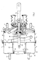
- Figure l is a longitudinal cross section of one form of the servo-booster of the invention, and
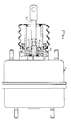
- Figures 2 and 3 are views similar to Figure l illustrating respectively alternative embodiments of the servo-booster of the invention.
- The servo-booster illustrated in Figure l of the drawings has a housing l composed of front and
rear shell portions shell portion 2 includes an annular generallyradial part 2A and an axially extending cylindrical reduceddiameter portion 2B. Surrounding the reduceddiameter shell portion 2B is afurther shell portion 8 which, together with thefront shell portion 2, defines an enclosedreservoir 9 for compressed air. An axially extending part 8A of theshell portion 8 is secured to theshell portions joint 4 between the latter. A radially extendingpart 8B of theshell portion 8 has an in-turned co-axial hollow cylindrical part l0 which lies within the reduceddiameter part 2B of theshell 2 and forms a connection withsaid part 2B. - The interior of the housing l is divided into two chambers A, B by a power piston assembly which includes a piston ll slidable against the internal wall of the
shell portion 3, being sealed thereagainst by a flexible seal l2. The piston assembly also includes a central axially extending hollow hub l3 which extends outwardly through the rear of the casing and receives a force input rod l4 which is connected to a valve piston l5 housed within the hub and supported by a valve member l6 of the hub, the piston l5 and member l6 providing respective seats l5A and l6A for co-operation with a valve member l7 in conventional manner. - The power piston assembly is urged to the right, as seen in the drawing, by a return spring l8 acting between the hub l3 and the
cylindrical part 2B of theshell portion 2. The forward end of the spring l8 is bent to form a radially inwardly projecting retention lug l9 which engages in a hole or slot formed in the in-turned co-axial hollow cylindrical part l0 of theshell portion 8 in order to lock the spring against rotation. The spring is non-rotatably connected at its other end to the hub l3 of the power piston by means of an axially projectingportion 20 of the spring engaged in a suitable aperture of the hub and this enables the spring to resist rotation of the power piston relative to the housing. - An opening 2l through the reservoir is defined by the
cylindrical wall portion 2B and would normally contain a rearwardly extending part of a master cylinder, (not shown) of which a mounting flange would be secured tostuds 22 projecting from the radially extendingpart 8B of theshell portion 8. Anoutput rod 23 of the booster would then be in operative relationship with a piston of the master cylinder. Theshell portion 8 contributes significantly to the overall strength of the booster housing and theshell part 8B provides an advantageous location for attachment of the master cylinder and reaction of the actuation forces arising on the latter. Thereservoir 9 would normally be supplied with compressed air from a suitable source such as a pump mounted on the vehicle and the reservoir is connected by a flexible pipe 24 to aspace 25 within the hub l3, from which it can be fed, when desired, by operation of the valves l5A, l6A to the chambers A and B of the housing l, in conventional manner. The resistance to rotation of the hub referred to above avoids the possibility of the flexible pipe 24 becoming wound around the hub which could result in pinching the pipe. - The attachment of the
shell 8 to theshells cylinder securing studs 22. Thecylindrical part 2B of theshell 2 can thus be seen to perform a function similar to the tie rods found in some conventional master cylinders and minimises the gauge of material required for the various parts of the housing, thereby resulting in a cost effective assembly. Cost effectiveness is further increased by securing theshells shell 2 also acts to resist any tendency for the booster to increase in length, due to deformation of the casing, when high pressure is applied to thereservoir 9, and thus provides a stabilising effect during operation of the reservoir. - Figure 2 illustrates an alternative form of the booster of the invention, in which the piston ll no longer slides against an internal wall of the booster shell, but is sealed to this shell by means of a
deformable diaphragm 30, the ends of which are sealingly secured respectively to the piston ll and the housing l. In this embodiment, the housing proper l consists of front and rear shells 2ʹ and 32 defining the booster chambers A, B and co-operating to trap abead 33 of the seal. Anadditional shell 34 co-operates with radial and axial wall portions 2Aʹ and 2Bʹof the shell 2ʹ to define the reservoir 9ʹ. An axially rearwardly extending portion 3l of theshell 34 provides ashoulder 35 to retain an out-turnedflange 36 of the front shell 2ʹ. It will be seen that the booster housing and reservoir are attached together at a single location, providing a compact and cost effective assembly. The radial wall portion 2Aʹ connects with the axial wall portion 2Bʹ by way of anarcuate part 37 which provides additional strength to the shell 2ʹ and encloses the working length of thediaphragm 30. In all other constructional and operational respects, the booster of Figure 2 is similar to that illustrated in Figure l. - In the embodiment of Figure 3, the housing l and
reservoir 20 are constructed in similar manner to the embodiment of Figure l, except that the control piston l5 carries anabutment key 40 which extends with clearance at either side thereof throughaligned apertures 4l, 42 in the hub l3. Thekey member 40 abuts the housing, as shown, to set a fixed retracted position for the valve piston l5, and the clearance provided at theapertures 4l, 42 enables the piston l5 to move in controlled manner relative to the power piston ll when thering 40 is in abutment with the housing. This enables the valves l5A, l6A to co-operate in a manner such as to control the balance of pressures in the chambers A, B whereby the booster is maintained in a condition of readiness when in its rest position such that substantially instantaneous operation occurs upon actuation of the force input rod l4. - It will be understood that the valve mechanism of the booster of the invention may take any convenient alternative form to that illustrated in the drawings. The reservoir may be of any convenient shape and size other than that illustrated. Although the low pressure existing in one of the booster chambers will normally be atmospheric, low pressure derived from another source is not precluded.
Claims (12)
Applications Claiming Priority (2)
| Application Number | Priority Date | Filing Date | Title |
|---|---|---|---|
| GB8608965 | 1986-04-12 | ||
| GB868608965A GB8608965D0 (en) | 1986-04-12 | 1986-04-12 | Compressed air-operated servo-booster |
Publications (3)
| Publication Number | Publication Date |
|---|---|
| EP0242085A2 true EP0242085A2 (en) | 1987-10-21 |
| EP0242085A3 EP0242085A3 (en) | 1988-01-13 |
| EP0242085B1 EP0242085B1 (en) | 1991-01-23 |
Family
ID=10596112
Family Applications (1)
| Application Number | Title | Priority Date | Filing Date |
|---|---|---|---|
| EP19870302844 Expired EP0242085B1 (en) | 1986-04-12 | 1987-04-01 | Compressed air-operated servo-booster |
Country Status (3)
| Country | Link |
|---|---|
| EP (1) | EP0242085B1 (en) |
| DE (1) | DE3767538D1 (en) |
| GB (1) | GB8608965D0 (en) |
Cited By (3)
| Publication number | Priority date | Publication date | Assignee | Title |
|---|---|---|---|---|
| EP0560739A2 (en) * | 1992-03-06 | 1993-09-15 | F.I.A.C. S.r.l. | A tank pairable to a compressor for aeriform substances |
| EP0644094A1 (en) * | 1993-09-20 | 1995-03-22 | Tokico Ltd. | Pneumatic booster |
| CN1083363C (en) * | 1996-06-14 | 2002-04-24 | 西屋气刹车公司 | Pneumatic pressure operated parking brake for railway vehicle brake system |
Families Citing this family (1)
| Publication number | Priority date | Publication date | Assignee | Title |
|---|---|---|---|---|
| DE4427907B4 (en) * | 1994-08-06 | 2008-04-30 | Continental Teves Ag & Co. Ohg | Pneumatic brake booster for motor vehicles |
Citations (1)
| Publication number | Priority date | Publication date | Assignee | Title |
|---|---|---|---|---|
| DE2453866A1 (en) * | 1973-11-20 | 1975-05-28 | Gen Signal Corp | PNEUMATIC-HYDRAULIC TRANSLATOR |
-
1986
- 1986-04-12 GB GB868608965A patent/GB8608965D0/en active Pending
-
1987
- 1987-04-01 DE DE8787302844T patent/DE3767538D1/en not_active Expired - Lifetime
- 1987-04-01 EP EP19870302844 patent/EP0242085B1/en not_active Expired
Patent Citations (1)
| Publication number | Priority date | Publication date | Assignee | Title |
|---|---|---|---|---|
| DE2453866A1 (en) * | 1973-11-20 | 1975-05-28 | Gen Signal Corp | PNEUMATIC-HYDRAULIC TRANSLATOR |
Cited By (4)
| Publication number | Priority date | Publication date | Assignee | Title |
|---|---|---|---|---|
| EP0560739A2 (en) * | 1992-03-06 | 1993-09-15 | F.I.A.C. S.r.l. | A tank pairable to a compressor for aeriform substances |
| EP0560739A3 (en) * | 1992-03-06 | 1995-01-25 | Fiac Srl | A tank pairable to a compressor for aeriform substances |
| EP0644094A1 (en) * | 1993-09-20 | 1995-03-22 | Tokico Ltd. | Pneumatic booster |
| CN1083363C (en) * | 1996-06-14 | 2002-04-24 | 西屋气刹车公司 | Pneumatic pressure operated parking brake for railway vehicle brake system |
Also Published As
| Publication number | Publication date |
|---|---|
| EP0242085A3 (en) | 1988-01-13 |
| EP0242085B1 (en) | 1991-01-23 |
| GB8608965D0 (en) | 1986-05-14 |
| DE3767538D1 (en) | 1991-02-28 |
Similar Documents
| Publication | Publication Date | Title |
|---|---|---|
| US5699713A (en) | Brake booster | |
| US4417500A (en) | Air pressure servomotor | |
| US4450688A (en) | Brake booster for automotive vehicles | |
| US3312147A (en) | Fluid pressure servomotor | |
| US3517588A (en) | Servomotor and valve means | |
| KR0134616B1 (en) | Servo brake booster | |
| US4469009A (en) | Pneumatic booster | |
| US4394833A (en) | Brake booster | |
| US4487022A (en) | Brake actuator | |
| US6189437B1 (en) | Brake booster having means for mounting on a wall | |
| US3613506A (en) | Servomotor having improved no-power operation | |
| US4328738A (en) | Vacuum servo booster | |
| US4813338A (en) | Pneumatically operated servo-booster | |
| EP0242085B1 (en) | Compressed air-operated servo-booster | |
| US4794844A (en) | Pneumatically operated servo-booster | |
| US4416191A (en) | Vacuum booster device | |
| KR880002072B1 (en) | Servomotor with power assistance | |
| US4393750A (en) | Brake booster | |
| KR100311983B1 (en) | Pneumatic Actuated Booster for Vehicle Braking System | |
| CZ210695A3 (en) | Vacuum brake booster for motor vehicles | |
| US4407184A (en) | Pneumatic servo booster | |
| US5074191A (en) | Brake booster housing with a hub structure containing a valve mechanism arranged inside the housing | |
| KR970010067B1 (en) | Hydraulic brake system, and brake booster and control valve | |
| JPH11503684A (en) | Pneumatic brake booster | |
| JPH0360708B2 (en) |
Legal Events
| Date | Code | Title | Description |
|---|---|---|---|
| PUAI | Public reference made under article 153(3) epc to a published international application that has entered the european phase |
Free format text: ORIGINAL CODE: 0009012 |
|
| AK | Designated contracting states |
Kind code of ref document: A2 Designated state(s): DE FR GB IT |
|
| PUAL | Search report despatched |
Free format text: ORIGINAL CODE: 0009013 |
|
| AK | Designated contracting states |
Kind code of ref document: A3 Designated state(s): DE FR GB IT |
|
| 17P | Request for examination filed |
Effective date: 19880701 |
|
| 17Q | First examination report despatched |
Effective date: 19890802 |
|
| GRAA | (expected) grant |
Free format text: ORIGINAL CODE: 0009210 |
|
| AK | Designated contracting states |
Kind code of ref document: B1 Designated state(s): DE FR GB IT |
|
| ITF | It: translation for a ep patent filed | ||
| REF | Corresponds to: |
Ref document number: 3767538 Country of ref document: DE Date of ref document: 19910228 |
|
| ET | Fr: translation filed | ||
| PLBE | No opposition filed within time limit |
Free format text: ORIGINAL CODE: 0009261 |
|
| STAA | Information on the status of an ep patent application or granted ep patent |
Free format text: STATUS: NO OPPOSITION FILED WITHIN TIME LIMIT |
|
| 26N | No opposition filed | ||
| PGFP | Annual fee paid to national office [announced via postgrant information from national office to epo] |
Ref country code: GB Payment date: 19980323 Year of fee payment: 12 |
|
| PGFP | Annual fee paid to national office [announced via postgrant information from national office to epo] |
Ref country code: FR Payment date: 19980409 Year of fee payment: 12 |
|
| PGFP | Annual fee paid to national office [announced via postgrant information from national office to epo] |
Ref country code: DE Payment date: 19980414 Year of fee payment: 12 |
|
| PG25 | Lapsed in a contracting state [announced via postgrant information from national office to epo] |
Ref country code: GB Free format text: LAPSE BECAUSE OF NON-PAYMENT OF DUE FEES Effective date: 19990401 |
|
| GBPC | Gb: european patent ceased through non-payment of renewal fee |
Effective date: 19990401 |
|
| PG25 | Lapsed in a contracting state [announced via postgrant information from national office to epo] |
Ref country code: FR Free format text: LAPSE BECAUSE OF NON-PAYMENT OF DUE FEES Effective date: 19991231 |
|
| REG | Reference to a national code |
Ref country code: FR Ref legal event code: ST |
|
| PG25 | Lapsed in a contracting state [announced via postgrant information from national office to epo] |
Ref country code: DE Free format text: LAPSE BECAUSE OF NON-PAYMENT OF DUE FEES Effective date: 20000201 |
|
| PG25 | Lapsed in a contracting state [announced via postgrant information from national office to epo] |
Ref country code: IT Free format text: LAPSE BECAUSE OF NON-PAYMENT OF DUE FEES;WARNING: LAPSES OF ITALIAN PATENTS WITH EFFECTIVE DATE BEFORE 2007 MAY HAVE OCCURRED AT ANY TIME BEFORE 2007. THE CORRECT EFFECTIVE DATE MAY BE DIFFERENT FROM THE ONE RECORDED. Effective date: 20050401 |