EP0242017B1 - Article grouping technique and apparatus - Google Patents
Article grouping technique and apparatus Download PDFInfo
- Publication number
- EP0242017B1 EP0242017B1 EP87300419A EP87300419A EP0242017B1 EP 0242017 B1 EP0242017 B1 EP 0242017B1 EP 87300419 A EP87300419 A EP 87300419A EP 87300419 A EP87300419 A EP 87300419A EP 0242017 B1 EP0242017 B1 EP 0242017B1
- Authority
- EP
- European Patent Office
- Prior art keywords
- articles
- group
- groups
- open ends
- cartons
- Prior art date
- Legal status (The legal status is an assumption and is not a legal conclusion. Google has not performed a legal analysis and makes no representation as to the accuracy of the status listed.)
- Expired
Links
- 238000000034 method Methods 0.000 title claims description 12
- 230000000712 assembly Effects 0.000 description 7
- 238000000429 assembly Methods 0.000 description 7
- 238000004806 packaging method and process Methods 0.000 description 5
- 230000002093 peripheral effect Effects 0.000 description 3
- 239000011800 void material Substances 0.000 description 3
- 230000001154 acute effect Effects 0.000 description 2
- 238000006073 displacement reaction Methods 0.000 description 1
- 230000000694 effects Effects 0.000 description 1
- 239000000463 material Substances 0.000 description 1
- 229920003023 plastic Polymers 0.000 description 1
- 239000004033 plastic Substances 0.000 description 1
- 238000011144 upstream manufacturing Methods 0.000 description 1
Images


Classifications
-
- B—PERFORMING OPERATIONS; TRANSPORTING
- B65—CONVEYING; PACKING; STORING; HANDLING THIN OR FILAMENTARY MATERIAL
- B65G—TRANSPORT OR STORAGE DEVICES, e.g. CONVEYORS FOR LOADING OR TIPPING, SHOP CONVEYOR SYSTEMS OR PNEUMATIC TUBE CONVEYORS
- B65G47/00—Article or material-handling devices associated with conveyors; Methods employing such devices
- B65G47/74—Feeding, transfer, or discharging devices of particular kinds or types
- B65G47/84—Star-shaped wheels or devices having endless travelling belts or chains, the wheels or devices being equipped with article-engaging elements
- B65G47/841—Devices having endless travelling belts or chains equipped with article-engaging elements
- B65G47/845—Devices having endless travelling belts or chains equipped with article-engaging elements the article engaging elements being pushers moving in parallel and independently from the supporting conveyor
-
- B—PERFORMING OPERATIONS; TRANSPORTING
- B65—CONVEYING; PACKING; STORING; HANDLING THIN OR FILAMENTARY MATERIAL
- B65B—MACHINES, APPARATUS OR DEVICES FOR, OR METHODS OF, PACKAGING ARTICLES OR MATERIALS; UNPACKING
- B65B21/00—Packaging or unpacking of bottles
- B65B21/24—Enclosing bottles in wrappers
- B65B21/242—Enclosing bottles in wrappers in collapsed carton sleeves
-
- B—PERFORMING OPERATIONS; TRANSPORTING
- B65—CONVEYING; PACKING; STORING; HANDLING THIN OR FILAMENTARY MATERIAL
- B65B—MACHINES, APPARATUS OR DEVICES FOR, OR METHODS OF, PACKAGING ARTICLES OR MATERIALS; UNPACKING
- B65B35/00—Supplying, feeding, arranging or orientating articles to be packaged
- B65B35/30—Arranging and feeding articles in groups
- B65B35/54—Feeding articles along multiple paths to a single packaging position
Definitions
- This invention relates to an article grouping technique in which groups of cylindrical articles such as bottles or cans are loaded into open-ended sleeves and to a machine for continuously loading groups of such articles so that one consolidated group of articles is formed within each sleeve.
- Patents US-A-4,098,050 and US-A-2,535,880 disclose packaging techniques in which the packaged containers are arranged in a nested (staggered) row configuration i.e. in which each container in one row is disposed between a pair of neighbouring containers in each of the next adjacent rows. In some arrangements according to the present invention, this configuration is achieved by a method and means which allow continuous flow grouping of the containers which is not a technique described in these prior publications.
- one aspect of the present invention provides a method of continuously loading groups of cylindrical articles such as bottles or cans into open-ended sleeves (C) comprising the steps of conveying the open-ended sleeves along a feed path with their open ends presented at opposite sides of the feed path, feeding streams of articles along the opposing open ends of said sleeves, forming opposing groups of articles of which each comprises at least three adjacent rows of articles disposed in general alignment with said open ends of said sleeve characterized by reorganising said groups so that at least one article in one group projects in the direction of the adjacent open end of the sleeve and with respect to the adjacent articles of said one group and at least one corresponding matching recess is formed in the opposing group, moving said opposing groups toward each other and into the open ends of said sleeve so that one consolidated group of articles is formed within the sleeve whereby said projecting articles of said one group occupies said recess in said other group.
- European Patent No 0 017 333 discloses a packaging machine as specified in the first part of claim 5, which includes a fixed horizontal base plate over which a plurality of spaced apart metering bars are movable with open ended sleeve type containers disposed therebetween.
- Fixed guides are disposed on each side of the machine and are convergent in the direction of sleeve feed so that primary packages e.g. bottles supplied to the fixed putter on each side of the machine by infeed conveyors are forced by line pressure into the path of movement of the end portions of the metering bars.
- the metering bars effect a metering operation whereby a predetermined number of primary packages are entrapped between spaced adjacent metering bars at both ends thereof so that continued movement of the metering bars relative to the fixed guides forces the group of articles into each end of the open ended sleeve.
- the sleeves are loaded so that several uniform rows of articles are present within the sleeve at the completion of loading whereafter the ends of the sleeve are closed.
- this further aspect of the present invention is concerned with a packaging machine which not only can group and end load articles into the ends of an open-ended sleeve but is adapted to conduct the loading so that the articles are guided into the open ends of the sleeves, and the articles are rearranged.
- another aspect of the invention provides a machine for continuously loading groups of cylindrical articles such as bottles or cans into sleeve-type cartons through the open ends thereof
- machine comprises support means extending longitudinally of the machine, a series of transversely extending metering bars mounted on endless chains for movement in the machine direction above said support means and arranged in spaced relationship to receive said cartons therebetween with the open ends of the cartons being disposed on opposite sides of said support means, infeed means extending on each side of said support means for feeding said articles in a continuous stream, guide means disposed above said infeed means and converging toward the open ends of said cartons, said metering bars having shaped end portions effective to intersect the path of said articles advancing on said infeed means to separate said stream of articles into groups of which each comprises at least three adjacent rows of articles so that a predetermined number of articles is confined between adjacent metering bars on each side of said support means and means for pushing said groups of articles transversely into the open ends of said cartons, characterised in that each metering bar is
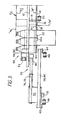
- FIGURE 1 is a general schematic plan view of a packaging machine showing at successive locations bottle groups being loaded into open-ended cartons
- FIGURE 2 is a schematic vertical cross-sectional view of the left-hand side of the machine about the central axis of the machine as viewed at the position of carton C2 in Figure 1
- FIGURES 3 and 4 are views similar to Figure 2 but as viewed at the positions of cartons C3 and C4 in Figure 1.
- a fixed base plate is designated by reference numeral 10 and is supported centrally of the machine frame by a structure not shown in the drawings.
- a plurality of spaced apart movable metering bars 12 are supported in spaced relationship above the base plate by support posts 14, which extend through slots 16 formed in the base plate.
- the open end sleeve type cartons C1-C4 are withdrawn from a hopper (not shown) and deposited between successive metering bars 12 by known feeder means so that the cartons then occupy the positions shown between the horizontally disposed spaced apart metering bars.
- a stack of collapsed open-ended sleeve cartons initially are disposed in a hopper above the infeed end of the machine and the cartons are erected from their collapsed condition into their tubular configuration during withdrawal from the hopper.
- each support post 14 is carried by a bracket 18 connected to an endless chain 20 for imparting movement to the metering bars 12 from left to right as viewed in Figure 1.
- the endless chain 20 is mounted in known manner on sprockets and is driven so that the upper working reach of the endless chain moves from left to right as viewed in Figure 1 so as to move the metering bars from left to right.
- the cartons interposed between the metering bars are slidably supported by the fixed base plate 10 which preferably is formed of low friction plastics material. It will be appreciated that each metering bar also has a further support post connected to another endless chain on the opposite side of the central vertical axis X-X of the machine.
- each infeed convey may comprise two like conveyors separated about the mid-point 22a ( Figure 3).
- the upstream portions of infeed conveyors are divergent towards the carton flow path, that is they extend at an acute angle with respect to the carton feed path.
- Bottles in rows R1 and R2 are fed along conveyor 22, the rows being separated by fixed guide bars 26, 28 and 30.
- bottles in rows R3 and R4 are fed along conveyor 24, the rows being separated by fixed guide bars 32, 34 and 36.
- these bars serve as metering devices for entrapping a predetermined number of bottles between successive bars due to the fact that the conveyors 22, 24 and their guides 26, 28, 30 and 32, 34, 36 are directed at an acute angle inwardly toward the path of movement of the metering bars.
- the metering bars entrap a group of twelve bottles on each of the conveyors 22 and 24 arranged in two parallel rows R1, R2 and R3, R4 having six bottles per row.
- the conveyors and their associated guides extend parallel to the carton flow path so that the bottle groups are conveyed alongside the opposed open ends of the carton sleeves.
- an additional infeed conveyor 38 is provided alongside the infeed conveyor 22 having bottle row R1 and the bottles in a further bottle row R5 conveyed therealong are guided by fixed guides 30 and 40. At or about the position of bottle grouping by the metering bars 12, the additional conveyor is deflected outwardly so that it extends parallel to the carton feed path but spaced away from infeed conveyor 22.
- a bottle flow control device is provided at the outfeed end of the additional conveyor 38 and comprises a metering disc 42 disposed adjacent the initial portion of conveyor 22 which extends parallel to the flow path. Additional conveyor 38 is flanked by fixed guides 40 and 30a.
- the metering disc 42 is mounted for rotation, by suitable drive means, in a horizontal plane between a fixed elongate platform 44 and below the metering disc and an endless series of bottle conveying elements designated generally by the reference numeral 46 located above the disc.
- Platform 44 has an initial arcuate portion flanked by a curved portion 30b of the fixed guide 30a and a linear portion extending alongside the conveyor 22 in the flow direction 'F'.
- the curved portion 30b of the fixed guide merges with the linear fixed guide 30 where guide 30 extends parallel to the flow direction 'F'.
- Platform 44 is disposed in the same plane as conveyors 22, 24 and the base plate 10 of the machine.
- the endless series of bottle conveying elements comprises a number of pairs of spaced conveyor blocks 48, 50 spaced apart a predetermined distance along an endless chain 52 entrained about spaced sprockets.
- Each pair of conveyor blocks extends outwardly from and have a working face which is shaped to form between the blocks a bottle receiving cavity 54.
- the conveyor blocks are constrained to move along a working reach parallel to and adjacent bottle row R1 in the feed direction F and along a parallel return reach remote from bottle row R1 opposed to the feed direction F. As the conveyor blocks transfer from the return reach to the working reach the open mouth of each bottle receiving cavity passes closely adjacent the outfeed end of the additional infeed conveyor 38.
- Metering disc 42 is positioned such that during rotation thereof the major portion of its periphery covering an arc of about 270° passes across the outfeed end of conveyor 38 so that no bottles are permitted to issue therefrom. However, a peripheral recessed portion 42b of the disc covering an arc of about 90° is formed in the disc which progressively allows the leading bottle BX to issue from conveyor 38 as the recessed portion 42b passes across the outfeed end of the conveyor 38.
- the disposition of the conveyor blocks along endless chain 52 and the rotation speeds of the metering disc and drive sprocket of chain 52 is such that a bottle receiving cavity is present at the outfeed end of conveyor when the peripheral recessed portion 42b of the disc is at the location shown.
- the mouth of a bottle receiving cavity 54 is positioned to receive the lead bottle. Thereafter, as the lead bottle progressively engages the more severely reduced diametral extent of the recessed peripheral portion, the lead bottle correspondingly is further received into the cavity until when fully received into the cavity engages approximately an 180° arc of the bottle circumference.
- the next succeeding bottle on conveyor 38 is likewise received by the next succeeding pair of bottle conveying blocks.
- the working reach of the endless chain is positioned so that the conveying blocks receive portions of the bottle extending above the metering bars as seen in Figure 3.
- the conveying blocks also are located along the endless chain 52 so that two extra bottles BX1 and BX2 are introduced to each group of bottles conveyed in the feed direction 'F' on conveyor 22.
- bottle BX1 is held and moved by conveyor blocks 48, 50 such that it is located alongside the second pair of bottles B2a, B2b in the group and that bottle BX2 is held and moved by the next succeeding conveyor blocks such that it is located alongside the penultimate pair of bottles B5a, B5b in the same group.
- Endless chain 52 is moved in synchronism with conveyor 22 so that bottles BX1 and BX2 are maintained in these relative positions.
- an end loading mechanism 56, 56a is provided at each side of the machine outboard of the ends of the metering bars between the positions of cartons C2- C4 and is described below.
- End loading mechanism 56 comprises a pair of lower fixed parallel shafts 58, 60 connected as at each of their opposite ends by mounting elements 62, 64 to endless chains 66, 68 respectively.
- Endless chains 66, 68 are entrained about spaced sprockets (not shown) so that the chains are driven in their working reach in the flow direction 'F'.
- a slidable cam follower block 70 has its lower end mounted on shafts 66, 68 for axial movement therealong and a cam roller 72 projected downwardly from the lower face of the cam follower block 70 and engages in a fixed cam track 74.
- the cam follower block is connected to one end of a pair of parallel rods 76, 78 the opposite end of which carry a bottle pusher element or plunger 80.
- the bottle pusher element 80 has a front face formed to provide a bottle receiving recess 82 but for other configurations of article grouping the front face may be formed to provide a projection.
- the whole end loading mechanism 56 moves alongside a bottle group in the flow direction and a series of pairs of such cam follower block assemblies including parallel shafts and bottle pusher elements are mounted in side by side relationship along the chains 66, 68.
- the arrangement is such that a pair of these pusher assemblies is provided on each side of the carton and bottle flow path for each group of bottles.
- the pusher assemblies are positioned so that when the pusher elements come alongside a bottle group at carton position C2, pusher element 80 has its recess 82 aligned with bottle pair B5c, B5d; pusher element 80 ⁇ has its recess aligned with bottle pair B2c, B2d; pusher element 80a has its recess 82a aligned with bottle pair B5a, B5b and pusher element 80a ⁇ has its recess 82a ⁇ aligned with bottle pair B2a, B2b.
- cam track 74 associated with roller follower 72 extends at an oblique angle inwardly of the flow path 'F' of the machine between carton locations C2 and C4 the track being at its minimum distance from the support plate 10 at carton position C4. At carton position C4 the cam track extends away from the machine at an oblique angle.
- the arrangement of cam follower block 70 ⁇ and cam track 74 ⁇ is similar, these assemblies and their associated cam tracks being vertically displaced relative to one another. On the opposite side of the machine, a like arrangement of pusher assemblies and cam tracks is provided.
- each of the metering bars has a forwardly extending ramp surface 12b, 12b ⁇ along its leading edge and a rearwardly extending ramp surface 12c, 12c ⁇ along its trailing edge adjacent the ends of the metering bars.
- a pair of successive metering bars provide a central waisted zone occupied by the tubular carton sleeve into which the bottle groups are guided during end loading.
- bottle B5d id engaged in the pusher recess 82 and bottle pairs B6c, B6d and B4c B4d are displaced inwardly relative to bottle pair B5c, B5d, thus creating a void V1 in front of bottle B5c.
- bottle B2d is engaged in the pusher recess 82 ⁇ and bottle pairs B3c, B3d and B1c, B1d are displaced inwardly relative to bottle pair B2c, B2d thus creating a void V2 in front of bottle B2c.
- This displacing action is created by virtue of the restrictive passageway formed by the juxtaposed ramp surfaces 12b, 12c of the adjacent metering bars which are engaged by the leading and trailing bottle pair during transverse movement of the bottle pushers assemblies and also by virtue of the shaped front face of the pusher assembly.
- the pusher elements progressively are retracted from the carton sleeve ends caused by movement the roller followers of the cam blocks being guided along the outwardly extending portions of their cam tracks.
- Base panel 'p' is superposed on support plate 10 and bottom end closure panels 'q' hinged thereto extend downwardly through the slot 16 in support plate 10.
- Top panel 'p1' and top end closure panels 'q1' hinged thereto are aligned in spaced parallel relationship with respect to the plane of the support plate 10 thus giving an unobstructed end aperture through which the bottles may be transferred from the side conveyors of the machine.
Landscapes
- Engineering & Computer Science (AREA)
- Mechanical Engineering (AREA)
- Wrapping Of Specific Fragile Articles (AREA)
Description
- This invention relates to an article grouping technique in which groups of cylindrical articles such as bottles or cans are loaded into open-ended sleeves and to a machine for continuously loading groups of such articles so that one consolidated group of articles is formed within each sleeve.
- Patents US-A-4,098,050 and US-A-2,535,880 disclose packaging techniques in which the packaged containers are arranged in a nested (staggered) row configuration i.e. in which each container in one row is disposed between a pair of neighbouring containers in each of the next adjacent rows. In some arrangements according to the present invention, this configuration is achieved by a method and means which allow continuous flow grouping of the containers which is not a technique described in these prior publications.
- Thus one aspect of the present invention provides a method of continuously loading groups of cylindrical articles such as bottles or cans into open-ended sleeves (C) comprising the steps of conveying the open-ended sleeves along a feed path with their open ends presented at opposite sides of the feed path, feeding streams of articles along the opposing open ends of said sleeves, forming opposing groups of articles of which each comprises at least three adjacent rows of articles disposed in general alignment with said open ends of said sleeve characterized by reorganising said groups so that at least one article in one group projects in the direction of the adjacent open end of the sleeve and with respect to the adjacent articles of said one group and at least one corresponding matching recess is formed in the opposing group, moving said opposing groups toward each other and into the open ends of said sleeve so that one consolidated group of articles is formed within the sleeve whereby said projecting articles of said one group occupies said recess in said other group. European Patent No 0 017 333 discloses a packaging machine as specified in the first part of claim 5, which includes a fixed horizontal base plate over which a plurality of spaced apart metering bars are movable with open ended sleeve type containers disposed therebetween. Fixed guides are disposed on each side of the machine and are convergent in the direction of sleeve feed so that primary packages e.g. bottles supplied to the fixed putter on each side of the machine by infeed conveyors are forced by line pressure into the path of movement of the end portions of the metering bars. The metering bars effect a metering operation whereby a predetermined number of primary packages are entrapped between spaced adjacent metering bars at both ends thereof so that continued movement of the metering bars relative to the fixed guides forces the group of articles into each end of the open ended sleeve.
- In the above arrangement, the sleeves are loaded so that several uniform rows of articles are present within the sleeve at the completion of loading whereafter the ends of the sleeve are closed.
- By contrast, this further aspect of the present invention is concerned with a packaging machine which not only can group and end load articles into the ends of an open-ended sleeve but is adapted to conduct the loading so that the articles are guided into the open ends of the sleeves, and the articles are rearranged.
- Thus, another aspect of the invention provides a machine for continuously loading groups of cylindrical articles such as bottles or cans into sleeve-type cartons through the open ends thereof which machine comprises support means extending longitudinally of the machine, a series of transversely extending metering bars mounted on endless chains for movement in the machine direction above said support means and arranged in spaced relationship to receive said cartons therebetween with the open ends of the cartons being disposed on opposite sides of said support means, infeed means extending on each side of said support means for feeding said articles in a continuous stream, guide means disposed above said infeed means and converging toward the open ends of said cartons, said metering bars having shaped end portions effective to intersect the path of said articles advancing on said infeed means to separate said stream of articles into groups of which each comprises at least three adjacent rows of articles so that a predetermined number of articles is confined between adjacent metering bars on each side of said support means and means for pushing said groups of articles transversely into the open ends of said cartons, characterised in that each metering bar is provided with ramp surfaces projecting forwardly and rearwardly from the leading and trailing edges thereof respectively and extending intermediate said shaped end portions whereby a central reduced space is formed between successive metering bars at the location where said carton is received, said ramp surfaces being arranged and configured so as to guide said articles into the open ends of said cartons and in that said pushing means are effective to rearrange said articles in said groups as the articles are pushed along said ramp surfaces toward the open ends of said cartons, so that at least one article in said one group of articles projects with respect to the adjacent articles of said one group and a matching recess is formed in the opposite group on the other side of said support means.
- A method and machine embodying the invention will now be described by way of example with reference to the accompanying drawings, in which:-
FIGURE 1 is a general schematic plan view of a packaging machine showing at successive locations bottle groups being loaded into open-ended cartons;
FIGURE 2 is a schematic vertical cross-sectional view of the left-hand side of the machine about the central axis of the machine as viewed at the position of carton C² in Figure 1; and
FIGURES 3 and 4 are views similar to Figure 2 but as viewed at the positions of cartons C3 and C4 in Figure 1. - With reference to the drawings, a fixed base plate is designated by
reference numeral 10 and is supported centrally of the machine frame by a structure not shown in the drawings. A plurality of spaced apartmovable metering bars 12 are supported in spaced relationship above the base plate bysupport posts 14, which extend throughslots 16 formed in the base plate. - The open end sleeve type cartons C1-C4 are withdrawn from a hopper (not shown) and deposited between
successive metering bars 12 by known feeder means so that the cartons then occupy the positions shown between the horizontally disposed spaced apart metering bars. As is conventional practice, a stack of collapsed open-ended sleeve cartons initially are disposed in a hopper above the infeed end of the machine and the cartons are erected from their collapsed condition into their tubular configuration during withdrawal from the hopper. - The lower end of each
support post 14 is carried by abracket 18 connected to anendless chain 20 for imparting movement to themetering bars 12 from left to right as viewed in Figure 1. Theendless chain 20 is mounted in known manner on sprockets and is driven so that the upper working reach of the endless chain moves from left to right as viewed in Figure 1 so as to move the metering bars from left to right. The cartons interposed between the metering bars are slidably supported by thefixed base plate 10 which preferably is formed of low friction plastics material. It will be appreciated that each metering bar also has a further support post connected to another endless chain on the opposite side of the central vertical axis X-X of the machine. - Primary packages e.g. bottles to be loaded into each of the cartons are supplied to the machine on infeed
conveyors base plate 12. In practice, it may be desirable to construct each infeed convey as a plurality of separate conveyors since the incoming bottles are arranged in two rows,e.g. conveyor 22 may comprise two like conveyors separated about themid-point 22a (Figure 3). The upstream portions of infeed conveyors are divergent towards the carton flow path, that is they extend at an acute angle with respect to the carton feed path. - Bottles in rows R₁ and R₂ are fed along
conveyor 22, the rows being separated byfixed guide bars conveyor 24, the rows being separated byfixed guide bars - As is known in the art, since the length of the
metering bars 12 is fixed and since the end portions of these bars have a backwardly raked trailing edge to form a wedge-shaped end at 12a, these bars serve as metering devices for entrapping a predetermined number of bottles between successive bars due to the fact that theconveyors guides - In this embodiment the metering bars entrap a group of twelve bottles on each of the
conveyors - As will become apparent, in order to form the bottles into the required configuration, it is necessary to introduce two extra bottles into one of the bottle groups. In order to achieve this, an additional infeed
conveyor 38 is provided alongside the infeedconveyor 22 having bottle row R₁ and the bottles in a further bottle row R₅ conveyed therealong are guided byfixed guides metering bars 12, the additional conveyor is deflected outwardly so that it extends parallel to the carton feed path but spaced away from infeedconveyor 22. A bottle flow control device is provided at the outfeed end of theadditional conveyor 38 and comprises ametering disc 42 disposed adjacent the initial portion ofconveyor 22 which extends parallel to the flow path.Additional conveyor 38 is flanked byfixed guides - The
metering disc 42 is mounted for rotation, by suitable drive means, in a horizontal plane between a fixedelongate platform 44 and below the metering disc and an endless series of bottle conveying elements designated generally by thereference numeral 46 located above the disc.Platform 44 has an initial arcuate portion flanked by acurved portion 30b of thefixed guide 30a and a linear portion extending alongside theconveyor 22 in the flow direction 'F'. Thecurved portion 30b of the fixed guide merges with the linearfixed guide 30 whereguide 30 extends parallel to the flow direction 'F'.Platform 44 is disposed in the same plane asconveyors base plate 10 of the machine. - The endless series of bottle conveying elements comprises a number of pairs of spaced
conveyor blocks endless chain 52 entrained about spaced sprockets. - Each pair of conveyor blocks extends outwardly from and have a working face which is shaped to form between the blocks a
bottle receiving cavity 54. The conveyor blocks are constrained to move along a working reach parallel to and adjacent bottle row R₁ in the feed direction F and along a parallel return reach remote from bottle row R₁ opposed to the feed direction F. As the conveyor blocks transfer from the return reach to the working reach the open mouth of each bottle receiving cavity passes closely adjacent the outfeed end of the additional infeedconveyor 38. -
Metering disc 42 is positioned such that during rotation thereof the major portion of its periphery covering an arc of about 270° passes across the outfeed end ofconveyor 38 so that no bottles are permitted to issue therefrom. However, a peripheral recessedportion 42b of the disc covering an arc of about 90° is formed in the disc which progressively allows the leading bottle BX to issue fromconveyor 38 as therecessed portion 42b passes across the outfeed end of theconveyor 38. The disposition of the conveyor blocks alongendless chain 52 and the rotation speeds of the metering disc and drive sprocket ofchain 52 is such that a bottle receiving cavity is present at the outfeed end of conveyor when the peripheral recessedportion 42b of the disc is at the location shown. It is at this location whereat the lead bottle engages about midway along the recessed periphery that the mouth of abottle receiving cavity 54 is positioned to receive the lead bottle. Thereafter, as the lead bottle progressively engages the more severely reduced diametral extent of the recessed peripheral portion, the lead bottle correspondingly is further received into the cavity until when fully received into the cavity engages approximately an 180° arc of the bottle circumference. - The next succeeding bottle on
conveyor 38 is likewise received by the next succeeding pair of bottle conveying blocks. The working reach of the endless chain is positioned so that the conveying blocks receive portions of the bottle extending above the metering bars as seen in Figure 3. The conveying blocks also are located along theendless chain 52 so that two extra bottles BX1 and BX2 are introduced to each group of bottles conveyed in the feed direction 'F' onconveyor 22. It will be seen that bottle BX1 is held and moved byconveyor blocks Endless chain 52 is moved in synchronism withconveyor 22 so that bottles BX1 and BX2 are maintained in these relative positions. - The bottle subgroups conveyed on either side of the base plate are now ready to be end loaded into a carton. For this purpose, an
end loading mechanism 56, 56a is provided at each side of the machine outboard of the ends of the metering bars between the positions of cartons C₂- C₄ and is described below. -
End loading mechanism 56 comprises a pair of lower fixedparallel shafts mounting elements endless chains Endless chains cam follower block 70 has its lower end mounted onshafts cam roller 72 projected downwardly from the lower face of thecam follower block 70 and engages in afixed cam track 74. At its upper end the cam follower block is connected to one end of a pair ofparallel rods bottle pusher element 80 has a front face formed to provide abottle receiving recess 82 but for other configurations of article grouping the front face may be formed to provide a projection. - The whole
end loading mechanism 56 moves alongside a bottle group in the flow direction and a series of pairs of such cam follower block assemblies including parallel shafts and bottle pusher elements are mounted in side by side relationship along thechains pusher element 80 has itsrecess 82 aligned with bottle pair B5c, B5d; pusher element 80ʹ has its recess aligned with bottle pair B2c, B2d;pusher element 80a has itsrecess 82a aligned with bottle pair B5a, B5b and pusher element 80aʹ has its recess 82aʹ aligned with bottle pair B2a, B2b. - Referring to
cam follower block 70, thecam track 74 associated withroller follower 72 extends at an oblique angle inwardly of the flow path 'F' of the machine between carton locations C2 and C4 the track being at its minimum distance from thesupport plate 10 at carton position C4. At carton position C4 the cam track extends away from the machine at an oblique angle. The arrangement of cam follower block 70ʹ and cam track 74ʹ is similar, these assemblies and their associated cam tracks being vertically displaced relative to one another. On the opposite side of the machine, a like arrangement of pusher assemblies and cam tracks is provided. - Thus as the pusher assemblies are moved forwardly in the flow direction, the cam blocks and therefor the pusher elements simultaneously are moved progressively in a transverse direction by virtue of the guidance given by the cam tracks. At carton position C3
bottle pusher elements bottle pusher element 80a and 80aʹ has engaged the bottle group on the opposite side of the machine. - It will be seen that each of the metering bars has a forwardly extending
ramp surface 12b, 12bʹ along its leading edge and a rearwardly extendingramp surface 12c, 12cʹ along its trailing edge adjacent the ends of the metering bars. Thus, a pair of successive metering bars provide a central waisted zone occupied by the tubular carton sleeve into which the bottle groups are guided during end loading. At carton position C3, bottle B5d id engaged in thepusher recess 82 and bottle pairs B6c, B6d and B4c B4d are displaced inwardly relative to bottle pair B5c, B5d, thus creating a void V1 in front of bottle B5c. Likewise, bottle B2d is engaged in the pusher recess 82ʹ and bottle pairs B3c, B3d and B1c, B1d are displaced inwardly relative to bottle pair B2c, B2d thus creating a void V2 in front of bottle B2c. - This displacing action is created by virtue of the restrictive passageway formed by the juxtaposed ramp surfaces 12b, 12c of the adjacent metering bars which are engaged by the leading and trailing bottle pair during transverse movement of the bottle pushers assemblies and also by virtue of the shaped front face of the pusher assembly.
- On the opposite side of the machine, at carton position C3, a similar displacement of the bottle group occurs except that by virtue of the presence of extra bottles BX1 and BX2 in alignment with bottle pairs B2a, B2b and B5a, B5b, the bottles B2b and B5b are pushed proud of the other bottles in the group.
- At carton position C4 the pusher elements have arrived at their furthest inward extension so that the opposed bottle groups are pushed towards one another into the carton sleeve occupying the waisted zone between the adjacent metering bars. When fully loaded bottle B5b nests into the void V1 thus creating end voids at the ends of the combined bottle group between bottle rows B2 and B5.
- The pusher elements progressively are retracted from the carton sleeve ends caused by movement the roller followers of the cam blocks being guided along the outwardly extending portions of their cam tracks.
- Thereafter, the carton sleeve ends may be closed to complete the packaging operation.
- Referring to Figure 3, the relative position of the carton end panels to permit end loading is shown schematically. Base panel 'p' is superposed on
support plate 10 and bottom end closure panels 'q' hinged thereto extend downwardly through theslot 16 insupport plate 10. Top panel 'p1' and top end closure panels 'q1' hinged thereto are aligned in spaced parallel relationship with respect to the plane of thesupport plate 10 thus giving an unobstructed end aperture through which the bottles may be transferred from the side conveyors of the machine. - It is envisaged that other nested (staggered) row arrangements of articles can be produced by the method and apparatus according to this invention e.g. a hexagonal configuration produced from sub-groups of half the number of bottles than those described in the specific embodiment and utilising only one pusher assembly for each sub-group.
Claims (8)
- A method of continuously loading groups of cylindrical articles such as bottles or cans into open-ended sleeves (C), comprising the steps of conveying the open-ended sleeves along a feed path with their open ends presented at opposite sides of the feed path, feeding streams of articles along the opposing open ends of said sleeves, forming opposing groups of articles of which each comprises at least three adjacent rows of articles disposed in general alignment with said open ends of said sleeve characterized by reorganising said groups so that at least one article in one group projects in the direction of the adjacent open end of the sleeve and with respect to the adjacent articles of said one group and at least one corresponding matching recess is formed in the opposing group, moving said opposing groups toward each other and into the open ends of said sleeve so that one consolidated group of articles is formed within the sleeve whereby said projecting articles of said one group occupies said recess in said other group.
- The method according to claim 1, further characterised in that articles in said groups are arranged in mutually nesting relationship when being moved into said sleeve.
- The method according to claim 1 or claim 2, wherein the number of articles in said one group exceeds the number of articles in said opposing group by at least one.
- The method according to any of the preceding claims wherein each of said groups are reorganised so as to provide an intermediate recess at the ends of said sleeve when positioned therein.
- A machine for continuously loading groups of cylindrical articles such as bottles or cans into sleeve-type cartons (c) through the open ends thereof which machine comprises support means (10) extending longitudinally of the machine, a series of transversely extending metering bars (12) mounted on endless chains (20) for movement in the machine direction above said support means and arranged in spaced relationship to receive said cartons therebetween with the open ends of the cartons being disposed on opposite sides of said support means, infeed means (22, 24) extending on each side of said support means for feeding said articles in a continuous stream, guide means (26, 28, 30) disposed above said infeed means and converging toward the open ends of said cartons, said metering bars having shaped end portions effective to intersect the path of said articles advancing on said infeed means to separate said stream of articles into groups of which each comprises at least three adjacent rows of articles so that a predetermined number of articles is confined between adjacent metering bars on each side of said support means and means for pushing (56, 56a) said groups of articles transversely into the open ends of said cartons, characterised in that each metering bar is provided with ramp surfaces projecting forwardly (12b, 12b') and rearwardly (12c, 12c') from the leading and trailing edges thereof respectively and extending intermediate said shaped end portions whereby a central reduced space is formed between successive metering bars at the location where said carton is received, said ramp surfaces being arranged and configured so as to guide said articles into the open ends of said cartons and in that said pushing means are effective to rearrange said articles in said groups as the articles are pushed along said ramp surfaces toward the open ends of said cartons, so that at least one article in one group of articles projects with respect to the adjacent articles of said one group and a matching recess is formed in the opposite group on the other side of said support means.
- The machine according to claim 5, further comprising an additional infeed means (38) disposed adjacent said infeed means on one side of said support means to sequentially introduce additional articles to each group of articles on said one side of the support means.
- The machine according to claim 5 or claim 6 wherein said pushing means comprises reciprocating plungers (80) effective to rearrange said articles in said groups.
- The machine according to any of claims 5 to 7, wherein the articles in said group are rearranged from an abutting to a mutually nested relationship.
Applications Claiming Priority (2)
| Application Number | Priority Date | Filing Date | Title |
|---|---|---|---|
| GB8601282 | 1986-01-20 | ||
| GB868601282A GB8601282D0 (en) | 1986-01-20 | 1986-01-20 | Packaging machine |
Publications (2)
| Publication Number | Publication Date |
|---|---|
| EP0242017A1 EP0242017A1 (en) | 1987-10-21 |
| EP0242017B1 true EP0242017B1 (en) | 1991-07-03 |
Family
ID=10591639
Family Applications (1)
| Application Number | Title | Priority Date | Filing Date |
|---|---|---|---|
| EP87300419A Expired EP0242017B1 (en) | 1986-01-20 | 1987-01-19 | Article grouping technique and apparatus |
Country Status (7)
| Country | Link |
|---|---|
| US (1) | US4756139A (en) |
| EP (1) | EP0242017B1 (en) |
| JP (1) | JPH0825528B2 (en) |
| CA (1) | CA1303575C (en) |
| DE (1) | DE3771110D1 (en) |
| ES (1) | ES2022882B3 (en) |
| GB (1) | GB8601282D0 (en) |
Families Citing this family (33)
| Publication number | Priority date | Publication date | Assignee | Title |
|---|---|---|---|---|
| US4982551A (en) * | 1989-01-17 | 1991-01-08 | Nigrelli System, Inc. | Universal packer |
| US5241806A (en) * | 1992-03-24 | 1993-09-07 | Riverwood International Corporation | Continuous motion cartoner assembly |
| CA2131102C (en) * | 1992-03-24 | 2005-01-04 | Kelly W. Ziegler | Cross loading apparatus for use with cartoning systems |
| US5335482A (en) * | 1993-02-17 | 1994-08-09 | Kraft General Foods, Inc. | Loading of containers in cartons |
| TW221401B (en) * | 1993-03-01 | 1994-03-01 | Riverwood Int Corp | Stacked article cartoning apparatus |
| TW210324B (en) * | 1993-03-25 | 1993-08-01 | Riverwood Int Corp | Stacked article packaging method |
| DE4315038A1 (en) * | 1993-05-06 | 1994-11-10 | Khs Masch & Anlagenbau Ag | Device for sorting bottles or similar containers |
| US5700998A (en) * | 1995-10-31 | 1997-12-23 | Palti; Yoram | Drug coding and delivery system |
| US6105338A (en) * | 1995-11-02 | 2000-08-22 | R.A. Jones & Co. Inc. | Case packer |
| US5775067A (en) * | 1997-01-08 | 1998-07-07 | Riverwood International Corporation | Article selector wedge |
| DE19715613C1 (en) * | 1997-03-05 | 1998-10-15 | Kisters Maschinenbau Gmbh | Process for the production of groups to be packaged from cylindrical products nesting side by side in several product rows |
| DE29707324U1 (en) * | 1997-04-23 | 1998-09-03 | Certus Maschinenbau GmbH, 86316 Friedberg | Device for collecting and palletizing bottles |
| DE19731509A1 (en) * | 1997-07-22 | 1999-01-28 | Focke & Co | Method and device for producing (pack) packs |
| US6688839B1 (en) | 1998-04-23 | 2004-02-10 | Certus Maschinenbau Gmbh | Device for processing bottles |
| US7316103B2 (en) | 2006-06-05 | 2008-01-08 | Graphic Packaging International, Inc. | Continuous motion packaging system |
| US7975841B2 (en) * | 2007-08-31 | 2011-07-12 | Illinois Tool Works Inc. | Flexible carrier |
| ITBO20080331A1 (en) * | 2008-05-26 | 2009-11-27 | Dp Srl | RECEIVING STATION AND TEMPORARY HOUSING OF PRODUCTS. |
| CN102481986B (en) * | 2009-04-09 | 2014-03-26 | 博世包装技术公司 | Continuous motion inline feeder |
| US8235201B2 (en) * | 2009-06-24 | 2012-08-07 | Illinois Tool Works Inc. | Flight bar assembly, apparatus and methods for nestable collation of objects |
| US8806841B2 (en) * | 2011-06-15 | 2014-08-19 | Alain Cerf | Apparatus for nesting containers |
| US8875869B1 (en) * | 2011-08-11 | 2014-11-04 | SEETECH Systems, Inc. | Article pattern forming method and apparatus |
| US10071828B2 (en) * | 2013-04-17 | 2018-09-11 | Graphic Packaging International, Llc | System and method for packaging of nested products |
| US10421572B2 (en) * | 2013-04-17 | 2019-09-24 | Graphic Packaging International, Llc | System and method for packaging of nested products |
| US10384846B2 (en) * | 2013-05-24 | 2019-08-20 | Graphic Packaging International, Llc | Arrangement of containers in a carton |
| AU2014268358B2 (en) | 2013-05-24 | 2018-09-27 | Graphic Packaging International, Llc | Carton for articles |
| CA2981076C (en) | 2015-05-07 | 2019-04-30 | Graphic Packaging International, Inc. | Carton with handle |
| MX2018001091A (en) * | 2015-07-28 | 2018-05-23 | Graphic Packaging Int Llc | System and method for packaging of nested products. |
| WO2020056096A1 (en) | 2018-09-14 | 2020-03-19 | Graphic Packaging International, Llc | Method and system for arranging articles |
| CN109319480B (en) * | 2018-11-01 | 2020-12-08 | 慈溪埃弗龙密封件有限公司 | Metal winding gasket material feeding unit |
| CN112265669A (en) * | 2020-10-09 | 2021-01-26 | 康师傅饮品控股有限公司 | Bottle pushing mechanism, bottle packaging device and bottle pushing method |
| EP4008640A1 (en) * | 2020-12-07 | 2022-06-08 | A.C.M.I. - Societa' Per Azioni | Cartoning apparatus |
| MY207948A (en) * | 2021-06-10 | 2025-03-31 | Afa Tech Sdn Bhd | An automated method and system for packaging flexible articles |
| TR2021014610A1 (en) * | 2021-09-17 | 2023-02-21 | Eti Makine Sanayi Ve Ticaret Anonim Sirketi | A GROUPING MACHINE |
Family Cites Families (8)
| Publication number | Priority date | Publication date | Assignee | Title |
|---|---|---|---|---|
| US2535880A (en) * | 1945-10-04 | 1950-12-26 | Continental Can Co | Can arranging and bagging method and apparatus |
| US3034270A (en) * | 1960-07-18 | 1962-05-15 | Ralph W Johns | Machine for loading open end cartons |
| US4098050A (en) * | 1971-06-16 | 1978-07-04 | Gerber Products Company | Method of stagger pack partitionless packaging |
| US3778959A (en) * | 1972-06-21 | 1973-12-18 | Langen H J & Sons Ltd | End loaders |
| DE2301108B2 (en) * | 1973-01-10 | 1975-11-20 | Heiner Dipl.-Ing. 8000 Muenchen Schaefer | Device for loading a transport document, in particular a pallet |
| US3866391A (en) * | 1973-02-20 | 1975-02-18 | Emhart Corp | Wrap-around packer |
| US3990572A (en) * | 1975-12-19 | 1976-11-09 | The Mead Corporation | Packaging machine and method |
| US4237673A (en) * | 1979-03-30 | 1980-12-09 | The Mead Corporation | Machine for loading container sleeves through their open ends |
-
1986
- 1986-01-20 GB GB868601282A patent/GB8601282D0/en active Pending
-
1987
- 1987-01-19 ES ES87300419T patent/ES2022882B3/en not_active Expired - Lifetime
- 1987-01-19 CA CA000527602A patent/CA1303575C/en not_active Expired - Lifetime
- 1987-01-19 EP EP87300419A patent/EP0242017B1/en not_active Expired
- 1987-01-19 JP JP62009775A patent/JPH0825528B2/en not_active Expired - Lifetime
- 1987-01-19 DE DE8787300419T patent/DE3771110D1/en not_active Expired - Lifetime
- 1987-01-20 US US07/004,510 patent/US4756139A/en not_active Expired - Lifetime
Also Published As
| Publication number | Publication date |
|---|---|
| GB8601282D0 (en) | 1986-02-26 |
| JPS62168818A (en) | 1987-07-25 |
| EP0242017A1 (en) | 1987-10-21 |
| ES2022882B3 (en) | 1991-12-16 |
| JPH0825528B2 (en) | 1996-03-13 |
| DE3771110D1 (en) | 1991-08-08 |
| US4756139A (en) | 1988-07-12 |
| CA1303575C (en) | 1992-06-16 |
Similar Documents
| Publication | Publication Date | Title |
|---|---|---|
| EP0242017B1 (en) | Article grouping technique and apparatus | |
| US7104027B2 (en) | Product packaging system | |
| EP1764318B1 (en) | Retractable transfer device for a metering apparatus | |
| KR19980703513A (en) | Multi pack packing device | |
| US4443995A (en) | Metering device and method | |
| US6490845B1 (en) | Packaging and packaging machines therefor | |
| WO2004071891A2 (en) | Product arranging and loading apparatus and methods | |
| US6837360B2 (en) | Retractable transfer device metering and product arranging apparatus and methods | |
| KR100600927B1 (en) | Article grouping mechanism | |
| US5450941A (en) | Apparatus for separating, conveying and grouping flat items | |
| US5761882A (en) | Method and apparatus for inserting flat partition elements between flanked articles | |
| EP2637935B1 (en) | Apparatus and method for forming groups of articles on a conveyor | |
| AU692928B2 (en) | Packaging machine with metering wheels | |
| US6360873B1 (en) | Article grouping mechanism | |
| US7243484B2 (en) | Apparatus and method for loading a packaging station of an insulation batt packager | |
| EP0447123B1 (en) | Infeed grouping mechanism for a packaging machine | |
| US5560186A (en) | Hot plastic bottle packer |
Legal Events
| Date | Code | Title | Description |
|---|---|---|---|
| PUAI | Public reference made under article 153(3) epc to a published international application that has entered the european phase |
Free format text: ORIGINAL CODE: 0009012 |
|
| AK | Designated contracting states |
Kind code of ref document: A1 Designated state(s): BE DE ES FR GB IT NL |
|
| 17P | Request for examination filed |
Effective date: 19880419 |
|
| 17Q | First examination report despatched |
Effective date: 19890530 |
|
| GRAA | (expected) grant |
Free format text: ORIGINAL CODE: 0009210 |
|
| AK | Designated contracting states |
Kind code of ref document: B1 Designated state(s): BE DE ES FR GB IT NL |
|
| REF | Corresponds to: |
Ref document number: 3771110 Country of ref document: DE Date of ref document: 19910808 |
|
| ET | Fr: translation filed | ||
| ITF | It: translation for a ep patent filed | ||
| PLBE | No opposition filed within time limit |
Free format text: ORIGINAL CODE: 0009261 |
|
| STAA | Information on the status of an ep patent application or granted ep patent |
Free format text: STATUS: NO OPPOSITION FILED WITHIN TIME LIMIT |
|
| 26N | No opposition filed | ||
| REG | Reference to a national code |
Ref country code: GB Ref legal event code: IF02 |
|
| PGFP | Annual fee paid to national office [announced via postgrant information from national office to epo] |
Ref country code: FR Payment date: 20031208 Year of fee payment: 18 |
|
| PGFP | Annual fee paid to national office [announced via postgrant information from national office to epo] |
Ref country code: GB Payment date: 20031211 Year of fee payment: 18 |
|
| PGFP | Annual fee paid to national office [announced via postgrant information from national office to epo] |
Ref country code: DE Payment date: 20031212 Year of fee payment: 18 |
|
| PGFP | Annual fee paid to national office [announced via postgrant information from national office to epo] |
Ref country code: NL Payment date: 20031215 Year of fee payment: 18 |
|
| PGFP | Annual fee paid to national office [announced via postgrant information from national office to epo] |
Ref country code: ES Payment date: 20040107 Year of fee payment: 18 |
|
| PGFP | Annual fee paid to national office [announced via postgrant information from national office to epo] |
Ref country code: BE Payment date: 20040115 Year of fee payment: 18 |
|
| REG | Reference to a national code |
Ref country code: FR Ref legal event code: TP |
|
| PG25 | Lapsed in a contracting state [announced via postgrant information from national office to epo] |
Ref country code: IT Free format text: LAPSE BECAUSE OF NON-PAYMENT OF DUE FEES;WARNING: LAPSES OF ITALIAN PATENTS WITH EFFECTIVE DATE BEFORE 2007 MAY HAVE OCCURRED AT ANY TIME BEFORE 2007. THE CORRECT EFFECTIVE DATE MAY BE DIFFERENT FROM THE ONE RECORDED. Effective date: 20050119 Ref country code: GB Free format text: LAPSE BECAUSE OF NON-PAYMENT OF DUE FEES Effective date: 20050119 |
|
| PG25 | Lapsed in a contracting state [announced via postgrant information from national office to epo] |
Ref country code: ES Free format text: LAPSE BECAUSE OF NON-PAYMENT OF DUE FEES Effective date: 20050120 |
|
| PG25 | Lapsed in a contracting state [announced via postgrant information from national office to epo] |
Ref country code: BE Free format text: LAPSE BECAUSE OF NON-PAYMENT OF DUE FEES Effective date: 20050131 |
|
| NLS | Nl: assignments of ep-patents |
Owner name: MEADWESTVACO PACKAGING SYSTEMS LLC Owner name: MW CUSTOM PAPERS, INC (A DELAWARE CORPORATION) |
|
| NLT1 | Nl: modifications of names registered in virtue of documents presented to the patent office pursuant to art. 16 a, paragraph 1 |
Owner name: MW CUSTOM PAPERS, LLC |
|
| BERE | Be: lapsed |
Owner name: *THE MEAD CORP. Effective date: 20050131 |
|
| PG25 | Lapsed in a contracting state [announced via postgrant information from national office to epo] |
Ref country code: NL Free format text: LAPSE BECAUSE OF NON-PAYMENT OF DUE FEES Effective date: 20050801 |
|
| PG25 | Lapsed in a contracting state [announced via postgrant information from national office to epo] |
Ref country code: DE Free format text: LAPSE BECAUSE OF NON-PAYMENT OF DUE FEES Effective date: 20050802 |
|
| GBPC | Gb: european patent ceased through non-payment of renewal fee |
Effective date: 20050119 |
|
| PG25 | Lapsed in a contracting state [announced via postgrant information from national office to epo] |
Ref country code: FR Free format text: LAPSE BECAUSE OF NON-PAYMENT OF DUE FEES Effective date: 20050930 |
|
| NLV4 | Nl: lapsed or anulled due to non-payment of the annual fee |
Effective date: 20050801 |
|
| REG | Reference to a national code |
Ref country code: FR Ref legal event code: ST |
|
| REG | Reference to a national code |
Ref country code: FR Ref legal event code: CL |
|
| REG | Reference to a national code |
Ref country code: ES Ref legal event code: FD2A Effective date: 20050120 |
|
| BERE | Be: lapsed |
Owner name: *THE MEAD CORP. Effective date: 20050131 |