EP0242004B1 - Filling and packaging method and apparatus therefor - Google Patents
Filling and packaging method and apparatus therefor Download PDFInfo
- Publication number
- EP0242004B1 EP0242004B1 EP87200705A EP87200705A EP0242004B1 EP 0242004 B1 EP0242004 B1 EP 0242004B1 EP 87200705 A EP87200705 A EP 87200705A EP 87200705 A EP87200705 A EP 87200705A EP 0242004 B1 EP0242004 B1 EP 0242004B1
- Authority
- EP
- European Patent Office
- Prior art keywords
- film
- constricted portion
- anvil
- tubular body
- tubular
- Prior art date
- Legal status (The legal status is an assumption and is not a legal conclusion. Google has not performed a legal analysis and makes no representation as to the accuracy of the status listed.)
- Expired - Lifetime
Links
- 238000000034 method Methods 0.000 title claims description 12
- 238000004806 packaging method and process Methods 0.000 title claims description 9
- 238000007789 sealing Methods 0.000 claims description 27
- 239000000463 material Substances 0.000 claims description 20
- 238000005520 cutting process Methods 0.000 claims description 9
- 239000000057 synthetic resin Substances 0.000 claims description 7
- 229920003002 synthetic resin Polymers 0.000 claims description 7
- 230000033001 locomotion Effects 0.000 claims description 6
- 238000013459 approach Methods 0.000 claims description 4
- 230000015572 biosynthetic process Effects 0.000 description 2
- 238000004519 manufacturing process Methods 0.000 description 2
- 235000013351 cheese Nutrition 0.000 description 1
- 230000000694 effects Effects 0.000 description 1
- 239000011346 highly viscous material Substances 0.000 description 1
- 239000011344 liquid material Substances 0.000 description 1
- 230000013011 mating Effects 0.000 description 1
- 235000013580 sausages Nutrition 0.000 description 1
Images


Classifications
-
- B—PERFORMING OPERATIONS; TRANSPORTING
- B65—CONVEYING; PACKING; STORING; HANDLING THIN OR FILAMENTARY MATERIAL
- B65B—MACHINES, APPARATUS OR DEVICES FOR, OR METHODS OF, PACKAGING ARTICLES OR MATERIALS; UNPACKING
- B65B9/00—Enclosing successive articles, or quantities of material, e.g. liquids or semiliquids, in flat, folded, or tubular webs of flexible sheet material; Subdividing filled flexible tubes to form packages
- B65B9/10—Enclosing successive articles, or quantities of material, in preformed tubular webs, or in webs formed into tubes around filling nozzles, e.g. extruded tubular webs
- B65B9/20—Enclosing successive articles, or quantities of material, in preformed tubular webs, or in webs formed into tubes around filling nozzles, e.g. extruded tubular webs the webs being formed into tubes in situ around the filling nozzles
- B65B9/2014—Tube advancing means
- B65B9/2028—Rollers or belts
-
- B—PERFORMING OPERATIONS; TRANSPORTING
- B65—CONVEYING; PACKING; STORING; HANDLING THIN OR FILAMENTARY MATERIAL
- B65B—MACHINES, APPARATUS OR DEVICES FOR, OR METHODS OF, PACKAGING ARTICLES OR MATERIALS; UNPACKING
- B65B9/00—Enclosing successive articles, or quantities of material, e.g. liquids or semiliquids, in flat, folded, or tubular webs of flexible sheet material; Subdividing filled flexible tubes to form packages
- B65B9/10—Enclosing successive articles, or quantities of material, in preformed tubular webs, or in webs formed into tubes around filling nozzles, e.g. extruded tubular webs
-
- B—PERFORMING OPERATIONS; TRANSPORTING
- B29—WORKING OF PLASTICS; WORKING OF SUBSTANCES IN A PLASTIC STATE IN GENERAL
- B29C—SHAPING OR JOINING OF PLASTICS; SHAPING OF MATERIAL IN A PLASTIC STATE, NOT OTHERWISE PROVIDED FOR; AFTER-TREATMENT OF THE SHAPED PRODUCTS, e.g. REPAIRING
- B29C65/00—Joining or sealing of preformed parts, e.g. welding of plastics materials; Apparatus therefor
- B29C65/02—Joining or sealing of preformed parts, e.g. welding of plastics materials; Apparatus therefor by heating, with or without pressure
- B29C65/08—Joining or sealing of preformed parts, e.g. welding of plastics materials; Apparatus therefor by heating, with or without pressure using ultrasonic vibrations
-
- B—PERFORMING OPERATIONS; TRANSPORTING
- B29—WORKING OF PLASTICS; WORKING OF SUBSTANCES IN A PLASTIC STATE IN GENERAL
- B29C—SHAPING OR JOINING OF PLASTICS; SHAPING OF MATERIAL IN A PLASTIC STATE, NOT OTHERWISE PROVIDED FOR; AFTER-TREATMENT OF THE SHAPED PRODUCTS, e.g. REPAIRING
- B29C65/00—Joining or sealing of preformed parts, e.g. welding of plastics materials; Apparatus therefor
- B29C65/74—Joining or sealing of preformed parts, e.g. welding of plastics materials; Apparatus therefor by welding and severing, or by joining and severing, the severing being performed in the area to be joined, next to the area to be joined, in the joint area or next to the joint area
- B29C65/745—Joining or sealing of preformed parts, e.g. welding of plastics materials; Apparatus therefor by welding and severing, or by joining and severing, the severing being performed in the area to be joined, next to the area to be joined, in the joint area or next to the joint area using a single unit having both a severing tool and a welding tool
- B29C65/7451—Joining or sealing of preformed parts, e.g. welding of plastics materials; Apparatus therefor by welding and severing, or by joining and severing, the severing being performed in the area to be joined, next to the area to be joined, in the joint area or next to the joint area using a single unit having both a severing tool and a welding tool the severing tool and the welding tool being movable with respect to one-another
-
- B—PERFORMING OPERATIONS; TRANSPORTING
- B29—WORKING OF PLASTICS; WORKING OF SUBSTANCES IN A PLASTIC STATE IN GENERAL
- B29C—SHAPING OR JOINING OF PLASTICS; SHAPING OF MATERIAL IN A PLASTIC STATE, NOT OTHERWISE PROVIDED FOR; AFTER-TREATMENT OF THE SHAPED PRODUCTS, e.g. REPAIRING
- B29C65/00—Joining or sealing of preformed parts, e.g. welding of plastics materials; Apparatus therefor
- B29C65/78—Means for handling the parts to be joined, e.g. for making containers or hollow articles, e.g. means for handling sheets, plates, web-like materials, tubular articles, hollow articles or elements to be joined therewith; Means for discharging the joined articles from the joining apparatus
- B29C65/7858—Means for handling the parts to be joined, e.g. for making containers or hollow articles, e.g. means for handling sheets, plates, web-like materials, tubular articles, hollow articles or elements to be joined therewith; Means for discharging the joined articles from the joining apparatus characterised by the feeding movement of the parts to be joined
- B29C65/7888—Means for handling of moving sheets or webs
- B29C65/7891—Means for handling of moving sheets or webs of discontinuously moving sheets or webs
-
- B—PERFORMING OPERATIONS; TRANSPORTING
- B29—WORKING OF PLASTICS; WORKING OF SUBSTANCES IN A PLASTIC STATE IN GENERAL
- B29C—SHAPING OR JOINING OF PLASTICS; SHAPING OF MATERIAL IN A PLASTIC STATE, NOT OTHERWISE PROVIDED FOR; AFTER-TREATMENT OF THE SHAPED PRODUCTS, e.g. REPAIRING
- B29C66/00—General aspects of processes or apparatus for joining preformed parts
- B29C66/01—General aspects dealing with the joint area or with the area to be joined
- B29C66/05—Particular design of joint configurations
- B29C66/10—Particular design of joint configurations particular design of the joint cross-sections
- B29C66/11—Joint cross-sections comprising a single joint-segment, i.e. one of the parts to be joined comprising a single joint-segment in the joint cross-section
- B29C66/112—Single lapped joints
- B29C66/1122—Single lap to lap joints, i.e. overlap joints
-
- B—PERFORMING OPERATIONS; TRANSPORTING
- B29—WORKING OF PLASTICS; WORKING OF SUBSTANCES IN A PLASTIC STATE IN GENERAL
- B29C—SHAPING OR JOINING OF PLASTICS; SHAPING OF MATERIAL IN A PLASTIC STATE, NOT OTHERWISE PROVIDED FOR; AFTER-TREATMENT OF THE SHAPED PRODUCTS, e.g. REPAIRING
- B29C66/00—General aspects of processes or apparatus for joining preformed parts
- B29C66/40—General aspects of joining substantially flat articles, e.g. plates, sheets or web-like materials; Making flat seams in tubular or hollow articles; Joining single elements to substantially flat surfaces
- B29C66/41—Joining substantially flat articles ; Making flat seams in tubular or hollow articles
- B29C66/43—Joining a relatively small portion of the surface of said articles
- B29C66/431—Joining the articles to themselves
- B29C66/4312—Joining the articles to themselves for making flat seams in tubular or hollow articles, e.g. transversal seams
-
- B—PERFORMING OPERATIONS; TRANSPORTING
- B29—WORKING OF PLASTICS; WORKING OF SUBSTANCES IN A PLASTIC STATE IN GENERAL
- B29C—SHAPING OR JOINING OF PLASTICS; SHAPING OF MATERIAL IN A PLASTIC STATE, NOT OTHERWISE PROVIDED FOR; AFTER-TREATMENT OF THE SHAPED PRODUCTS, e.g. REPAIRING
- B29C66/00—General aspects of processes or apparatus for joining preformed parts
- B29C66/80—General aspects of machine operations or constructions and parts thereof
- B29C66/81—General aspects of the pressing elements, i.e. the elements applying pressure on the parts to be joined in the area to be joined, e.g. the welding jaws or clamps
- B29C66/814—General aspects of the pressing elements, i.e. the elements applying pressure on the parts to be joined in the area to be joined, e.g. the welding jaws or clamps characterised by the design of the pressing elements, e.g. of the welding jaws or clamps
- B29C66/8141—General aspects of the pressing elements, i.e. the elements applying pressure on the parts to be joined in the area to be joined, e.g. the welding jaws or clamps characterised by the design of the pressing elements, e.g. of the welding jaws or clamps characterised by the surface geometry of the part of the pressing elements, e.g. welding jaws or clamps, coming into contact with the parts to be joined
- B29C66/81431—General aspects of the pressing elements, i.e. the elements applying pressure on the parts to be joined in the area to be joined, e.g. the welding jaws or clamps characterised by the design of the pressing elements, e.g. of the welding jaws or clamps characterised by the surface geometry of the part of the pressing elements, e.g. welding jaws or clamps, coming into contact with the parts to be joined comprising a single cavity, e.g. a groove
-
- B—PERFORMING OPERATIONS; TRANSPORTING
- B29—WORKING OF PLASTICS; WORKING OF SUBSTANCES IN A PLASTIC STATE IN GENERAL
- B29C—SHAPING OR JOINING OF PLASTICS; SHAPING OF MATERIAL IN A PLASTIC STATE, NOT OTHERWISE PROVIDED FOR; AFTER-TREATMENT OF THE SHAPED PRODUCTS, e.g. REPAIRING
- B29C66/00—General aspects of processes or apparatus for joining preformed parts
- B29C66/80—General aspects of machine operations or constructions and parts thereof
- B29C66/84—Specific machine types or machines suitable for specific applications
- B29C66/849—Packaging machines
- B29C66/8491—Packaging machines welding through a filled container, e.g. tube or bag
-
- B—PERFORMING OPERATIONS; TRANSPORTING
- B29—WORKING OF PLASTICS; WORKING OF SUBSTANCES IN A PLASTIC STATE IN GENERAL
- B29C—SHAPING OR JOINING OF PLASTICS; SHAPING OF MATERIAL IN A PLASTIC STATE, NOT OTHERWISE PROVIDED FOR; AFTER-TREATMENT OF THE SHAPED PRODUCTS, e.g. REPAIRING
- B29C66/00—General aspects of processes or apparatus for joining preformed parts
- B29C66/90—Measuring or controlling the joining process
- B29C66/92—Measuring or controlling the joining process by measuring or controlling the pressure, the force, the mechanical power or the displacement of the joining tools
- B29C66/924—Measuring or controlling the joining process by measuring or controlling the pressure, the force, the mechanical power or the displacement of the joining tools by controlling or regulating the pressure, the force, the mechanical power or the displacement of the joining tools
- B29C66/9241—Measuring or controlling the joining process by measuring or controlling the pressure, the force, the mechanical power or the displacement of the joining tools by controlling or regulating the pressure, the force, the mechanical power or the displacement of the joining tools by controlling or regulating the pressure, the force or the mechanical power
- B29C66/92441—Measuring or controlling the joining process by measuring or controlling the pressure, the force, the mechanical power or the displacement of the joining tools by controlling or regulating the pressure, the force, the mechanical power or the displacement of the joining tools by controlling or regulating the pressure, the force or the mechanical power the pressure, the force or the mechanical power being non-constant over time
- B29C66/92443—Measuring or controlling the joining process by measuring or controlling the pressure, the force, the mechanical power or the displacement of the joining tools by controlling or regulating the pressure, the force, the mechanical power or the displacement of the joining tools by controlling or regulating the pressure, the force or the mechanical power the pressure, the force or the mechanical power being non-constant over time following a pressure-time profile
- B29C66/92445—Measuring or controlling the joining process by measuring or controlling the pressure, the force, the mechanical power or the displacement of the joining tools by controlling or regulating the pressure, the force, the mechanical power or the displacement of the joining tools by controlling or regulating the pressure, the force or the mechanical power the pressure, the force or the mechanical power being non-constant over time following a pressure-time profile by steps
-
- B—PERFORMING OPERATIONS; TRANSPORTING
- B29—WORKING OF PLASTICS; WORKING OF SUBSTANCES IN A PLASTIC STATE IN GENERAL
- B29C—SHAPING OR JOINING OF PLASTICS; SHAPING OF MATERIAL IN A PLASTIC STATE, NOT OTHERWISE PROVIDED FOR; AFTER-TREATMENT OF THE SHAPED PRODUCTS, e.g. REPAIRING
- B29C66/00—General aspects of processes or apparatus for joining preformed parts
- B29C66/90—Measuring or controlling the joining process
- B29C66/92—Measuring or controlling the joining process by measuring or controlling the pressure, the force, the mechanical power or the displacement of the joining tools
- B29C66/929—Measuring or controlling the joining process by measuring or controlling the pressure, the force, the mechanical power or the displacement of the joining tools characterized by specific pressure, force, mechanical power or displacement values or ranges
- B29C66/9292—Measuring or controlling the joining process by measuring or controlling the pressure, the force, the mechanical power or the displacement of the joining tools characterized by specific pressure, force, mechanical power or displacement values or ranges in explicit relation to another variable, e.g. pressure diagrams
-
- B—PERFORMING OPERATIONS; TRANSPORTING
- B65—CONVEYING; PACKING; STORING; HANDLING THIN OR FILAMENTARY MATERIAL
- B65B—MACHINES, APPARATUS OR DEVICES FOR, OR METHODS OF, PACKAGING ARTICLES OR MATERIALS; UNPACKING
- B65B51/00—Devices for, or methods of, sealing or securing package folds or closures; Devices for gathering or twisting wrappers, or necks of bags
- B65B51/10—Applying or generating heat or pressure or combinations thereof
- B65B51/26—Devices specially adapted for producing transverse or longitudinal seams in webs or tubes
- B65B51/30—Devices, e.g. jaws, for applying pressure and heat, e.g. for subdividing filled tubes
- B65B51/303—Devices, e.g. jaws, for applying pressure and heat, e.g. for subdividing filled tubes reciprocating along only one axis
-
- B—PERFORMING OPERATIONS; TRANSPORTING
- B65—CONVEYING; PACKING; STORING; HANDLING THIN OR FILAMENTARY MATERIAL
- B65B—MACHINES, APPARATUS OR DEVICES FOR, OR METHODS OF, PACKAGING ARTICLES OR MATERIALS; UNPACKING
- B65B9/00—Enclosing successive articles, or quantities of material, e.g. liquids or semiliquids, in flat, folded, or tubular webs of flexible sheet material; Subdividing filled flexible tubes to form packages
- B65B9/10—Enclosing successive articles, or quantities of material, in preformed tubular webs, or in webs formed into tubes around filling nozzles, e.g. extruded tubular webs
- B65B9/12—Subdividing filled tubes to form two or more packages by sealing or securing involving displacement of contents
-
- B—PERFORMING OPERATIONS; TRANSPORTING
- B65—CONVEYING; PACKING; STORING; HANDLING THIN OR FILAMENTARY MATERIAL
- B65B—MACHINES, APPARATUS OR DEVICES FOR, OR METHODS OF, PACKAGING ARTICLES OR MATERIALS; UNPACKING
- B65B9/00—Enclosing successive articles, or quantities of material, e.g. liquids or semiliquids, in flat, folded, or tubular webs of flexible sheet material; Subdividing filled flexible tubes to form packages
- B65B9/10—Enclosing successive articles, or quantities of material, in preformed tubular webs, or in webs formed into tubes around filling nozzles, e.g. extruded tubular webs
- B65B9/20—Enclosing successive articles, or quantities of material, in preformed tubular webs, or in webs formed into tubes around filling nozzles, e.g. extruded tubular webs the webs being formed into tubes in situ around the filling nozzles
- B65B9/207—Enclosing successive articles, or quantities of material, in preformed tubular webs, or in webs formed into tubes around filling nozzles, e.g. extruded tubular webs the webs being formed into tubes in situ around the filling nozzles the web advancing continuously
-
- B—PERFORMING OPERATIONS; TRANSPORTING
- B65—CONVEYING; PACKING; STORING; HANDLING THIN OR FILAMENTARY MATERIAL
- B65B—MACHINES, APPARATUS OR DEVICES FOR, OR METHODS OF, PACKAGING ARTICLES OR MATERIALS; UNPACKING
- B65B9/00—Enclosing successive articles, or quantities of material, e.g. liquids or semiliquids, in flat, folded, or tubular webs of flexible sheet material; Subdividing filled flexible tubes to form packages
- B65B9/10—Enclosing successive articles, or quantities of material, in preformed tubular webs, or in webs formed into tubes around filling nozzles, e.g. extruded tubular webs
- B65B9/20—Enclosing successive articles, or quantities of material, in preformed tubular webs, or in webs formed into tubes around filling nozzles, e.g. extruded tubular webs the webs being formed into tubes in situ around the filling nozzles
- B65B9/213—Enclosing successive articles, or quantities of material, in preformed tubular webs, or in webs formed into tubes around filling nozzles, e.g. extruded tubular webs the webs being formed into tubes in situ around the filling nozzles the web having intermittent motion
-
- B—PERFORMING OPERATIONS; TRANSPORTING
- B29—WORKING OF PLASTICS; WORKING OF SUBSTANCES IN A PLASTIC STATE IN GENERAL
- B29C—SHAPING OR JOINING OF PLASTICS; SHAPING OF MATERIAL IN A PLASTIC STATE, NOT OTHERWISE PROVIDED FOR; AFTER-TREATMENT OF THE SHAPED PRODUCTS, e.g. REPAIRING
- B29C66/00—General aspects of processes or apparatus for joining preformed parts
- B29C66/80—General aspects of machine operations or constructions and parts thereof
- B29C66/83—General aspects of machine operations or constructions and parts thereof characterised by the movement of the joining or pressing tools
- B29C66/832—Reciprocating joining or pressing tools
- B29C66/8322—Joining or pressing tools reciprocating along one axis
- B29C66/83221—Joining or pressing tools reciprocating along one axis cooperating reciprocating tools, each tool reciprocating along one axis
-
- B—PERFORMING OPERATIONS; TRANSPORTING
- B29—WORKING OF PLASTICS; WORKING OF SUBSTANCES IN A PLASTIC STATE IN GENERAL
- B29C—SHAPING OR JOINING OF PLASTICS; SHAPING OF MATERIAL IN A PLASTIC STATE, NOT OTHERWISE PROVIDED FOR; AFTER-TREATMENT OF THE SHAPED PRODUCTS, e.g. REPAIRING
- B29C66/00—General aspects of processes or apparatus for joining preformed parts
- B29C66/80—General aspects of machine operations or constructions and parts thereof
- B29C66/83—General aspects of machine operations or constructions and parts thereof characterised by the movement of the joining or pressing tools
- B29C66/836—Moving relative to and tangentially to the parts to be joined, e.g. transversely to the displacement of the parts to be joined, e.g. using a X-Y table
-
- B—PERFORMING OPERATIONS; TRANSPORTING
- B29—WORKING OF PLASTICS; WORKING OF SUBSTANCES IN A PLASTIC STATE IN GENERAL
- B29C—SHAPING OR JOINING OF PLASTICS; SHAPING OF MATERIAL IN A PLASTIC STATE, NOT OTHERWISE PROVIDED FOR; AFTER-TREATMENT OF THE SHAPED PRODUCTS, e.g. REPAIRING
- B29C66/00—General aspects of processes or apparatus for joining preformed parts
- B29C66/90—Measuring or controlling the joining process
- B29C66/94—Measuring or controlling the joining process by measuring or controlling the time
-
- B—PERFORMING OPERATIONS; TRANSPORTING
- B29—WORKING OF PLASTICS; WORKING OF SUBSTANCES IN A PLASTIC STATE IN GENERAL
- B29C—SHAPING OR JOINING OF PLASTICS; SHAPING OF MATERIAL IN A PLASTIC STATE, NOT OTHERWISE PROVIDED FOR; AFTER-TREATMENT OF THE SHAPED PRODUCTS, e.g. REPAIRING
- B29C66/00—General aspects of processes or apparatus for joining preformed parts
- B29C66/90—Measuring or controlling the joining process
- B29C66/95—Measuring or controlling the joining process by measuring or controlling specific variables not covered by groups B29C66/91 - B29C66/94
- B29C66/959—Measuring or controlling the joining process by measuring or controlling specific variables not covered by groups B29C66/91 - B29C66/94 characterised by specific values or ranges of said specific variables
- B29C66/9592—Measuring or controlling the joining process by measuring or controlling specific variables not covered by groups B29C66/91 - B29C66/94 characterised by specific values or ranges of said specific variables in explicit relation to another variable, e.g. X-Y diagrams
-
- B—PERFORMING OPERATIONS; TRANSPORTING
- B65—CONVEYING; PACKING; STORING; HANDLING THIN OR FILAMENTARY MATERIAL
- B65B—MACHINES, APPARATUS OR DEVICES FOR, OR METHODS OF, PACKAGING ARTICLES OR MATERIALS; UNPACKING
- B65B9/00—Enclosing successive articles, or quantities of material, e.g. liquids or semiliquids, in flat, folded, or tubular webs of flexible sheet material; Subdividing filled flexible tubes to form packages
- B65B9/10—Enclosing successive articles, or quantities of material, in preformed tubular webs, or in webs formed into tubes around filling nozzles, e.g. extruded tubular webs
- B65B9/20—Enclosing successive articles, or quantities of material, in preformed tubular webs, or in webs formed into tubes around filling nozzles, e.g. extruded tubular webs the webs being formed into tubes in situ around the filling nozzles
- B65B9/2007—Means for stripping or squeezing filled tubes prior to sealing to remove air or products from sealing area
Definitions
- This invention relates to a method and apparatus for forming a flat film made of synthetic resin into a tube, filling the tube with a liquid or highly viscous material continuously while the tube is being formed, and producing a projectile-shaped package constituted by the filled film tube.
- the described method of manufacturing a package of this kind includes steps of forming a flat film of synthetic resin into a tubular shape, forming a tube by fusing overlapped longitudinal side edges of the film while the film is being formed into the tubular shape, filling the interior of the tube continuously with a material to be packaged to form a tubular body formed continuously by being stuffed with the material, squeezing the traveling tubular body intermittently at a predetermined time interval by a pair of rotating cylindrical rollers to form flattened portions by pushing aside the material where the tubular body is squeezed, constricting each flattened portion transversely of the tubular body, to form a constricted portion, to seal the same by means of an ultrasonic horn and anvil, by bringing them in abutting contact with the said constricted portion and finally severing the constric
- an object of the present invention is to provide a filling an packaging method through which ultrasonic sealing can be performed stably and safely even at high operating speeds.
- Another object of the present invention is to provide an apparatus for practicing the abovementioned method.
- the first object is attained by according to the state of the art, as cited herein before providing a filling and packaging method which comprises the steps of: continuously pulling a film made of synthetic resin from a roll thereof and forming the film into a tubular shape; fusing overlapping longitudinal edge portions of the film while the film is being formed into the tubular shape, thereby obtaining a tubular film; continuously filling the interior of the tubular film with a material to be packaged to form a tubular body and feeding the tubular body while it is being formed; squeezing the fed tubular body intermittently at a predetermined time interval by a pair of rotating cylindrical rollers to form flattened portions devoid of the material, thereafter constricting each flattened portion transversely of the tubular body to form a constricted portion; bringing an ultrasonic horn and an anvil into abutting contact with the constricted portion.
- the method being characterised in that said constricted portion is sealed ultrasonically by holding the ultrasonic horn and anvil in abutting contact with the constricted portion at a constant contact pressure for a set period of time needed for sealing said film, keeping the ultrasonic horn and anvil at said abutting contact position while the ultrasonic horn applies ultrasonic waves to the constricted portion.
- the second object is attained by providing a filling and packaging apparatus to perform the method according to the invention which comprises according to the state of the art as cited hereinbefore: fusing means for fusing overlapping longitudinal edge portions of a film made of synthetic resin while the film is being continuously pulled from a roll thereof and formed into a tubular shape, thereby obtaining a tubular film; material supply means for continuously filling the interior of the tubular film with a material to be packaged, thereby forming a tubular body; feeding means for feeding the tubular body; squeezing means having a pair of rotating cylindrical rollers for squeezing the fed tubular body intermittently at a predetermined time interval to form flattened portions devoid of the material; constricting means for constricting each flattened portion transversely of the tubular body to form a constricted portion; sealing means comprising an ultrasonic horn and an anvil for coming into abutting contact with the constricted portion from respective sides thereof at two positions in the direction of feed
- the apparatus is characterised in that it further comprises means for moving the reciprocating plates toward and away from each other and for halting movement thereof for a set period of time needed for sealing the film when the ultasonic horn and anvil assume positions proximate the constricted portion; and pressurizing means for moving the ultrasonic horn and anvil relative to the reciprocating plates in order to bring them into abutting contact therewith at a set contact pressure substantially for the set period of time; and cutting means for cutting through the constricted portion between the two positions.
- the contact pressure may be held constant from the beginning to the end of contact, it is possible to adopt an arrangement in which the pressure is applied weakly temporarily at the beginning of contact and then increased and maintained at the increased level for a fixed period of time.
- the tubular body obtained by filling the tubular film with the material to be packaged is squeezed to form a flattened portion, the flattened portion is constricted and the resulting constricted portion is ultrasonically sealed.
- the ultrasonic sealing step is performed, the two reciprocating plates carrying the ultrasonic horn and anvil are stopped at positions very close to each other so that the horn and anvil do not impact against the constricted portion of the film when contacting the same. This assures that the constricted portion will not be damaged to prevent the formation of pinholes or the like.
- the ultrasonic horn and anvil are maintained in a state where they apply a constant, set contact pressure to the constricted portion for the indicated set period of time, an optimum contact pressure and contact time can be obtained.
- the film develops neither pinholes nor any other flaws. This means improved product reliability with regard to quality over an extended period of time.
- This advantage becomes even more apparent and renders the invention far superior to the prior art when the filling and packaging apparatus is run at high speed. In other words, the invention makes high-speed operation possible while assuring product quality, thus contributing to improved mass production.
- a supply pump 1 serving as means for supplying a material to fill a tubular film has a lower end to which a nozzle 2 is connected.
- a roll 3 of coiled flat film 4 made of synthetic resin.
- the flat film 4 is pulled off the roll 3 via guide rolls 5 and is then formed into a tubular shape by a forming plate 6.
- the longitudinal edge portions of the film 4 thus shaped overlap each other and are sealingly fused together by a sealing electrode 7 serving as fusing means.
- the film 4 is thus formed into a perfect tube.
- the tubular film 4 resulting from the foregoing process is pulled downwardly in Fig. 1 in continuous fashion by a set of film feed rolls 8 constituting conveyance means. Meanwhile, the material to be packaged is fed out by the supply pump 1 and is continuously stuffed into tubular film 4 through the nozzle 2.
- the tubular film 4 is thus filled with the material to be converted into a continuous tubular body 10.
- the latter is squeezed at a set time interval by squeezing means comprising a pair of rotating cylindrical rollers 9 (only one being shown), whereby the material filling the interior of the tube is partially pushed aside to form a flattened portion 10A.
- the latter is constricted transversely of the tube by constricting means and is ultrasonically sealed.
- the sealing means is arranged on reciprocating plates, described below, together with the constricting means and cutting means and forms a single unit U together therewith.
- This unit is provided below the rotating squeezing rollers 9 and performs constricting, sealing and cutting operations while undergoing reciprocating motion.
- the tubular body 10 obtained by filling the tubular film with the material is situated at the center of the unit U, with the elements constituting the unit U being arranged on both sides of the flattened portion 10A transversely thereof.
- the unit U includes two reciprocating plates 20, 30 moved toward and away from each other by cams engaging respective ones of the plates near their ends.
- the directions in which the plates move to approach each other shall be referred to as the forward direction hereinafter.
- the reciprocating plates 20, 30 are provided with respective arcuate cam slots 22, 32 mating with drive wheels 21, 31 that rotate along pitch circles 23, 33, respectively, thereby moving the plates 20, 30 toward and away from each other.
- a cylinder 18 which receives pressure from a drive source, not shown, via a switching valve 19.
- the cylinder 18 has a piston rod to the forward end of which is fixedly secured a frame 14 carrying a blade 15 constituting the aforementioned cutting means.
- An anvil 13 cooperating with an ultrasonic horn, described below, to form sealing means is integrally attached to the reciprocating plate 20 at a location in the space defined interiorly of the frame 14.
- the anvil 13 has a a groove at its forward end which divides the anvil into two abutment portions 13A, 13B at upper and lower positions near the frame 14.
- Each of the two abutment portions 13A, 13B has a forward end face defining a sealing face.
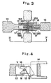
- constricting plates 16A, 16B projecting forwardly beyond the ends of the abutment portions 13A, 13b are attached to the inner sides thereof near the blade 15. As shown in Fig. 4, the constricting plate 16 has a V-shaped cut-out V open in the forward direction, and a slender elongated slot M communicating with the apex of the V-shaped cut-out V.
- a cylinder 28 which receives pressure from a drive source, not shown, via a switching valve 29.
- the cylinder 28 has a piston rod attached to an aft member 27 of a frame 26.
- the frame 26 has a forward member 25 to which an ultrasonic generating device 24 is attached.
- An ultrasonic horn 12 projects forwardly from the ultrasonic generating device 24 via an amplifying device 23.
- the forward portion of the horn 12 is provided with a hole obtained by closing both sides of a groove, thereby forming upper and lower abutment portions 12A, 12B the end faces whereof define sealing faces which meet the abutment portions 13A, 13B of the anvil through the intermediary of the film to clamp and seal the same.
- Numerals 17, 17′ denote constricting plates which operate in advance of the aforementioned constricting plates 16A, 16B and constitute constricting means together therewith.
- the constricting plates 17, 17′ each of which includes a V-shaped cut-out and a slender elongated slot M1 communicating with the apex of the V-shaped cut-out for forming the constricted portion of the film, are supported so as to be slidable in the same directions as the reciprocating plates and are coupled to the reciprocating plates via springs in the unit U.
- the relationship between the constricting plates and reciprocating plates does not have a direct bearing upon the present invention and therefore is deleted from the drawings. In this connection, the state shown in Fig.
- FIG. 3 is one in which a constricted portion is being formed by the constricting plates 17, 17 constricting the flattened portion, with the horn 12 and anvil 13 being shown in abutting contact with the constricted portion.
- the blade 15 has not yet been advanced to sever the constricted portion.
- the ultrasonic horn 12 and the anvil 13 draw very near to the constricted portion of the film.
- the cylinder 28 is actuated by the switching valve 29 substantially at the starting point of the interval A-A to advance its piston, so that the ultrasonic horn 12 and anvil 13 come into abutting contact with the constricted portion of the film at a set contact pressure. The abutting contact continues over the interval A-A, as depicted in Fig. 5.
- the flattened portion 10A of the tubular body 10 is forced into the elongaged slots M of constricting plates 16A, 16B via the cut-outs V thereof when the anvil 13 approaches the ultrasonic horn 12, whereby the flattened portion is formed into a constricted portion B having a generally circular cross section.
- the constricted portion B (see Fig. 3) is sealed sufficiently at upper and lower positions by the ultrasonic horn 12 and anvil 13 under a contact pressure applied for a set period of time.
- a single projectile-shaped packaged article drops away the tubular body 10 and is delivered via a chute to an article receptacle or to a conveyor or the like which carries the packaged article to a subsequent process.
- the reciprocating plates 20, 30 are moved away from each other by rotation of the drive wheels 21, 31 along the pitch circles 23, 33, and operation of the cylinder 28 is switched over by the switching valve 29, whereby the elements constituting the unit U are retracted. The next cycle of operation then begins.
Landscapes
- Engineering & Computer Science (AREA)
- Mechanical Engineering (AREA)
- Containers And Plastic Fillers For Packaging (AREA)
- Package Closures (AREA)
Description
- This invention relates to a method and apparatus for forming a flat film made of synthetic resin into a tube, filling the tube with a liquid or highly viscous material continuously while the tube is being formed, and producing a projectile-shaped package constituted by the filled film tube.
- In the Japanese patent publication 59-26424 a method and apparatus to produce Projectile-shaped packages such as sausages or cheese sticks by filling a tubular film with the particular foodstuff, is described. The described method of manufacturing a package of this kind includes steps of forming a flat film of synthetic resin into a tubular shape, forming a tube by fusing overlapped longitudinal side edges of the film while the film is being formed into the tubular shape, filling the interior of the tube continuously with a material to be packaged to form a tubular body formed continuously by being stuffed with the material, squeezing the traveling tubular body intermittently at a predetermined time interval by a pair of rotating cylindrical rollers to form flattened portions by pushing aside the material where the tubular body is squeezed, constricting each flattened portion transversely of the tubular body, to form a constricted portion, to seal the same by means of an ultrasonic horn and anvil, by bringing them in abutting contact with the said constricted portion and finally severing the constricted portion.
- Although realising a seal by using ultrasonic waves constitutes a real improvement over sealing by means of Wireclips. Still, problems remain, as will now be set forth.
- (1) In an arrangement where the film is clamped between an anvil and ultrasonic horn to effect a seal by the application of ultrasonic waves, a large clamping force is required. However, if a large clamping force is applied with an impact, the anvil and horn cause pinholes to form in the film, and in many cases the pinholes remain even after the sealing operation. This tendency becomes pronounced at higher operating speeds.
- (2) Despite the clamping of the film by the anvil and horn and the application of the ultrasonic waves, the film is clamped for only a short period of time. Consequently, when the electrode is simply detached after the sealing operation, the terminus of the seal easily develops a pinhole caused by the internal pressure of the filled material or when a force is mechanically applied to the film.
- (3) When the film is constricted solely by upper and lower constricting devices, the constricted film between the devices spreads and unfolds. Then, when the film is clamped by the anvil and ultrasonic horn between the two constricting devices, there is a large disparity in the number of film overlaps from one location to another. As a result, pinholes readily form when ultrasonic sealing is applied. When it is attempted to achieve a perfect seal up to where there is the minimum number of overlaps, namely where only a two-ply overlap exists, the overall result is over-sealing. This results in tearing at the seal ends and the formation of pinholes. If the application of the ultrasonic waves is weakened, on the other hand, then the two-ply overlap will not be fused completely and the package will leak from this region.
- (4) When a cutter is introduced to sever the film during sealing, the cutting force stretches the end of the seal and causes a pinhole to form. In addition, the cutting operation is difficult to perform. If the cut is made before sealing, the folds in the film will become undone and pinholes will form for the reasons set forth in (3) above.
- Accordingly, an object of the present invention is to provide a filling an packaging method through which ultrasonic sealing can be performed stably and safely even at high operating speeds.
- Another object of the present invention is to provide an apparatus for practicing the abovementioned method.
- According to the present invention, the first object is attained by according to the state of the art, as cited herein before providing a filling and packaging method which comprises the steps of: continuously pulling a film made of synthetic resin from a roll thereof and forming the film into a tubular shape; fusing overlapping longitudinal edge portions of the film while the film is being formed into the tubular shape, thereby obtaining a tubular film; continuously filling the interior of the tubular film with a material to be packaged to form a tubular body and feeding the tubular body while it is being formed; squeezing the fed tubular body intermittently at a predetermined time interval by a pair of rotating cylindrical rollers to form flattened portions devoid of the material, thereafter constricting each flattened portion transversely of the tubular body to form a constricted portion; bringing an ultrasonic horn and an anvil into abutting contact with the constricted portion. The method being characterised in that said constricted portion is sealed ultrasonically by holding the ultrasonic horn and anvil in abutting contact with the constricted portion at a constant contact pressure for a set period of time needed for sealing said film, keeping the ultrasonic horn and anvil at said abutting contact position while the ultrasonic horn applies ultrasonic waves to the constricted portion.
- According to the present invention, the second object is attained by providing a filling and packaging apparatus to perform the method according to the invention which comprises according to the state of the art as cited hereinbefore: fusing means for fusing overlapping longitudinal edge portions of a film made of synthetic resin while the film is being continuously pulled from a roll thereof and formed into a tubular shape, thereby obtaining a tubular film; material supply means for continuously filling the interior of the tubular film with a material to be packaged, thereby forming a tubular body; feeding means for feeding the tubular body; squeezing means having a pair of rotating cylindrical rollers for squeezing the fed tubular body intermittently at a predetermined time interval to form flattened portions devoid of the material; constricting means for constricting each flattened portion transversely of the tubular body to form a constricted portion; sealing means comprising an ultrasonic horn and an anvil for coming into abutting contact with the constricted portion from respective sides thereof at two positions in the direction of feed; a pair of reciprocating plates arranged at positions on respective sides of the flattened portion transversely thereof for moving toward and away from each other in the transverse direction, the constricting means and the sealing means being arranged on the reciprocating plates and adapted to cooperate with each other when the reciprocating plates approach each other. The apparatus is characterised in that it further comprises means for moving the reciprocating plates toward and away from each other and for halting movement thereof for a set period of time needed for sealing the film when the ultasonic horn and anvil assume positions proximate the constricted portion; and pressurizing means for moving the ultrasonic horn and anvil relative to the reciprocating plates in order to bring them into abutting contact therewith at a set contact pressure substantially for the set period of time; and cutting means for cutting through the constricted portion between the two positions.
- Though the contact pressure may be held constant from the beginning to the end of contact, it is possible to adopt an arrangement in which the pressure is applied weakly temporarily at the beginning of contact and then increased and maintained at the increased level for a fixed period of time.
- Thus, in accordance with the present invention, the tubular body obtained by filling the tubular film with the material to be packaged is squeezed to form a flattened portion, the flattened portion is constricted and the resulting constricted portion is ultrasonically sealed. When the ultrasonic sealing step is performed, the two reciprocating plates carrying the ultrasonic horn and anvil are stopped at positions very close to each other so that the horn and anvil do not impact against the constricted portion of the film when contacting the same. This assures that the constricted portion will not be damaged to prevent the formation of pinholes or the like. Further, since the ultrasonic horn and anvil are maintained in a state where they apply a constant, set contact pressure to the constricted portion for the indicated set period of time, an optimum contact pressure and contact time can be obtained. As a result, the film develops neither pinholes nor any other flaws. This means improved product reliability with regard to quality over an extended period of time. This advantage becomes even more apparent and renders the invention far superior to the prior art when the filling and packaging apparatus is run at high speed. In other words, the invention makes high-speed operation possible while assuring product quality, thus contributing to improved mass production.
- Other features and advantages of the present invention will be apparent from the following description taken in conjunction with the accompanying drawings, in which like reference characters designate the same or similar parts throughout the figures thereof.
-
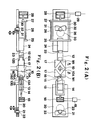
- Fig. 1 is a simplified schematic view showing the entirety of a filling and packaging apparatus embodying the present invention;
- Fig. 2(A) is a more detailed view of the apparatus of Fig. 1 as seen in the direction of the arrows II-II;
- Fig. 2(B) is a side view, partially broken away, illustrating a portion of the apparatus of Fig., 2(A);
- Fig. 3 is a detailed sectional view illustrating a sealing station in the apparatus of Fig. 1;
- Fig. 4 is a view of the sealing station of Fig. 3 as seen in the direction of arrows IV-IV; and
- Fig. 5 is a graphical representation showing the operating sequence of various elements in Fig. 4.
- A preferred embodiment of a filling and packaging apparatus according to the invention will now be described with reference to the accompanying drawings.
- As shown in Fig. 1 illustrating the overall arrangement of the apparatus, a supply pump 1 serving as means for supplying a material to fill a tubular film has a lower end to which a
nozzle 2 is connected. Located on one side of the apparatus is a roll 3 of coiledflat film 4 made of synthetic resin. Theflat film 4 is pulled off the roll 3 viaguide rolls 5 and is then formed into a tubular shape by a formingplate 6. The longitudinal edge portions of thefilm 4 thus shaped overlap each other and are sealingly fused together by a sealing electrode 7 serving as fusing means. Thefilm 4 is thus formed into a perfect tube. - The
tubular film 4 resulting from the foregoing process is pulled downwardly in Fig. 1 in continuous fashion by a set offilm feed rolls 8 constituting conveyance means. Meanwhile, the material to be packaged is fed out by the supply pump 1 and is continuously stuffed intotubular film 4 through thenozzle 2. Thetubular film 4 is thus filled with the material to be converted into a continuoustubular body 10. The latter is squeezed at a set time interval by squeezing means comprising a pair of rotating cylindrical rollers 9 (only one being shown), whereby the material filling the interior of the tube is partially pushed aside to form aflattened portion 10A. The latter is constricted transversely of the tube by constricting means and is ultrasonically sealed. - Since a characterizing feature of the invention resides in the sealing of the constricted portion, this will now be described in detail.
- In the apparatus of the invention, the sealing means is arranged on reciprocating plates, described below, together with the constricting means and cutting means and forms a single unit U together therewith. This unit is provided below the rotating squeezing rollers 9 and performs constricting, sealing and cutting operations while undergoing reciprocating motion.
- As shown in Figs. 2(A), (B), the
tubular body 10 obtained by filling the tubular film with the material is situated at the center of the unit U, with the elements constituting the unit U being arranged on both sides of theflattened portion 10A transversely thereof. The unit U includes tworeciprocating plates plates arcuate cam slots drive wheels pitch circles plates - Mounted on the
reciprocating plate 20 is acylinder 18 which receives pressure from a drive source, not shown, via aswitching valve 19. Thecylinder 18 has a piston rod to the forward end of which is fixedly secured aframe 14 carrying ablade 15 constituting the aforementioned cutting means. Ananvil 13 cooperating with an ultrasonic horn, described below, to form sealing means is integrally attached to thereciprocating plate 20 at a location in the space defined interiorly of theframe 14. Theanvil 13 has a a groove at its forward end which divides the anvil into twoabutment portions frame 14. Each of the twoabutment portions plates abutment portions 13A, 13b are attached to the inner sides thereof near theblade 15. As shown in Fig. 4, the constrictingplate 16 has a V-shaped cut-out V open in the forward direction, and a slender elongated slot M communicating with the apex of the V-shaped cut-out V. - Mounted on the aft portion of the other reciprocating
plate 30 is acylinder 28 which receives pressure from a drive source, not shown, via a switchingvalve 29. Thecylinder 28 has a piston rod attached to anaft member 27 of aframe 26. Theframe 26 has aforward member 25 to which anultrasonic generating device 24 is attached. Anultrasonic horn 12 projects forwardly from theultrasonic generating device 24 via anamplifying device 23. The forward portion of thehorn 12 is provided with a hole obtained by closing both sides of a groove, thereby forming upper andlower abutment portions abutment portions Numerals plates plates plates horn 12 andanvil 13 being shown in abutting contact with the constricted portion. In Fig. 3, theblade 15 has not yet been advanced to sever the constricted portion.) - The operation of the apparatus constructed as set forth above will now be described. The operating sequence will be discussed mainly in conjunction with Fig. 5.
- When the
drive wheels reciprocating plates ultrasonic horn 12 andanvil 13 approximate symmetrical sine waves in the positive and negative direction. However, since a portion of each of thecam grooves reciprocating plates ultrasonic horn 12 and theanvil 13 draw very near to the constricted portion of the film. Thecylinder 28 is actuated by the switchingvalve 29 substantially at the starting point of the interval A-A to advance its piston, so that theultrasonic horn 12 andanvil 13 come into abutting contact with the constricted portion of the film at a set contact pressure. The abutting contact continues over the interval A-A, as depicted in Fig. 5. - Since the forward portion of the
anvil 13 is provided with the two forward extending constrictingplates portion 10A of thetubular body 10 is forced into the elongaged slots M of constrictingplates anvil 13 approaches theultrasonic horn 12, whereby the flattened portion is formed into a constricted portion B having a generally circular cross section. At this time the constricted portion B (see Fig. 3) is sealed sufficiently at upper and lower positions by theultrasonic horn 12 andanvil 13 under a contact pressure applied for a set period of time. - In the latter half of the aforementioned set time period, the ultrasonic vibrations for sealing are halted and the
cylinder 18 is actuated by switchingvalve 19 to advance theframe 14, whereby the constricted portion B is severed by theblade 15 between the upper and lower sealed portions. - Thus, when the
reciprocating plates tubular body 10 and is delivered via a chute to an article receptacle or to a conveyor or the like which carries the packaged article to a subsequent process. - The
reciprocating plates drive wheels cylinder 28 is switched over by the switchingvalve 29, whereby the elements constituting the unit U are retracted. The next cycle of operation then begins.
Claims (2)
continuously pulling a film (4) made of synthetic resin from a roll (3) thereof and forming the film (4) into a tubular shape;
fusing overlapping longitudinal edge portions of the film while the film is being formed into the tubular shape, thereby obtaining a tubular film;
continuously filling the interior of said tubular film with a material to be packaged to form a tubular body (10) and feeding said tubular body (10) while it is being formed;
squeezing said fed tubular body (10) intermittently at a predetermined time interval by a pair of rotating cylindrical rollers (9) to form flattened portions (10A) devoid of the material;
thereafter constricting each flattened portion (10A) transversely of said tubular body (10) to form a constricted portion (B);
bringing an ultrasonic horn (12) and an anvil (13) into abutting contact with said constricted portion (B); characterised in that said constricted portion (B) is sealed ultrasonically by holding said ultrasonic horn (12) and anvil (13) in abutting contact with said constricted portion (B) at a constant contact pressure for a set period of time needed for sealing said film, keeping the ultrasonic horn (12) and anvil (13) at said abutting contact position, wile said ultrasonic horn (12) applies ultrasonic waves to said constricted portion (B).
fusing means (7) for using overlapping longitudinal edge portions of a film (4) made of synthetic resin while the film (4) is being continuously pulled from a roll (3) thereof and formed into a tubular shape, thereby obtaining a tubular film;
material supply means (1) for continuously filling the interior of the tubular film with a material to be packaged, thereby forming a tubular body (10);
feeding means (1,2) for feeding the tubular body (10);
squeezing means having a pair of rotating cylindrical rollers (9) for squeezing the fed tubular body (10) intermittently at a predetermined time interval to form flattened portions (10A) devoid of the material;
constricting means (16,17) for constricting each flattened portion (10A) transversely of the tubular body (10) to form a constricted portion (B);
sealing means comprising an ultrasonic horn (12) and an anvil (13) for coming into abutting contact with the constricted portion (B) from respective sides thereof at two positions in the direction of feed;
a pair of reciprocating plates (20,30) arranged at positions on respective sides of the flattened portion (10A) transversely thereof for moving toward and away from each other in the transverse direction, said constricting means (16,17) and said sealing means being arranged on said reciprocating plates (20,30) and adapted to cooperate with each other when said reciprocating plates (20,30) approach each other;
characterised in that if further comprises means for moving said reciprocating plates (20,30) toward and away from each other and for halting movement thereof for a set period of time needed for sealing said film, when said ultasonic horn (12) and anvil (13) assume positions proximate the constricted portion (B); and
pressurizing means (18,28) for moving said ultrasonic horn (12) and anvil (13) relative to said reciprocating plates (20,30) in order to bring them into abutting contact therewith at a set contact pressure substantially for said set period of time and cutting means (15) for cutting through the constricted portion (B) between the two postitions.
Applications Claiming Priority (2)
| Application Number | Priority Date | Filing Date | Title |
|---|---|---|---|
| JP88175/86 | 1986-04-18 | ||
| JP61088175A JPS62251325A (en) | 1986-04-18 | 1986-04-18 | Filling packaging method and device |
Publications (3)
| Publication Number | Publication Date |
|---|---|
| EP0242004A2 EP0242004A2 (en) | 1987-10-21 |
| EP0242004A3 EP0242004A3 (en) | 1988-11-02 |
| EP0242004B1 true EP0242004B1 (en) | 1991-10-23 |
Family
ID=13935569
Family Applications (1)
| Application Number | Title | Priority Date | Filing Date |
|---|---|---|---|
| EP87200705A Expired - Lifetime EP0242004B1 (en) | 1986-04-18 | 1987-04-15 | Filling and packaging method and apparatus therefor |
Country Status (6)
| Country | Link |
|---|---|
| US (1) | US4759170A (en) |
| EP (1) | EP0242004B1 (en) |
| JP (1) | JPS62251325A (en) |
| KR (1) | KR900003083B1 (en) |
| CN (1) | CN87103567B (en) |
| DE (1) | DE3773974D1 (en) |
Families Citing this family (62)
| Publication number | Priority date | Publication date | Assignee | Title |
|---|---|---|---|---|
| US4996825A (en) * | 1989-01-31 | 1991-03-05 | Kliklok Corporation | Combined blousing, stripping and sealing for bag forming and method |
| US5440860A (en) * | 1989-06-05 | 1995-08-15 | Schreiber Foods, Inc. | Method and apparatus for forming and hermetically sealing slices of food items |
| ZA915599B (en) * | 1990-08-13 | 1993-03-31 | Colgate Palmolive Co | Ultrasonic welding in pouch manufacture |
| DE4204396C2 (en) * | 1992-02-14 | 1996-09-05 | Natec Reich Summer Gmbh Co Kg | Device for packing a mass in a film tube |
| DE4204357C2 (en) * | 1992-02-14 | 2001-11-29 | Natec Reich | Device for packaging a product in a closed tubular film and for subsequently sealing this tubular film |
| IE922786A1 (en) * | 1992-02-28 | 1993-09-08 | Schreiber Foods | Method and apparatus for forming a slice of a food item¹having a heat tack seal |
| GB9314098D0 (en) * | 1993-07-08 | 1993-08-18 | Unilever Plc | Apparatus and methods for producing packets |
| US5533322A (en) * | 1994-03-11 | 1996-07-09 | Kliklok Corporation | Continuous vertical form-fill-seal packaging machine with constant motion carriage |
| DE4421366A1 (en) * | 1994-06-18 | 1995-12-21 | Spang & Brands Maschf | Method and device for portion-wise packaging of objects |
| CN1061292C (en) * | 1995-01-27 | 2001-01-31 | 铃木三次 | Apparatus for adhering and cutting synthetic resin packaging material |
| DE19505298A1 (en) * | 1995-02-16 | 1996-08-22 | Ips Int Packaging Syst | Ultrasonic sealing |
| US5861185A (en) * | 1996-08-22 | 1999-01-19 | Mars, Incorporated | Ultrasonic forming of confectionery products |
| US5871783A (en) * | 1996-08-22 | 1999-02-16 | Mars, Incorporated | Apparatus for ultrasonically forming confectionery products |
| US5871793A (en) | 1996-11-27 | 1999-02-16 | Mars Incorporated | Puffed cereal cakes |
| JP3880111B2 (en) * | 1996-11-28 | 2007-02-14 | 四国化工機株式会社 | Cutting device for filling and packaging machine |
| ES2152126B1 (en) * | 1997-04-02 | 2001-08-01 | Intermas Nets Sa | PROCEDURE FOR PACKING A PRODUCT IN PLASTIC MATERIAL TUBULAR BAGS AND CORRESPONDING BAG. |
| DE19742213C2 (en) * | 1997-09-24 | 2001-10-25 | Poly Clip System Gmbh & Co Kg | Process for closing tubular or bag-shaped packaging casings and closing device |
| JP4152464B2 (en) * | 1997-12-05 | 2008-09-17 | 株式会社クレハ | Cylindrical package, manufacturing method thereof and manufacturing apparatus thereof |
| US20020127310A1 (en) * | 1998-12-07 | 2002-09-12 | Capodieci Roberto A. | Cereal food product and method |
| US6265002B1 (en) | 1998-12-18 | 2001-07-24 | Kustner Industries S.A. | Non-hermetic seal for individually wrapped food items |
| US6368647B1 (en) * | 1998-12-29 | 2002-04-09 | Mars, Incorporated | Ultrasonically activated continuous slitter apparatus and method |
| DE19902827C1 (en) * | 1999-01-15 | 2000-06-08 | Hielscher Gmbh | Precision adjustment of clearance between sonotrode and cutting tool when cutting and/or welding sheet materials |
| JP4316053B2 (en) * | 1999-07-05 | 2009-08-19 | 四国化工機株式会社 | Ultrasonic sealing device |
| TW503203B (en) * | 2000-03-13 | 2002-09-21 | Fujishiro Kabushiki Kaisha | Packed article, apparatus and method for making the same |
| ATE352208T1 (en) * | 2000-08-10 | 2007-02-15 | Beliera Raul Oreste | DEVICE AND METHOD FOR PACKAGING PASTY, LIQUID OR SEMI-LIQUID PRODUCTS |
| EP1188672A1 (en) * | 2000-09-18 | 2002-03-20 | Mars B.V. | Method and device for packaging a food product, such as a candy, as well as a packaged candy |
| WO2002043960A1 (en) * | 2000-12-01 | 2002-06-06 | Stanhope Products Company | Improved ultrasonic weld pattern for adsorbent containing package |
| US6574944B2 (en) * | 2001-06-19 | 2003-06-10 | Mars Incorporated | Method and system for ultrasonic sealing of food product packaging |
| US6655948B2 (en) | 2001-08-31 | 2003-12-02 | Mars, Incorporated | System of ultrasonic processing of pre-baked food product |
| US6635292B2 (en) | 2001-10-26 | 2003-10-21 | Mars, Incorporated | Ultrasonic rotary forming of food products |
| ES2265477T3 (en) | 2001-12-12 | 2007-02-16 | Tna Australia Pty Limited | HERMETICO ROTARY CLOSURE AND SEPARATOR ASSEMBLY FOR A PACKING MACHINE. |
| JP4542796B2 (en) * | 2004-02-17 | 2010-09-15 | 株式会社クレハ | Package manufacturing apparatus, package manufacturing method, and package |
| US7137235B2 (en) * | 2004-10-12 | 2006-11-21 | Bostik Sa | Device and method for packaging in block form a sheathed hot-melt adhesive product |
| US20080268271A1 (en) * | 2004-10-12 | 2008-10-30 | Bostik Sa | Device and Method for Packaging in Block form a Sheathed Hot-Melt Adhesive Product |
| KR100687445B1 (en) * | 2005-06-21 | 2007-02-27 | 김주식 | Water pack manufacturing method and water pack |
| DE102005047507A1 (en) * | 2005-10-04 | 2007-04-12 | H.E.T. - Anke Filtertechnik Gmbh | Method and device for closing plastic bags |
| US20080307937A1 (en) * | 2007-06-15 | 2008-12-18 | Walter Neal Simmons | Device and method for producing film packages |
| JP4558805B2 (en) * | 2008-01-28 | 2010-10-06 | 株式会社クレハ | Cylindrical package manufacturing equipment |
| DE202009012907U1 (en) * | 2009-09-25 | 2011-02-10 | Hastamat Verpackungstechnik Gmbh | Tubular bag machine for producing and filling tubular bags |
| DE102010021838A1 (en) * | 2010-05-28 | 2011-12-01 | Hochland Se | Method and device for the portioned packaging of a food mass |
| JP5554727B2 (en) * | 2010-12-14 | 2014-07-23 | 株式会社イシダ | Goods transfer device |
| JP5926497B2 (en) * | 2011-05-11 | 2016-05-25 | 株式会社イシダ | Bag making and packaging machine |
| JP5684645B2 (en) * | 2011-05-11 | 2015-03-18 | 株式会社イシダ | Bag making and packaging machine |
| CN103895891B (en) * | 2012-12-26 | 2016-01-06 | 株式会社吴羽 | Cylindrical body manufacturing installation |
| BR112017025483A2 (en) * | 2015-06-22 | 2018-08-07 | Tetra Laval Holdings & Finance | tailored arrangement and method for packaging a liquid consumable product |
| EP3330190A1 (en) * | 2016-12-02 | 2018-06-06 | Swedish Match North Europe AB | Method and arrangement for portion-packing of an oral pouched snuff product |
| CN107352062A (en) * | 2017-07-05 | 2017-11-17 | 北京洋航科贸有限公司 | A kind of emulsified explosive charging machine |
| CN107826322A (en) * | 2017-11-24 | 2018-03-23 | 成都经纬机械制造有限公司 | Tight packing machine is sealed in a kind of anti-material folding |
| JP6307660B1 (en) * | 2017-12-13 | 2018-04-04 | ユニ・チャーム株式会社 | Ultrasonic sealing method and ultrasonic sealing device |
| JP6286611B1 (en) * | 2017-12-13 | 2018-02-28 | ユニ・チャーム株式会社 | Ultrasonic sealing method and ultrasonic sealing device |
| JP6307659B1 (en) * | 2017-12-13 | 2018-04-04 | ユニ・チャーム株式会社 | Ultrasonic sealing method and ultrasonic sealing device |
| CN108016641A (en) * | 2017-12-15 | 2018-05-11 | 北京航天东方科技发展有限公司 | A kind of automatic filling clipper |
| JP2019104224A (en) * | 2018-02-23 | 2019-06-27 | ユニ・チャーム株式会社 | Ultrasonic sealing method and ultrasonic sealing device |
| JP2019104225A (en) * | 2018-02-23 | 2019-06-27 | ユニ・チャーム株式会社 | Ultrasonic sealing method and ultrasonic sealing device |
| CN108394592B (en) * | 2018-05-09 | 2024-04-30 | 北京航天东方科技发展有限公司 | Ligation sealing mechanism of automatic vertical filling packing machine without aluminum buckle |
| CN109625371A (en) * | 2018-12-17 | 2019-04-16 | 昆山迈格金相机械设备有限公司 | A kind of packaging bag forming machine |
| CN110301268B (en) * | 2019-07-10 | 2021-08-31 | 南宁学院 | A watermelon seedling planting bag and its bagging machine |
| US11447281B2 (en) * | 2020-02-14 | 2022-09-20 | Lako Tool & Manufacturing, Inc. | Modular stand-alone ultrasonic sealing system |
| CN113184291A (en) * | 2021-05-08 | 2021-07-30 | 江苏仅一联合智造有限公司 | Longitudinal sealing traction and heat sealing device |
| US20240002092A1 (en) * | 2022-06-30 | 2024-01-04 | Hon Bouw Co., Ltd. | Bag Clamping and Sealing Machine |
| CN117585265B (en) * | 2023-05-19 | 2025-11-25 | 淮南市金德实业有限公司 | An anchoring agent packaging device and method |
| CN118370330B (en) * | 2024-05-25 | 2025-09-12 | 陕西好利来食品有限公司 | A cake filling machine |
Citations (1)
| Publication number | Priority date | Publication date | Assignee | Title |
|---|---|---|---|---|
| JPS5926424A (en) * | 1982-08-02 | 1984-02-10 | 旭化成株式会社 | Packing method |
Family Cites Families (15)
| Publication number | Priority date | Publication date | Assignee | Title |
|---|---|---|---|---|
| NL292674A (en) * | 1961-10-11 | 1900-01-01 | ||
| US3324621A (en) * | 1963-06-10 | 1967-06-13 | Mayer & Co Inc O | Packaging machine |
| DE1511674A1 (en) * | 1966-11-09 | 1969-08-28 | Kalle Ag | Method and device for the continuous production of tubular packs |
| US3432980A (en) * | 1967-06-07 | 1969-03-18 | Mayer & Co Inc O | Method and apparatus for making a clip and seal package |
| US3611657A (en) * | 1968-09-27 | 1971-10-12 | Kureha Chemical Ind Co Ltd | Continuously operating automatic filling machine |
| US3667594A (en) * | 1969-11-20 | 1972-06-06 | Dow Chemical Co | Closure for film packages and method of making same |
| US3780488A (en) * | 1969-11-20 | 1973-12-25 | Dow Chemical Co | Closure for film packages and method of making same |
| JPS5211270B1 (en) * | 1970-02-12 | 1977-03-30 | ||
| SE341610B (en) * | 1970-07-03 | 1972-01-10 | Sobrefina Sa | |
| DE2812137C2 (en) * | 1978-03-20 | 1985-06-27 | Jagenberg-Werke AG, 4000 Düsseldorf | Method and device for producing a web seam seal on a folding box, in particular with a gable, made of cardboard material coated with thermoplastic by ultrasonic welding |
| DE2922834A1 (en) * | 1979-06-06 | 1980-12-11 | Niepmann Ag Walchwil | Packing fluids, slurries, solids, in thermoplastic film hoses - using two ultrasonic welders forming vertical and horizontal seams |
| US4506494A (en) * | 1983-04-18 | 1985-03-26 | Mamoru Shimoyama | Packed bag cutter |
| US4517790A (en) * | 1984-02-27 | 1985-05-21 | Frito-Lay, Inc. | Apparatus and method for ultrasonic sealing of packages |
| JPS60154206U (en) * | 1984-03-27 | 1985-10-15 | オリヒロ株式会社 | Horizontal seal wrinkle prevention device |
| JPH0330242Y2 (en) * | 1984-11-27 | 1991-06-26 |
-
1986
- 1986-04-18 JP JP61088175A patent/JPS62251325A/en active Granted
-
1987
- 1987-04-08 US US07/035,985 patent/US4759170A/en not_active Expired - Fee Related
- 1987-04-15 DE DE8787200705T patent/DE3773974D1/en not_active Expired - Fee Related
- 1987-04-15 EP EP87200705A patent/EP0242004B1/en not_active Expired - Lifetime
- 1987-04-16 CN CN87103567A patent/CN87103567B/en not_active Expired
- 1987-04-16 KR KR1019870003665A patent/KR900003083B1/en not_active Expired
Patent Citations (1)
| Publication number | Priority date | Publication date | Assignee | Title |
|---|---|---|---|---|
| JPS5926424A (en) * | 1982-08-02 | 1984-02-10 | 旭化成株式会社 | Packing method |
Also Published As
| Publication number | Publication date |
|---|---|
| KR900003083B1 (en) | 1990-05-07 |
| JPH0567496B2 (en) | 1993-09-27 |
| CN87103567B (en) | 1988-08-10 |
| EP0242004A2 (en) | 1987-10-21 |
| DE3773974D1 (en) | 1991-11-28 |
| US4759170A (en) | 1988-07-26 |
| KR870009914A (en) | 1987-11-30 |
| JPS62251325A (en) | 1987-11-02 |
| EP0242004A3 (en) | 1988-11-02 |
| CN87103567A (en) | 1987-11-18 |
Similar Documents
| Publication | Publication Date | Title |
|---|---|---|
| EP0242004B1 (en) | Filling and packaging method and apparatus therefor | |
| US4387547A (en) | Device for manufacturing packages filled with liquid | |
| US4517790A (en) | Apparatus and method for ultrasonic sealing of packages | |
| EP0915015B1 (en) | Method of controlling end seal time in bag-making, filling and packaging machine | |
| US2200971A (en) | System for making, filling, and sealing containers | |
| US4986054A (en) | Fill tube spreader | |
| US4856259A (en) | Appratus for sealing and severing a web of film | |
| US3314210A (en) | Process and a device for manufacturing packages | |
| JPH07172403A (en) | Vertically filling and packing apparatus | |
| US3543467A (en) | Method and apparatus for packaging with a movable mandrel | |
| US3221469A (en) | Method and apparatus for forming tetrahedron shaped packages | |
| US3082586A (en) | Packaging machine | |
| US4994137A (en) | Bag making machine sealer slitter apparatus | |
| US3681890A (en) | Method of and apparatus for forming packages with tear tabs | |
| US3425185A (en) | Production of sealed filled envelopes | |
| US3552081A (en) | Method and apparatus for packaging with a movable mandrel and movable sealing jaws | |
| JP4753899B2 (en) | Automatic packaging machine | |
| US3483061A (en) | Method and apparatus for producing bags from tubular film | |
| US4131503A (en) | Method and apparatus for sealing and cutting thermoplastic material | |
| US3419206A (en) | Tubular food package with tear strip | |
| US6640519B1 (en) | Method and apparatus for producing bags having a recloseable fastener | |
| GB2256415A (en) | Method and apparatus for making triangular pyramidal tea bags | |
| JP2646514B2 (en) | Sealing device in filling and packaging machine | |
| US3586579A (en) | Apparatus for forming tearing tape pieces on a web of packaging film to be used in successively forming individual tubular packages | |
| US2475359A (en) | Container forming machine and method |
Legal Events
| Date | Code | Title | Description |
|---|---|---|---|
| PUAI | Public reference made under article 153(3) epc to a published international application that has entered the european phase |
Free format text: ORIGINAL CODE: 0009012 |
|
| AK | Designated contracting states |
Kind code of ref document: A2 Designated state(s): DE GB NL |
|
| PUAL | Search report despatched |
Free format text: ORIGINAL CODE: 0009013 |
|
| AK | Designated contracting states |
Kind code of ref document: A3 Designated state(s): DE GB NL |
|
| 17P | Request for examination filed |
Effective date: 19890316 |
|
| 17Q | First examination report despatched |
Effective date: 19900522 |
|
| GRAA | (expected) grant |
Free format text: ORIGINAL CODE: 0009210 |
|
| AK | Designated contracting states |
Kind code of ref document: B1 Designated state(s): DE GB NL |
|
| REF | Corresponds to: |
Ref document number: 3773974 Country of ref document: DE Date of ref document: 19911128 |
|
| PG25 | Lapsed in a contracting state [announced via postgrant information from national office to epo] |
Ref country code: NL Effective date: 19920207 |
|
| PLBE | No opposition filed within time limit |
Free format text: ORIGINAL CODE: 0009261 |
|
| STAA | Information on the status of an ep patent application or granted ep patent |
Free format text: STATUS: NO OPPOSITION FILED WITHIN TIME LIMIT |
|
| 26N | No opposition filed | ||
| NLXE | Nl: other communications concerning ep-patents (part 3 heading xe) |
Free format text: A REQUEST FOR RESTORATION TO THE PRIOR STATE HAS BEEN FILED ON 930208 |
|
| NLXE | Nl: other communications concerning ep-patents (part 3 heading xe) |
Free format text: THE REQUEST FOR RESTORATION TO THE PRIOR STATE AS PROVIDED FOR IN ARTICLE 17A OF THE PATENTS ACT HAS BEEN WITHDRAWN ON 930312 |
|
| PGFP | Annual fee paid to national office [announced via postgrant information from national office to epo] |
Ref country code: GB Payment date: 19990415 Year of fee payment: 13 |
|
| PGFP | Annual fee paid to national office [announced via postgrant information from national office to epo] |
Ref country code: DE Payment date: 19990426 Year of fee payment: 13 |
|
| PG25 | Lapsed in a contracting state [announced via postgrant information from national office to epo] |
Ref country code: GB Free format text: LAPSE BECAUSE OF NON-PAYMENT OF DUE FEES Effective date: 20000415 |
|
| GBPC | Gb: european patent ceased through non-payment of renewal fee |
Effective date: 20000415 |
|
| PG25 | Lapsed in a contracting state [announced via postgrant information from national office to epo] |
Ref country code: DE Free format text: LAPSE BECAUSE OF NON-PAYMENT OF DUE FEES Effective date: 20010201 |