EP0241981A1 - Method and apparatus for mounting concaves - Google Patents
Method and apparatus for mounting concaves Download PDFInfo
- Publication number
- EP0241981A1 EP0241981A1 EP87200624A EP87200624A EP0241981A1 EP 0241981 A1 EP0241981 A1 EP 0241981A1 EP 87200624 A EP87200624 A EP 87200624A EP 87200624 A EP87200624 A EP 87200624A EP 0241981 A1 EP0241981 A1 EP 0241981A1
- Authority
- EP
- European Patent Office
- Prior art keywords
- concave
- mounting
- frame
- mounting frame
- members
- Prior art date
- Legal status (The legal status is an assumption and is not a legal conclusion. Google has not performed a legal analysis and makes no representation as to the accuracy of the status listed.)
- Granted
Links
Images

Classifications
-
- A—HUMAN NECESSITIES
- A01—AGRICULTURE; FORESTRY; ANIMAL HUSBANDRY; HUNTING; TRAPPING; FISHING
- A01F—PROCESSING OF HARVESTED PRODUCE; HAY OR STRAW PRESSES; DEVICES FOR STORING AGRICULTURAL OR HORTICULTURAL PRODUCE
- A01F12/00—Parts or details of threshing apparatus
- A01F12/18—Threshing devices
- A01F12/28—Devices for adjusting the concaves
-
- A—HUMAN NECESSITIES
- A01—AGRICULTURE; FORESTRY; ANIMAL HUSBANDRY; HUNTING; TRAPPING; FISHING
- A01F—PROCESSING OF HARVESTED PRODUCE; HAY OR STRAW PRESSES; DEVICES FOR STORING AGRICULTURAL OR HORTICULTURAL PRODUCE
- A01F7/00—Threshing apparatus
- A01F7/02—Threshing apparatus with rotating tools
- A01F7/06—Threshing apparatus with rotating tools with axles in line with the feeding direction ; Axial threshing machines
Definitions
- the present invention relates generally to axial flow combines and, particularly, to an improved method and apparatus for mounting a concave on a mounting frame for selective positioning relative to the threshing and separating rotor.
- the feeder and feed plate must be removed from the combine before the concave front supports can be unbolted and then the concaves removed through the front of the combine.
- the installation of the concaves involves a reversal of this procedure.
- an axial flow combine harvester which comprises : - a pair of transversely spaced apart side sheets, at least one of which includes an access opening; - at least one threshing and separating rotor extending in a generally longitudinal direction between the side sheets; - a concave peripherally positioned relative to the at least one rotor; and - a mounting frame supporting the concave relative to the corresponding rotor; the concave being detachably mounted to the mounting frame by mounting means positioned generally at the transversely opposite longitudinal sides of said concave and the mounting means provided generally at the longitudinal side of the concave facing away from the access opening in the at least one side sheet being formed by cooperating members provided on both the concave and the mounting frame, and which is characterized in that : the cooperating mounting members generally at the longitudinal side of the concave facing away from said access opening permit engagement thereof generally in a transverse direction whereby the concave can be mounted on the mounting frame in a transverse direction through said access opening
- the concave comprises a pair of transversely extending, longitudinally spaced apart concave frame members.
- a pair of cooperating mounting members is associated with each on of said concave frame members.
- Each pair of cooperating mounting members preferably is in the form of a cooperating mounting pin and yoke; the pin being affixed to either one of both the mounting frame and the concave and the yoke being provided on the other one of both said mounting frame and concave and further being positioned such that engagement thereof with the corresponding mounting pin can be effected by moving the concave in the transverse direction.
- the mounting pins are affixed to the mounting frame and the yokes are connected to the concave frame members.
- Retaining links preferably also are mounted on the mounting pins in conjunction with the concave yokes and are connected to the concave frame members to retain the concave on the mounting pins during operation of the combine.
- Support plates carried by the mounting frame can be utilized to support the weight of the concave during the mounting procedure.
- a method of installing a concave on an axial flow combine harvester comprising the steps of : - moving the concave in a transverse direction toward the first mounting means to effect engagement between the first and further mounting means, said further mounting means being rotatably movable relative to the first mounting means when engaged to permit movement of the concave relative to the rotor; - fixing at least one retaining link between the mounting frame and the concave to prevent disengagement of the further mounting means with the first mounting means during operation of the combine harvester; and - connecting at least one connecting link between the mounting frame and the concave at a distant location from the cooperating first and further mounting means to support the concave (20) on the mounting frame and control the ang
- a side mount concave mounting apparatus for use in an axial flow combine utilizing a longitudinally extending threshing and separating rotor is provided and which greatly reduces the time and work required to remove and/or install the concave to the extent that the feeder and feed plate do not need to be removed from the combine in order to remove and/or install said concave.
- This concave mounting apparatus is durable in construction, inexpensive of manufacture, carefree of maintenance, facile in assemblage and simple and effective in use.
- a left side elevational view of a crop harvesting machine commonly referred to as an axial flow combine harvester, incorporating the principles of the instant invention, can be seen.
- Any left and right references are used as a matter of convenience and are determined by standing at the rear of the machine and facing in the direction of operative travel.
- the combine 10 is mounted on a wheeled frame 12 to mobilely support the combine 10 over the ground G for the harvesting of crops therefrom.
- a header 13 is mounted on the forward periphery of the combine 10 to engage and gather crop material from the ground G and consolidate it into a feederhouse structure 14.
- the feederhouse 14 conveys a flow of crop material into the infeed area 16 of the threshing and separating rotors 15.
- the concave 20 is provided with at least two longitudinally spaced frame members 22,23, the forwardmost one of which is designated by the reference numeral 23 and which carry a plurality of longitudinally extending rub bars 24 radially positioned relative to the rotor 15. Crop material entering between the rotor 15 and the concave 20 is rubbed between the rasp bar assemblies 18 and the rub bars 24 to separate grain from the crop material.
- the concave 20 is mounted on an adjustable mounting frame 25 to permit adjustment of the concave 20 relative to the rotor 15 as is described in greater detail in U.S. Patent No. 4, 375,221, the description of which is incorporated herein by reference.
- Figs. 2 and 3 the structure of the instant invention can best be seen and will be described hereinafter with reference to the left hand concave; the structure and operation of the right hand concave being identical thereto.
- the forwardmost concave frame member 23 is shown in Fig. 3
- the rearwardmost concave frame member 22 is constructed in a similar manner and the description given below with respect to the forwardmost frame member 23 is equally applicable to the structure and operation of this rearwardmost concave frame member 22.
- the description given below with respect to the left hand concave equally applies to the right hand concave.
- each concave 20 is provided with a clevis mechanism 27 in the form of open yokes 28 affixed to the frame member 22,23 in a permanent fashion.
- Each yoke 28 is engageable with a mounting pin 29 projecting in a longitudinal direction from the mounting frame 25 and is oriented in such a manner as to be engageable with said mounting pin 29 when the concave 20 is moved in a transverse direction toward the mounting pins 29.
- a retaining link 30 is also mountable on each mounting pin 29 and connectable to the corresponding concave frame member 22,23 by fasteners 32 in a manner such that these retaining links 30 are selectively disconnectable from the corresponding frame members 22,23.
- two transversely spaced apart fasteners are utilized for coupling each retaining link 30 to the corresponding frame member 22, 23 to guarantee a secure engagement between the corresponding pins 29 and yokes 28.
- These spaced apart fasteners preferably are positioned proximate to the outboard ends of the retaining links 30 and concave frame members 22, 23 to facilitate access thereto through the respective access openings 42 in the combine side sheets 43.
- An adjustable connecting link 35 interconnecting the mounting frame 25 and an outboard portion of each one of the frame members 22,23 by fasteners 36 controls the rotative position of the concave 20 about the mounting pins 29. It can be seen that an adjustment of the length of the connecting links 35 will affect a rotation of the yokes 28 about the mounting pins 29 on which they are mounted, thereby changing the relative position of the concave 20 with respect to the corresponding rotor 15 in a manner separate from the adjustment of the mounting frame 25.
- the mounting frame 25 is provided with plate members 40 positioned beneath the location of the respective concave frame members 22,23 to carry the weight of the concave 20 during the installation of the concave 20 as will be described in greater detail below.
- the plate members 20 do not support the weight of the concave 20 after the concave 20 has been mounted on the mounting frame 25; the respective concave frame members 22,23 being spaced above the corresponding plate members 40 to permit a rotative movement thereof about the mounting of the yokes 28 on the mounting pins 29 through an adjustment of the connecting links 35.
- the method of installing the side mount concaves 20 is described below with particular reference being made to Figs. 2 and 3.
- the retaining links 30 are first mounted on the mounting pins 29 by positioning the retaining links 30 such that the mounting pins 29 are inserted through the corresponding bores 31.
- the concave 20 is then inserted through the access opening 42 and, using the plates 40 to temporarily support the weight of the concave 20, the frame members, 22,23 are positioned so that the yokes 28 can be guided onto the mounting pins 29.
- the fasteners 32 are then inserted through the respective frame members 22,23 and the corresponding retaining links 30 to fix the retaining links 30 to the concave frame members 22,23.
- the adjustable connecting links 35 are then connected to the respective concave frame members 22,23 by the fasteners 36. Any fine adjustments required of the concave 20 to position it relative to the corresponding threshing and separating rotor 15 can be obtained by adjusting the relative lengths of the connecting links 35. As seen in Fig. 2, once the concave 20 is supported on the mounting pins 29 and the connecting links 35, the respective frame members 22,23 are lifted off the plate members 40.
- the purpose of the retaining links 30 is to resist forces imposed on the concaves 20 to prevent the yokes 28 from becoming disengaged from the mounting pins 29 during normal harvesting operation of the combine 10.
- the retaining links 30 can be unbolted from the concave frame members 22,23 to permit an easy removal of the concaves 20 through the transversely positioned openings 42 in the side sheets 43 of the combine 10. This structure eliminates the need to remove the infeed mechanism 19 located forwardly of the threshing concaves 20 in order to remove, respecively install said concaves 20. Removal of the concaves 20, such as needed for changing the concaves 20, can be accomplished in the reverse manner indicated above for installation of the concaves 20.
- the connecting links 35 can be disconnected from the concave frame members 22,23 and the concaves 20 rested upon the plate members 40.
- a disconnection of the retaining links 30 from the frame members 22,23 will permit the yokes 28 to be disengaged from the mounting pins 29 and the concaves 20 to be removed through the openings 42 in the side sheets 43.
- the pins 29 may be provided on the concave frame members 22, 23 rather than on the mounting frame 25.
- the yokes 28 obviously should be affixed to the mounting frame 25.
- the retaining links 30 still can be pivotally mounted on the mounting frame 25, preferably generally co-axially with the pins 29 when the concave 20 is mounted on this mounting frame 25.
- the retaining links can be detachably connectable to the respective concave frame members 22, 23 by fasteners 32.
- the retaining link 30 also may be pivotally mounted on the mounting pins 29 on the concave frame members 22, 23 and be detachably connectable by fastener means 32 to the mounting frame 25.
- the invention has been described hereabove in connection with a twin rotor axial flow combine. However, it will be clear that this invention equally well is applicable on a single rotor axial flow combine.
Abstract
Description
- The present invention relates generally to axial flow combines and, particularly, to an improved method and apparatus for mounting a concave on a mounting frame for selective positioning relative to the threshing and separating rotor.
- Axial flow combines of the type shown and described in U.S. Patent No. 4,249,543, currently require a considerable amount of time and effort to remove and install the concaves on its mounting frame proximate to the threshing and separating rotors. In such combine harvesters, the feeder and feed plate must be removed from the combine before the concave front supports can be unbolted and then the concaves removed through the front of the combine. The installation of the concaves involves a reversal of this procedure.
- It is the object of the present invention to provide an axial flow combine harvester having at least one concave which is removably mounted relative to a threshing and separating rotor and of which the removal, respectively the installation has been made substantially more easy to accomplish.
- According to the invention, an axial flow combine harvester is provided which comprises :
- a pair of transversely spaced apart side sheets, at least one of which includes an access opening;
- at least one threshing and separating rotor extending in a generally longitudinal direction between the side sheets;
- a concave peripherally positioned relative to the at least one rotor; and
- a mounting frame supporting the concave relative to the corresponding rotor; the concave being detachably mounted to the mounting frame by mounting means positioned generally at the transversely opposite longitudinal sides of said concave and the mounting means provided generally at the longitudinal side of the concave facing away from the access opening in the at least one side sheet being formed by cooperating members provided on both the concave and the mounting frame, and which is
characterized in that :
the cooperating mounting members generally at the longitudinal side of the concave facing away from said access opening permit engagement thereof generally in a transverse direction whereby the concave can be mounted on the mounting frame in a transverse direction through said access opening. - Preferably, the concave comprises a pair of transversely extending, longitudinally spaced apart concave frame members. A pair of cooperating mounting members is associated with each on of said concave frame members. Each pair of cooperating mounting members preferably is in the form of a cooperating mounting pin and yoke; the pin being affixed to either one of both the mounting frame and the concave and the yoke being provided on the other one of both said mounting frame and concave and further being positioned such that engagement thereof with the corresponding mounting pin can be effected by moving the concave in the transverse direction.
- In a preferred embodiment, the mounting pins are affixed to the mounting frame and the yokes are connected to the concave frame members. Retaining links preferably also are mounted on the mounting pins in conjunction with the concave yokes and are connected to the concave frame members to retain the concave on the mounting pins during operation of the combine. Support plates carried by the mounting frame can be utilized to support the weight of the concave during the mounting procedure.
- According to another aspect of the invention, a method of installing a concave on an axial flow combine harvester is provided; said concave being mountable on a mounting frame provided within the combine harvester and carrying first mounting means which are cooperable with further mounting means on the concave for supporting the concave in cooperative association with a threshing and separating rotor; said method being characterized in that it comprises the steps of :
- moving the concave in a transverse direction toward the first mounting means to effect engagement between the first and further mounting means, said further mounting means being rotatably movable relative to the first mounting means when engaged to permit movement of the concave relative to the rotor;
- fixing at least one retaining link between the mounting frame and the concave to prevent disengagement of the further mounting means with the first mounting means during operation of the combine harvester; and
- connecting at least one connecting link between the mounting frame and the concave at a distant location from the cooperating first and further mounting means to support the concave (20) on the mounting frame and control the angular position of the concave relative to the rotor. - Thus, in summary, a side mount concave mounting apparatus for use in an axial flow combine utilizing a longitudinally extending threshing and separating rotor is provided and which greatly reduces the time and work required to remove and/or install the concave to the extent that the feeder and feed plate do not need to be removed from the combine in order to remove and/or install said concave. This concave mounting apparatus is durable in construction, inexpensive of manufacture, carefree of maintenance, facile in assemblage and simple and effective in use.
- The advantages of this invention will become apparent upon consideration of the following detailed disclosure of the invention, especially when taken in conjunction with the accompanying drawings, wherein:
- Fig. 1 is a left side elevational view of a combine harvester incorporating the principles of the instant invention, a portion of the side sheet of the combine being broken away to more clearly show the relative positions of the threshing and separating rotors and cooperatively mounted concaves;
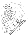
- Fig. 2 is an enlarged partial cross-sectional view taken along lines 2-2 of Fig. 1, looking along the longitudinally extending axis of the threshing and separating rotor, the portions of the infeed structure in front of the left hand threshing rotor portion being broken away to more clearly show the structure and relationships utilized in the side mount concaves forming the instant invention; and
- Fig. 3 is an enlarged exploded view of the forwardmost portion of the left hand concave identifying the manner in which the concave and retaining link are mounted on the adjustable mounting frame.
- Referring now to the drawings and, particularly, to Fig. 1, a left side elevational view of a crop harvesting machine, commonly referred to as an axial flow combine harvester, incorporating the principles of the instant invention, can be seen. Any left and right references are used as a matter of convenience and are determined by standing at the rear of the machine and facing in the direction of operative travel. The
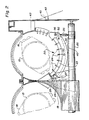
combine 10 is mounted on a wheeled frame 12 to mobilely support thecombine 10 over the ground G for the harvesting of crops therefrom. Aheader 13 is mounted on the forward periphery of thecombine 10 to engage and gather crop material from the ground G and consolidate it into afeederhouse structure 14. Thefeederhouse 14 conveys a flow of crop material into the infeedarea 16 of the threshing and separatingrotors 15. The flow of crop material then passes into thethreshing area 17 between therotor 15 and the circumferentially mounted concave 20 where grain is threshed and separated from the crop material byrasp bar assemblies 18 cooperating with the concaves 20. While that the combine shown and described herein is a twin rotor axial flow combine, it will be clear to a person skilled in the art that the instant invention is equally applicable to a single rotor axial flow combine as well. - Referring now to Fig. 2, the relationship of a
rotor 15 and therasp bar assemblies 18 mounted thereon with respect to the corresponding concave 20 can best be seen. The concave 20 is provided with at least two longitudinally spacedframe members reference numeral 23 and which carry a plurality of longitudinally extendingrub bars 24 radially positioned relative to therotor 15. Crop material entering between therotor 15 and the concave 20 is rubbed between therasp bar assemblies 18 and therub bars 24 to separate grain from the crop material. The concave 20 is mounted on anadjustable mounting frame 25 to permit adjustment of the concave 20 relative to therotor 15 as is described in greater detail in U.S. Patent No. 4, 375,221, the description of which is incorporated herein by reference. - Referring now to Figs. 2 and 3, the structure of the instant invention can best be seen and will be described hereinafter with reference to the left hand concave; the structure and operation of the right hand concave being identical thereto. Although the forwardmost
concave frame member 23 is shown in Fig. 3, the rearwardmostconcave frame member 22 is constructed in a similar manner and the description given below with respect to theforwardmost frame member 23 is equally applicable to the structure and operation of this rearwardmostconcave frame member 22. Also, the description given below with respect to the left hand concave equally applies to the right hand concave. Theframe members clevis mechanism 27 in the form ofopen yokes 28 affixed to theframe member yoke 28 is engageable with a mountingpin 29 projecting in a longitudinal direction from themounting frame 25 and is oriented in such a manner as to be engageable with said mountingpin 29 when the concave 20 is moved in a transverse direction toward themounting pins 29. - A
retaining link 30 is also mountable on eachmounting pin 29 and connectable to the correspondingconcave frame member fasteners 32 in a manner such that theseretaining links 30 are selectively disconnectable from thecorresponding frame members retaining links 30, when connected to thecorresponding frame member yokes 28 on therespective mounting pin 29 and prevents the concave 20 from bouncing off themounting pins 29 during operation of thecombine 10. It will be noted that preferably two transversely spaced apart fasteners are utilized for coupling each retaininglink 30 to thecorresponding frame member corresponding pins 29 andyokes 28. These spaced apart fasteners preferably are positioned proximate to the outboard ends of theretaining links 30 andconcave frame members respective access openings 42 in thecombine side sheets 43. - An
adjustable connecting link 35 interconnecting themounting frame 25 and an outboard portion of each one of theframe members fasteners 36 controls the rotative position of the concave 20 about themounting pins 29. It can be seen that an adjustment of the length of the connectinglinks 35 will affect a rotation of theyokes 28 about themounting pins 29 on which they are mounted, thereby changing the relative position of the concave 20 with respect to thecorresponding rotor 15 in a manner separate from the adjustment of themounting frame 25. - The
mounting frame 25 is provided withplate members 40 positioned beneath the location of the respectiveconcave frame members plate members 20 do not support the weight of the concave 20 after the concave 20 has been mounted on themounting frame 25; the respectiveconcave frame members corresponding plate members 40 to permit a rotative movement thereof about the mounting of theyokes 28 on themounting pins 29 through an adjustment of theconnecting links 35. - Using the component parts of the concave and mounting structures as described above, the method of installing the
side mount concaves 20 is described below with particular reference being made to Figs. 2 and 3. To install the concave 20 on themounting frame 25, access to the interior of thecombine 10 can be gained through the access opening 42 in theside sheet 43 of thecombine 10 and opposite the mounting location of the concave 20 and which is normally covered by a hingeddoor 45. Theretaining links 30 are first mounted on themounting pins 29 by positioning theretaining links 30 such that themounting pins 29 are inserted through thecorresponding bores 31. The concave 20 is then inserted through the access opening 42 and, using theplates 40 to temporarily support the weight of the concave 20, the frame members, 22,23 are positioned so that theyokes 28 can be guided onto themounting pins 29. - The
fasteners 32 are then inserted through therespective frame members retaining links 30 to fix theretaining links 30 to theconcave frame members links 35 are then connected to the respectiveconcave frame members fasteners 36. Any fine adjustments required of the concave 20 to position it relative to the corresponding threshing and separatingrotor 15 can be obtained by adjusting the relative lengths of the connectinglinks 35. As seen in Fig. 2, once the concave 20 is supported on themounting pins 29 and the connectinglinks 35, therespective frame members plate members 40. - One skilled in the art will readily realize that the purpose of the retaining
links 30 is to resist forces imposed on the concaves 20 to prevent theyokes 28 from becoming disengaged from themounting pins 29 during normal harvesting operation of thecombine 10. The retaininglinks 30 can be unbolted from theconcave frame members concaves 20 through the transversely positionedopenings 42 in theside sheets 43 of thecombine 10. This structure eliminates the need to remove the infeedmechanism 19 located forwardly of thethreshing concaves 20 in order to remove, respecively install said concaves 20. Removal of theconcaves 20, such as needed for changing theconcaves 20, can be accomplished in the reverse manner indicated above for installation of theconcaves 20. - The connecting
links 35 can be disconnected from theconcave frame members plate members 40. A disconnection of the retaininglinks 30 from theframe members yokes 28 to be disengaged from the mountingpins 29 and theconcaves 20 to be removed through theopenings 42 in theside sheets 43. - It will be understood that changes in the details, materials, steps and arrangement of parts which have been described and illustrated to explain the nature of the invention will occur to and may be made by those skilled in the art upon a reading of this disclosure within the principles and scope of the invention. The foregoing description illustrates the preferred embodiment of the invention; however, concepts, as based upon the description may be employed in other embodiments without departing from the scope of the invention.
- As an example, it will be clear to a person skilled in the art that, in an alternative arrangement, the
pins 29 may be provided on theconcave frame members frame 25. In this case, theyokes 28 obviously should be affixed to the mountingframe 25. The retaining links 30 still can be pivotally mounted on the mountingframe 25, preferably generally co-axially with thepins 29 when the concave 20 is mounted on this mountingframe 25. As in the arrangement illustrated in the drawings, the retaining links can be detachably connectable to the respectiveconcave frame members fasteners 32. Alternatively, the retaininglink 30 also may be pivotally mounted on the mounting pins 29 on theconcave frame members frame 25. Also, the invention has been described hereabove in connection with a twin rotor axial flow combine. However, it will be clear that this invention equally well is applicable on a single rotor axial flow combine. - Accordingly, the following claims are intended to protect the invention broadly, as well as in the specific form shown.
Claims (18)
- a pair of transversely spaced apart side sheets (43), at least one of which includes an access opening (42);
- at least one threshing and separating rotor (15) extending in a generally longitudinally direction between the side sheets (43);
- a concave (20) peripherally positioned relative to the at least one rotor (15); and
- a mounting frame (25) supporting the concave (20) relative to the corresponding rotor (15); the concave (20) being detachably mounted to the mounting frame 925) by mounting means (28, 29, 35) positioned generally at the transversely opposite longitudinal sides of said concave (20) and the mounting means (28, 29) provided generally at the longitudinal side of the concave (20) facing away from the access opening (42) in the at least one side sheet (43) being formed by cooperating members provided on both the concave (20) and the mounting frame (25), and
characterized in that :
the cooperating mounting members (28, 29) generally at the longitudinal side of the concave (20) facing away from said access opening (42) permit engagement thereof generally in a transverse direction whereby the concave (20) can be mounted on the mounting frame (25) in a transverse direction through said access opening (42).
- moving the concave (20) in a transverse direction toward the first mounting means (29) to effect engagement between the first and further mounting means (29, 28); said further mounting means (28) being rotatably movable relative to the first mounting means (29) when engaged to permit movement of the concave (20) relative to the rotor (15);
- fixing at least one retaining link (30) between the mounting frame (25) and the concave (20) to prevent disengagement of the further mounting means (28) with the first mounting means (29) during operation of the combine harvester (10); and
- connecting at least one connecting link (35) between the mounting frame (25) and the concave (20) at a distant location from the cooperating first and further mounting means (29, 28) to support the concave (20) on the mounting frame (25) and control the angular position of the concave (20) relative to the rotor (15).
- the first mounting means (29) are formed by a pair of longitudinally spaced apart first mounting members (29);
- the further mounting means (28) are formed by a corresponding pair of equally longitudinally spaced apart further mounting members (28) provided on respective frame members (22, 23) of the concave (20);
- the moving step effects engagement between corresponding first and further mounting members (29, 28) with each further mounting member (28) being rotatably movable relative to the corresponding first mounting member (29) when engaged;
- the fixing step includes the fixing of a retaining link (30) between each concave frame member (22,23) and the mounting frame (25); and
- the connecting step includes the connecting of a connecting link (35) between each concave frame member (22, 23) and the mounting frame (25) at a distant location from each pair of cooperating first and further mounting members (29, 28) associated with each respective concave frame member (22, 23).
- the step of lifting the concave (20) above the support surface means (40); and
- the step of selecting the length of the or each connecting link (35) to select a desired rotated position of the concave (20) about the first mounting means (29) on the mounting frame (25) and, thereby, selectively position the concave (20) relative to the rotor (15).
- each first mounting member (29) is in the form of a longitudinally extending mounting pin (29) affixed to the mounting frame (25);
- each further mounting member (28) is in the form of a yoke (28) mounted on a corresponding concave frame member (22, 23) and which is engageable with a corresponding mounting pin (29) in a generally transverse direction; and
- the fixing step further also includes the steps of :
a) mounting a retaining link (30) on each respective mounting pin (29); said retaining links (30) being positionable on said mounting (29) only along the axis thereof; and
b) fastening said retaining links (30) to the corresponding said concave frame members (22, 23).
Applications Claiming Priority (2)
| Application Number | Priority Date | Filing Date | Title |
|---|---|---|---|
| US06/848,507 US4711252A (en) | 1986-04-07 | 1986-04-07 | Method and apparatus for mounting concaves |
| US848507 | 1986-04-07 |
Publications (2)
| Publication Number | Publication Date |
|---|---|
| EP0241981A1 true EP0241981A1 (en) | 1987-10-21 |
| EP0241981B1 EP0241981B1 (en) | 1991-05-08 |
Family
ID=25303468
Family Applications (1)
| Application Number | Title | Priority Date | Filing Date |
|---|---|---|---|
| EP87200624A Expired EP0241981B1 (en) | 1986-04-07 | 1987-04-03 | Method and apparatus for mounting concaves |
Country Status (4)
| Country | Link |
|---|---|
| US (1) | US4711252A (en) |
| EP (1) | EP0241981B1 (en) |
| CA (1) | CA1272095A (en) |
| DE (1) | DE3769828D1 (en) |
Cited By (3)
| Publication number | Priority date | Publication date | Assignee | Title |
|---|---|---|---|---|
| WO2001037637A1 (en) * | 1999-11-26 | 2001-05-31 | New Holland Belgium Nv | Improved versatility of axial flow combines |
| US6358142B1 (en) * | 2000-02-14 | 2002-03-19 | Case Corporation | Concave assembly and support structure for a rotary combine |
| GB2385505A (en) * | 2002-02-22 | 2003-08-27 | Ford New Holland Nv | Tool and method for removal and installation of threshing concaves |
Families Citing this family (20)
| Publication number | Priority date | Publication date | Assignee | Title |
|---|---|---|---|---|
| US4988326A (en) * | 1990-03-15 | 1991-01-29 | Deere & Company | Concave grid inserts |
| US5919087A (en) * | 1997-11-06 | 1999-07-06 | New Holland North America, Inc. | Concave latch mechanism for an agricultural combine |
| US7001268B2 (en) * | 2003-07-17 | 2006-02-21 | Deere & Company | Latch mechanism for a grate in an agricultural combine |
| PL1574124T3 (en) * | 2004-03-12 | 2007-04-30 | Deere & Co | Crop processing device |
| US20060287020A1 (en) * | 2005-06-15 | 2006-12-21 | Blaine Muhr | Concave lifting device |
| US7393274B2 (en) * | 2006-02-01 | 2008-07-01 | Agco Corporation | Combine harvester processing system having adjustable members |
| US8006926B2 (en) * | 2007-05-23 | 2011-08-30 | Cnh America Llc | Knife bank assembly of a counter knife assembly of an integral chopper assembly of a combine harvester |
| US8133101B2 (en) * | 2009-12-18 | 2012-03-13 | Agco Corporation | Concave adjustment mechanism |
| US8133100B2 (en) * | 2009-12-18 | 2012-03-13 | Agco Corporation | Combine harvester processing system having adjustable concaves on a suspension system |
| US8628390B2 (en) * | 2011-04-19 | 2014-01-14 | Cnh America Llc | Support system for separator grates of a harvester |
| BE1021166B1 (en) * | 2013-11-20 | 2016-01-29 | Cnh Industrial Belgium Nv | VILLAGE SYSTEM AND HARVESTING METHOD |
| US10440893B2 (en) | 2014-03-05 | 2019-10-15 | Kevin J. Kile | Concaves for an agricultural combine |
| US10609867B1 (en) * | 2014-03-05 | 2020-04-07 | Kevin J. Kile | Concaves for an agricultural combine |
| US9723791B1 (en) | 2014-03-05 | 2017-08-08 | Kevin J. Kile | Concaves for an agricultural combine |
| US9504204B2 (en) | 2014-03-05 | 2016-11-29 | Kevin J. Kile | Removable concave threshing bars for an agricultural combine |
| DE102015205992A1 (en) | 2015-04-02 | 2016-10-06 | Deere & Company | Threshing or separating basket with at least one removable insert |
| BR102016008710B1 (en) * | 2015-05-29 | 2021-06-15 | Cnh Industrial Belgium Nv | AGRICULTURAL HARVEST AND METHOD FOR LOADING A CONCAVE INTO A FRAME ASSEMBLY |
| US10412896B2 (en) | 2016-11-15 | 2019-09-17 | Cnh Industrial America Llc | System and method for installing separator grates within an agricultural combine |
| US10602667B2 (en) | 2017-06-09 | 2020-03-31 | Deere & Company | Combine harvester concave assembly and attachment method |
| US10932414B2 (en) * | 2017-11-29 | 2021-03-02 | Agco Corporation | Concave adjustment system in a combine harvester twin axial-flow crop processor |
Citations (3)
| Publication number | Priority date | Publication date | Assignee | Title |
|---|---|---|---|---|
| US3957058A (en) * | 1975-03-14 | 1976-05-18 | Sperry-New Holland | Detachable mount for concave of axial flow combine |
| US4249543A (en) * | 1979-11-02 | 1981-02-10 | Sperry Corporation | Rotor access module |
| US4375221A (en) * | 1981-06-10 | 1983-03-01 | Sperry Corporation | Adjustable support for concaves |
Family Cites Families (5)
| Publication number | Priority date | Publication date | Assignee | Title |
|---|---|---|---|---|
| US3470881A (en) * | 1966-10-20 | 1969-10-07 | Int Harvester Co | Accessible concave |
| US3568682A (en) * | 1969-09-17 | 1971-03-09 | Int Harvester Co | Grate for axial flow combine |
| US3631862A (en) * | 1970-06-30 | 1972-01-04 | Sperry Rand Corp | Supporting and adjusting means for agricultural machines such as combine harvesters |
| US3696815A (en) * | 1971-12-20 | 1972-10-10 | Sperry Rand Corp | Detachable side plate for a threshing and separating unit of an axial flow combine |
| US3871384A (en) * | 1973-06-29 | 1975-03-18 | Int Harvester Co | Removable concave for an axial flow-type combine and adjusting means therefor |
-
1986
- 1986-04-07 US US06/848,507 patent/US4711252A/en not_active Expired - Lifetime
-
1987
- 1987-02-05 CA CA000529059A patent/CA1272095A/en not_active Expired
- 1987-04-03 EP EP87200624A patent/EP0241981B1/en not_active Expired
- 1987-04-03 DE DE8787200624T patent/DE3769828D1/en not_active Expired - Lifetime
Patent Citations (3)
| Publication number | Priority date | Publication date | Assignee | Title |
|---|---|---|---|---|
| US3957058A (en) * | 1975-03-14 | 1976-05-18 | Sperry-New Holland | Detachable mount for concave of axial flow combine |
| US4249543A (en) * | 1979-11-02 | 1981-02-10 | Sperry Corporation | Rotor access module |
| US4375221A (en) * | 1981-06-10 | 1983-03-01 | Sperry Corporation | Adjustable support for concaves |
Cited By (5)
| Publication number | Priority date | Publication date | Assignee | Title |
|---|---|---|---|---|
| WO2001037637A1 (en) * | 1999-11-26 | 2001-05-31 | New Holland Belgium Nv | Improved versatility of axial flow combines |
| US6485364B1 (en) * | 1999-11-26 | 2002-11-26 | New Holland North America, Inc. | Removable concaves for axial flow combines |
| US6358142B1 (en) * | 2000-02-14 | 2002-03-19 | Case Corporation | Concave assembly and support structure for a rotary combine |
| US6485365B2 (en) * | 2000-02-14 | 2002-11-26 | Case Corporation | Support structure for a concave assembly for a rotary combine |
| GB2385505A (en) * | 2002-02-22 | 2003-08-27 | Ford New Holland Nv | Tool and method for removal and installation of threshing concaves |
Also Published As
| Publication number | Publication date |
|---|---|
| EP0241981B1 (en) | 1991-05-08 |
| DE3769828D1 (en) | 1991-06-13 |
| CA1272095A (en) | 1990-07-31 |
| US4711252A (en) | 1987-12-08 |
Similar Documents
| Publication | Publication Date | Title |
|---|---|---|
| EP0241981B1 (en) | Method and apparatus for mounting concaves | |
| US4711075A (en) | Integrally mounted positionable concave extension | |
| EP1374662B1 (en) | Threshing machinery concave arrangements | |
| AU767012B2 (en) | Straw chopper | |
| US7059961B2 (en) | Apparatus and method for effecting movement and clearance spacing of a concave | |
| US3696815A (en) | Detachable side plate for a threshing and separating unit of an axial flow combine | |
| EP0250654A1 (en) | Combine harvester | |
| US4266395A (en) | Apparatus to permit and control tilting of the header portion of a combine relative to the throat portion thereof about the axis of forward travel of the combine | |
| US4407110A (en) | Frame for crop harvesting header | |
| EP1338188B1 (en) | Tool and method for removal and installation of threshing concaves | |
| US6640527B2 (en) | Center feed finger adjustment mechanism for header | |
| EP3597025B1 (en) | Harvesting head with tension frame assembly and central pivot | |
| EP0448844B1 (en) | Combine harvester feeder house for mounting header on base unit | |
| US6398639B1 (en) | Segmented sieve lining for a concave | |
| US5919087A (en) | Concave latch mechanism for an agricultural combine | |
| CA1191349A (en) | Harvester header construction | |
| GB2061686A (en) | Combine harvesters | |
| CA1164300A (en) | Adjustable support for concaves | |
| EP0841001B1 (en) | Concave latch mechanism for an agricultural combine | |
| CA1110853A (en) | Forage harvester corn snapping header | |
| EP0516894B1 (en) | Threshing drum with two-part concave | |
| EP0836800B1 (en) | Combine harvester | |
| CA1131536A (en) | Concave safety door with sealing and features latching features | |
| CA1106623A (en) | Corn snapping header frame | |
| EP1236390A1 (en) | Mechanism for pivotally mounting an elevator conveyor on a combine harvester |
Legal Events
| Date | Code | Title | Description |
|---|---|---|---|
| PUAI | Public reference made under article 153(3) epc to a published international application that has entered the european phase |
Free format text: ORIGINAL CODE: 0009012 |
|
| 17P | Request for examination filed |
Effective date: 19870403 |
|
| AK | Designated contracting states |
Kind code of ref document: A1 Designated state(s): DE FR GB |
|
| RAP1 | Party data changed (applicant data changed or rights of an application transferred) |
Owner name: FORD NEW HOLLAND, INC. (A DELAWARE CORP.) |
|
| 17Q | First examination report despatched |
Effective date: 19891114 |
|
| GRAA | (expected) grant |
Free format text: ORIGINAL CODE: 0009210 |
|
| AK | Designated contracting states |
Kind code of ref document: B1 Designated state(s): DE FR GB |
|
| REF | Corresponds to: |
Ref document number: 3769828 Country of ref document: DE Date of ref document: 19910613 |
|
| ET | Fr: translation filed | ||
| PLBE | No opposition filed within time limit |
Free format text: ORIGINAL CODE: 0009261 |
|
| STAA | Information on the status of an ep patent application or granted ep patent |
Free format text: STATUS: NO OPPOSITION FILED WITHIN TIME LIMIT |
|
| 26N | No opposition filed | ||
| REG | Reference to a national code |
Ref country code: GB Ref legal event code: IF02 |
|
| REG | Reference to a national code |
Ref country code: GB Ref legal event code: 732E |
|
| REG | Reference to a national code |
Ref country code: FR Ref legal event code: TP Ref country code: FR Ref legal event code: CD |
|
| PGFP | Annual fee paid to national office [announced via postgrant information from national office to epo] |
Ref country code: GB Payment date: 20060330 Year of fee payment: 20 |
|
| PGFP | Annual fee paid to national office [announced via postgrant information from national office to epo] |
Ref country code: FR Payment date: 20060404 Year of fee payment: 20 |
|
| PGFP | Annual fee paid to national office [announced via postgrant information from national office to epo] |
Ref country code: DE Payment date: 20060520 Year of fee payment: 20 |
|
| PG25 | Lapsed in a contracting state [announced via postgrant information from national office to epo] |
Ref country code: GB Free format text: LAPSE BECAUSE OF EXPIRATION OF PROTECTION Effective date: 20070402 |
|
| REG | Reference to a national code |
Ref country code: GB Ref legal event code: PE20 |