EP0241966A1 - Apparatus for contacting particulate solids with a fluid - Google Patents
Apparatus for contacting particulate solids with a fluid Download PDFInfo
- Publication number
- EP0241966A1 EP0241966A1 EP87200522A EP87200522A EP0241966A1 EP 0241966 A1 EP0241966 A1 EP 0241966A1 EP 87200522 A EP87200522 A EP 87200522A EP 87200522 A EP87200522 A EP 87200522A EP 0241966 A1 EP0241966 A1 EP 0241966A1
- Authority
- EP
- European Patent Office
- Prior art keywords
- fluid
- supply means
- end part
- fluid supply
- solids
- Prior art date
- Legal status (The legal status is an assumption and is not a legal conclusion. Google has not performed a legal analysis and makes no representation as to the accuracy of the status listed.)
- Granted
Links
- 239000012530 fluid Substances 0.000 title claims abstract description 72
- 239000007787 solid Substances 0.000 title claims abstract description 34
- 239000003054 catalyst Substances 0.000 claims abstract description 12
- 238000000034 method Methods 0.000 claims abstract description 12
- 238000004231 fluid catalytic cracking Methods 0.000 claims abstract description 8
- 238000011144 upstream manufacturing Methods 0.000 claims abstract description 7
- 238000005336 cracking Methods 0.000 claims abstract description 6
- 230000007423 decrease Effects 0.000 claims description 2
- 239000000463 material Substances 0.000 claims description 2
- 239000000203 mixture Substances 0.000 abstract description 6
- 229930195733 hydrocarbon Natural products 0.000 description 10
- 150000002430 hydrocarbons Chemical class 0.000 description 10
- 239000002245 particle Substances 0.000 description 10
- 239000004215 Carbon black (E152) Substances 0.000 description 9
- 239000007789 gas Substances 0.000 description 7
- 238000005243 fluidization Methods 0.000 description 5
- 239000000112 cooling gas Substances 0.000 description 3
- 238000004523 catalytic cracking Methods 0.000 description 2
- 230000015572 biosynthetic process Effects 0.000 description 1
- 238000006243 chemical reaction Methods 0.000 description 1
- 239000000571 coke Substances 0.000 description 1
- 239000007788 liquid Substances 0.000 description 1
- 239000011949 solid catalyst Substances 0.000 description 1
- 125000006850 spacer group Chemical group 0.000 description 1
Images

Classifications
-
- B—PERFORMING OPERATIONS; TRANSPORTING
- B01—PHYSICAL OR CHEMICAL PROCESSES OR APPARATUS IN GENERAL
- B01J—CHEMICAL OR PHYSICAL PROCESSES, e.g. CATALYSIS OR COLLOID CHEMISTRY; THEIR RELEVANT APPARATUS
- B01J8/00—Chemical or physical processes in general, conducted in the presence of fluids and solid particles; Apparatus for such processes
- B01J8/18—Chemical or physical processes in general, conducted in the presence of fluids and solid particles; Apparatus for such processes with fluidised particles
- B01J8/1818—Feeding of the fluidising gas
- B01J8/1827—Feeding of the fluidising gas the fluidising gas being a reactant
-
- B—PERFORMING OPERATIONS; TRANSPORTING
- B01—PHYSICAL OR CHEMICAL PROCESSES OR APPARATUS IN GENERAL
- B01F—MIXING, e.g. DISSOLVING, EMULSIFYING OR DISPERSING
- B01F23/00—Mixing according to the phases to be mixed, e.g. dispersing or emulsifying
- B01F23/50—Mixing liquids with solids
-
- C—CHEMISTRY; METALLURGY
- C10—PETROLEUM, GAS OR COKE INDUSTRIES; TECHNICAL GASES CONTAINING CARBON MONOXIDE; FUELS; LUBRICANTS; PEAT
- C10G—CRACKING HYDROCARBON OILS; PRODUCTION OF LIQUID HYDROCARBON MIXTURES, e.g. BY DESTRUCTIVE HYDROGENATION, OLIGOMERISATION, POLYMERISATION; RECOVERY OF HYDROCARBON OILS FROM OIL-SHALE, OIL-SAND, OR GASES; REFINING MIXTURES MAINLY CONSISTING OF HYDROCARBONS; REFORMING OF NAPHTHA; MINERAL WAXES
- C10G11/00—Catalytic cracking, in the absence of hydrogen, of hydrocarbon oils
- C10G11/14—Catalytic cracking, in the absence of hydrogen, of hydrocarbon oils with preheated moving solid catalysts
- C10G11/18—Catalytic cracking, in the absence of hydrogen, of hydrocarbon oils with preheated moving solid catalysts according to the "fluidised-bed" technique
Definitions
- the invention relates to a process and an apparatus for contacting particulate solids with a fluid, especially contacting catalyst particles with a hydrocarbon oil stream in the lower part of a riser reactor of a fluid catalytic cracking (FCC) unit.
- FCC fluid catalytic cracking
- the invention therefore relates to a process for contacting particulate solids with a fluid which comprises introducing an annular fluid stream into a stream comprising particulate solids.
- the process according to the present invention can be advantageously applied to contact solid cracking catalyst with a hydrocarbons-comprising fluid.
- the present process can be carried out within a very wide temperature range provided, of course, that the fluid(s) applied does not solidify into large particles; preferably it is carried out at a temperature from 0-800 °C and most preferably from 450-550 °C.
- the contacting process is generally carried out at elevated pressures, although (sub-)atmospheric pressures are not excluded, provided that a sufficient pressure difference is maintained to introduce the annular fluid stream into the solids stream; preferably it is carried out at a pressure from 1-100 bar abs., and most preferably from 2-6 bar abs. in conjunction with a catalytic cracking operation.
- the ratio of mass flows of solids and fluids is preferably from 1-10 and most preferably from 4-8.
- the invention further relates to an apparatus for contacting particulate solids with a fluid which comprises a solids container at least partly surrounding fluid supply means which have an inlet opening in the upstream end part and an annular fluid outlet opening in the downstream end part thereof.
- Such an apparatus may contain features of an apparatus for mixing fluids as described in British patent application No. 8607699.
- the apparatus as schematically depicted in Figure 1 comprises fluid supply means (1) of which the major (downstream) part is surrounded by the bottom part of solids container (2).
- the upstream end part (3) of fluid supply means (1) preferably comprises separate inlet means (4) for a first fluid and most preferably tubular inlet means (5) for a second fluid arranged partly inside upstream end part (3).
- an annular inlet opening (6) for the first fluid is defined between the wall of fluid supply means (1) and tubular inlet means (5) in order to accellerate an upwardly directed stream of the first fluid and to provide an excellent distribution thereof over the cross section of fluid supply means (1).
- tubular fluid supply means (1) of which the cross sectional surface area decreases in downstream direction.
- the ratio of the diameters of the upstream (3) - and downstream (8) - end parts of the tubular fluid supply means is from 1-5, and most preferably form 1.2-3.
- a major advantage of the apparatus according to the invention is that a single tubular fluid supply means (1) arranged substantially centrally in the bottom end part (7) of solids container (2) can be applied to attain rapid, intimate and uniform mixing of particulate solids with fluid.
- the downstream end part (9) of tubular inlet means (5) may comprise positioning means, such as outwardly directed spacer fins (10). At least one opening (11) is present in said downstream end part (9); in some cases, however, it can be advantageous to provide downstream end part (9) with a plurality (e.g. 4-12) of openings through which the second fluid will flow with a relatively high velocity (of e.g. 30-300 m/s) and accordingly increase the velocity of the fluid mixture flowing through fluid supply means (1).
- a deflection means is placed in opening (11), defining an annular fluid opening.
- the deflection means preferably comprise a rotation-symmetrical body having an increasing diameter in downstream direction.
- the annular fluid outlet opening (12) is preferably defined between the wall of the downstream end part (8) of fluid supply means (1) and deflection means (13), which most preferably comprise a rotation-symmetrical body having an increasing diameter in downstream direction.
- deflection means (13) comprise a substantially conical body having a top angle of 30-180 degrees and preferably of 80-120 degrees.
- the ratio of the diameter of the base of said conical body and of the downstream end part (8) of fluid supply means (1) is preferably from 0.8-6 and most preferably from 1-4.
- Deflection means (13) can be held in place by connecting means (14) which may be arranged either inside or outside (shown in Figure 1) the downstream end part (8) of fluid supply means (1); in the latter case connecting means (14) can also serve as vanes inside annular opening (17) defined between tubular shielding means (16) and the downstream end part (8) of fluid supply means (1).
- a rod (21) may be arranged substantially coaxially inside fluid supply means (1) and connected to deflection means (13) in order to attain a very stable annular fluid flow around said rod.
- the apparatus according to the present invention furthermore preferably comprises fluidization means (23) (e.g. in the form of a perforated plate as depicted in Figure 1 or ring-shaped or annular fluidization means) provided with regularly spaced fluidization gas openings (e.g. nozzles (24)) through which a fluidization gas (e.g. steam or a sour fluid catalytic cracking off gas) introduced via fluidization gas inlet means (22) emanates into mixing zone (19).
- a fluidization gas e.g. steam or a sour fluid catalytic cracking off gas
- inlet means (27) may be used to cool space (25) between shielding means (16) and tubular fluid inlet means (1).
- Solids container (2) may comprise a section having a restricted diameter (not shown in the Figures) near annular fluid outlet opening (17) in order to increase the velocity of the fluidized bed of particulate solids surrounding said opening, thus even further improving the contact between the fluid (mixture) emanating from fluid outlet opening (17) with the solids.
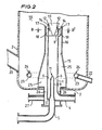
- FIG 2 another embodiment of the apparatus according to the invention is shown which is preferably employed as part of an apparatus for fluid catalytic cracking of hydrocarbonaceous material and which, in addition to the elements already described in connection with Figure 1, comprises solids inlet means (20) through which solid particles (e.g. originating from a catalyst regenerator) are introduced into the bottom section of solids container (2) (which can be the riser reactor of a fluid catalytic cracking apparatus).
- a cooling gas e.g. low pressure steam
- a heavy hydrocarbon oil feed is introduced through inlet means (5) and accellerated through nozzle (11) in the downstream end part (9) thereof into fluid supply means (1) where mixing with steam introduced via inlet means (4) can take place.
- the invention is illustrated by means of the following Example.
- a feed stream of heavy hydrocarbon oil enters inlet (5) of the apparatus as depicted in Figure 2 at a temperature of 250 °C and a pressure of 12 bar abs. and is mixed in tubular fluid supply means (1) having length of 3 m and a diameter of 0.2 m with steam introduced via inlet (4) at a temperature of 300 °C and a pressure of 15 bar abs.
- the resulting oil/steam mixture flows with a velocity of 50 m/s through annular outlet opening (12) into mixing zone (19), which is operated at a pressure of 3 bar abs. and a temperature of 520 °C.
- Regenerated silica-aluminia based catalyst particles are introduces via inlet (20) at a temperature of 700 °C into mixing zone (19) wherein the catalyst particles are contacted with the oil/steam mixture.
Landscapes
- Chemical & Material Sciences (AREA)
- Chemical Kinetics & Catalysis (AREA)
- Engineering & Computer Science (AREA)
- Oil, Petroleum & Natural Gas (AREA)
- Organic Chemistry (AREA)
- General Chemical & Material Sciences (AREA)
- Combustion & Propulsion (AREA)
- Dispersion Chemistry (AREA)
- Production Of Liquid Hydrocarbon Mixture For Refining Petroleum (AREA)
- Devices And Processes Conducted In The Presence Of Fluids And Solid Particles (AREA)
- Feeding, Discharge, Calcimining, Fusing, And Gas-Generation Devices (AREA)
Abstract
Description
- The invention relates to a process and an apparatus for contacting particulate solids with a fluid, especially contacting catalyst particles with a hydrocarbon oil stream in the lower part of a riser reactor of a fluid catalytic cracking (FCC) unit.
- It is known in FCC-technology to contact hydrocarbon oil with cracking catalyst particles by passing said hydrocarbon oil as an outer annular stream in a generally linear direction, imparting a centrifugal energy component to said stream and passing an inner gas stream concentrically with said outer stream through a restricted opening to bring said stream into contact with catalyst particles.
- It would be advantageous, however, to reduce the relatively large pressure drop resulting from (i) the conversion of linear velocity of the hydrocarbon oil stream into a tangential velocity component corresponding to the afore-mentioned centrifugal energy component and (ii) the subsequent passage of said stream together with an at least partly unbroken inner gas stream through a restricted opening.
- It has now been found that optimal mixing of a fluid with particulate solids can be attained with a relatively small pressure drop without requiring a separate inner fluid stream by introducing an annular fluid stream (preferably as a central, symmetrical, hollow-cone jet) directly into a solids stream.
- The invention therefore relates to a process for contacting particulate solids with a fluid which comprises introducing an annular fluid stream into a stream comprising particulate solids.
- The process according to the present invention can be advantageously applied to contact solid cracking catalyst with a hydrocarbons-comprising fluid.
- The present process can be carried out within a very wide temperature range provided, of course, that the fluid(s) applied does not solidify into large particles; preferably it is carried out at a temperature from 0-800 °C and most preferably from 450-550 °C. The contacting process is generally carried out at elevated pressures, although (sub-)atmospheric pressures are not excluded, provided that a sufficient pressure difference is maintained to introduce the annular fluid stream into the solids stream; preferably it is carried out at a pressure from 1-100 bar abs., and most preferably from 2-6 bar abs. in conjunction with a catalytic cracking operation.
- The ratio of mass flows of solids and fluids is preferably from 1-10 and most preferably from 4-8.
- The invention further relates to an apparatus for contacting particulate solids with a fluid which comprises a solids container at least partly surrounding fluid supply means which have an inlet opening in the upstream end part and an annular fluid outlet opening in the downstream end part thereof. Such an apparatus may contain features of an apparatus for mixing fluids as described in British patent application No. 8607699.
- Preferred embodiments of the apparatus according to the invention are described hereinafter using Figures 1-4 in which reference numerals relating to corresponding parts are the same.
- In Figure 1 a longitudinal section of an apparatus for contacting particulate solids with a fluid is shown.
- In Figure 2 a longitudinal section of the bottom part of a fluid catalytic cracking riser reactor is shown.
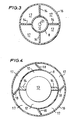
- Figure 3 represents a cross section at AA′ of the fluid supply means of the apparatus as depicted in Figure 1.
- Figure 4 represents a cross section at BB′ of the fluid supply means arranged in the riser reactor section shown in Figure 2.
- The apparatus as schematically depicted in Figure 1 comprises fluid supply means (1) of which the major (downstream) part is surrounded by the bottom part of solids container (2). The upstream end part (3) of fluid supply means (1) preferably comprises separate inlet means (4) for a first fluid and most preferably tubular inlet means (5) for a second fluid arranged partly inside upstream end part (3). In the particularly preferred embodiment as shown in Figure 1 an annular inlet opening (6) for the first fluid is defined between the wall of fluid supply means (1) and tubular inlet means (5) in order to accellerate an upwardly directed stream of the first fluid and to provide an excellent distribution thereof over the cross section of fluid supply means (1). Further accelleration and mixing of the first and second fluid can be attained by employing tubular fluid supply means (1) of which the cross sectional surface area decreases in downstream direction. Preferably, the ratio of the diameters of the upstream (3) - and downstream (8) - end parts of the tubular fluid supply means is from 1-5, and most preferably form 1.2-3.
- A major advantage of the apparatus according to the invention is that a single tubular fluid supply means (1) arranged substantially centrally in the bottom end part (7) of solids container (2) can be applied to attain rapid, intimate and uniform mixing of particulate solids with fluid.
- The downstream end part (9) of tubular inlet means (5) may comprise positioning means, such as outwardly directed spacer fins (10). At least one opening (11) is present in said downstream end part (9); in some cases, however, it can be advantageous to provide downstream end part (9) with a plurality (e.g. 4-12) of openings through which the second fluid will flow with a relatively high velocity (of e.g. 30-300 m/s) and accordingly increase the velocity of the fluid mixture flowing through fluid supply means (1). In a preferred embodiment a deflection means is placed in opening (11), defining an annular fluid opening. The deflection means preferably comprise a rotation-symmetrical body having an increasing diameter in downstream direction.
- The annular fluid outlet opening (12) is preferably defined between the wall of the downstream end part (8) of fluid supply means (1) and deflection means (13), which most preferably comprise a rotation-symmetrical body having an increasing diameter in downstream direction. In a particularly preferred embodiment of the apparatus according to the invention, deflection means (13) comprise a substantially conical body having a top angle of 30-180 degrees and preferably of 80-120 degrees. The ratio of the diameter of the base of said conical body and of the downstream end part (8) of fluid supply means (1) is preferably from 0.8-6 and most preferably from 1-4. Deflection means (13) can be held in place by connecting means (14) which may be arranged either inside or outside (shown in Figure 1) the downstream end part (8) of fluid supply means (1); in the latter case connecting means (14) can also serve as vanes inside annular opening (17) defined between tubular shielding means (16) and the downstream end part (8) of fluid supply means (1). A rod (21) may be arranged substantially coaxially inside fluid supply means (1) and connected to deflection means (13) in order to attain a very stable annular fluid flow around said rod.
- The apparatus according to the present invention furthermore preferably comprises fluidization means (23) (e.g. in the form of a perforated plate as depicted in Figure 1 or ring-shaped or annular fluidization means) provided with regularly spaced fluidization gas openings (e.g. nozzles (24)) through which a fluidization gas (e.g. steam or a sour fluid catalytic cracking off gas) introduced via fluidization gas inlet means (22) emanates into mixing zone (19). Moreover, a separate flow of gas introduced via inlet means (27) may be used to cool space (25) between shielding means (16) and tubular fluid inlet means (1). Solids container (2) may comprise a section having a restricted diameter (not shown in the Figures) near annular fluid outlet opening (17) in order to increase the velocity of the fluidized bed of particulate solids surrounding said opening, thus even further improving the contact between the fluid (mixture) emanating from fluid outlet opening (17) with the solids.
- In Figure 2 another embodiment of the apparatus according to the invention is shown which is preferably employed as part of an apparatus for fluid catalytic cracking of hydrocarbonaceous material and which, in addition to the elements already described in connection with Figure 1, comprises solids inlet means (20) through which solid particles (e.g. originating from a catalyst regenerator) are introduced into the bottom section of solids container (2) (which can be the riser reactor of a fluid catalytic cracking apparatus). A cooling gas (e.g. low pressure steam) can be introduced through cooling gas inlet means (27) and annular cooling gas inlet space (26) into space (25) (enclosed by lower section (15) of shielding means (16)) and be removed through annular opening (17) provided with vanes (18). Preferably, a heavy hydrocarbon oil feed is introduced through inlet means (5) and accellerated through nozzle (11) in the downstream end part (9) thereof into fluid supply means (1) where mixing with steam introduced via inlet means (4) can take place.
- The use of a single fluid/solid contacting apparatus which is centrally located in the bottom section of a riser reactor as depicted in Figure 2 leads to very uniform mixing of solid cracking catalyst and fluid (hydrocarbon/steam mixture) in mixing zone (19) in a relatively short period of time; consequently the length of the riser reactor section in which the solid catalyst particles are mixed with hydrocarbon feed is relatively short, resulting in optimal use of the remaining (upper) section of the riser reactor for the actual catalytic cracking.
- Moreover, by employing the apparatus and process according to the present invention only a relatively small amount of steam or another fluid is used for injecting a given quantity of liquid (hydrocarbons). In addition, coke formation on the catalyst particles and on the walls of the cracking apparatus is reduced as a result of optimal contacting of hydrocarbon feed with said catalyst particles.
- The invention is illustrated by means of the following Example.
- A feed stream of heavy hydrocarbon oil enters inlet (5) of the apparatus as depicted in Figure 2 at a temperature of 250 °C and a pressure of 12 bar abs. and is mixed in tubular fluid supply means (1) having length of 3 m and a diameter of 0.2 m with steam introduced via inlet (4) at a temperature of 300 °C and a pressure of 15 bar abs. The resulting oil/steam mixture flows with a velocity of 50 m/s through annular outlet opening (12) into mixing zone (19), which is operated at a pressure of 3 bar abs. and a temperature of 520 °C. Regenerated silica-aluminia based catalyst particles are introduces via inlet (20) at a temperature of 700 °C into mixing zone (19) wherein the catalyst particles are contacted with the oil/steam mixture.
Claims (14)
Priority Applications (1)
| Application Number | Priority Date | Filing Date | Title |
|---|---|---|---|
| AT87200522T ATE58159T1 (en) | 1986-03-27 | 1987-03-20 | DEVICE FOR CONTACTING SOLID PARTICLES WITH A LIQUID. |
Applications Claiming Priority (2)
| Application Number | Priority Date | Filing Date | Title |
|---|---|---|---|
| GB868607698A GB8607698D0 (en) | 1986-03-27 | 1986-03-27 | Contacting particulate solids with fluid |
| GB8607698 | 1986-03-27 |
Publications (2)
| Publication Number | Publication Date |
|---|---|
| EP0241966A1 true EP0241966A1 (en) | 1987-10-21 |
| EP0241966B1 EP0241966B1 (en) | 1990-11-07 |
Family
ID=10595369
Family Applications (1)
| Application Number | Title | Priority Date | Filing Date |
|---|---|---|---|
| EP87200522A Expired - Lifetime EP0241966B1 (en) | 1986-03-27 | 1987-03-20 | Apparatus for contacting particulate solids with a fluid |
Country Status (19)
| Country | Link |
|---|---|
| US (1) | US4795547A (en) |
| EP (1) | EP0241966B1 (en) |
| JP (1) | JPS62237940A (en) |
| CN (1) | CN1017972B (en) |
| AR (1) | AR242916A1 (en) |
| AT (1) | ATE58159T1 (en) |
| AU (1) | AU594138B2 (en) |
| BR (1) | BR8701392A (en) |
| CA (1) | CA1288931C (en) |
| DE (1) | DE3765977D1 (en) |
| ES (1) | ES2019090B3 (en) |
| GB (1) | GB8607698D0 (en) |
| IN (1) | IN169344B (en) |
| MX (1) | MX170622B (en) |
| MY (1) | MY102297A (en) |
| NL (1) | NL8700705A (en) |
| SG (1) | SG28592G (en) |
| SU (1) | SU1551240A3 (en) |
| ZA (1) | ZA872187B (en) |
Cited By (2)
| Publication number | Priority date | Publication date | Assignee | Title |
|---|---|---|---|---|
| US5160706A (en) * | 1989-10-17 | 1992-11-03 | Shell Oil Company | Process for the catalytic cracking of a hydrocarbon oil |
| EP0593171A1 (en) * | 1992-10-13 | 1994-04-20 | Texaco Development Corporation | Method for atomizing feedstock in a fluid catalytic cracking process |
Families Citing this family (25)
| Publication number | Priority date | Publication date | Assignee | Title |
|---|---|---|---|---|
| US4957617A (en) * | 1986-09-03 | 1990-09-18 | Mobil Oil Corporation | Fluid catalytic cracking |
| CH689284A5 (en) * | 1995-02-16 | 1999-01-29 | Buehler Ag | Shaft reactor with descending bed of granular material, for post |
| US6387247B1 (en) * | 1999-09-03 | 2002-05-14 | Shell Oil Company | Feed injection system for catalytic cracking process |
| DE10260738A1 (en) * | 2002-12-23 | 2004-07-15 | Outokumpu Oyj | Process and plant for conveying fine-grained solids |
| DE10260734B4 (en) * | 2002-12-23 | 2005-05-04 | Outokumpu Oyj | Process and plant for the production of carbon coke |
| DE10260741A1 (en) * | 2002-12-23 | 2004-07-08 | Outokumpu Oyj | Process and plant for the heat treatment of fine-grained solids |
| DE10260733B4 (en) * | 2002-12-23 | 2010-08-12 | Outokumpu Oyj | Process and plant for the heat treatment of iron oxide-containing solids |
| DE10260731B4 (en) | 2002-12-23 | 2005-04-14 | Outokumpu Oyj | Process and plant for the heat treatment of iron oxide-containing solids |
| DE10260737B4 (en) * | 2002-12-23 | 2005-06-30 | Outokumpu Oyj | Process and plant for the heat treatment of titanium-containing solids |
| DE10260739B3 (en) * | 2002-12-23 | 2004-09-16 | Outokumpu Oy | Process and plant for producing metal oxide from metal compounds |
| DE102004042430A1 (en) * | 2004-08-31 | 2006-03-16 | Outokumpu Oyj | Fluidized bed reactor for the thermal treatment of vortex substances in a microwave-heated fluidized bed |
| EP2045002A1 (en) * | 2007-10-02 | 2009-04-08 | Ineos Europe Limited | Mixing apparatus |
| EP2519341B1 (en) * | 2009-12-29 | 2018-01-03 | Indian Oil Corporation Limited | Feed nozzle assembly and process for atomizing a hydrocarbon liquid using said nozzle assembly |
| RU2647311C2 (en) * | 2012-10-25 | 2018-03-15 | Шелл Интернэшнл Рисерч Маатсхаппий Б.В. | Feed nozzle assembly for the catalytic cracking reactor |
| CN103394311B (en) * | 2013-08-08 | 2015-07-01 | 攀钢集团攀枝花钢铁研究院有限公司 | Device and process for liquid-solid fluidized reaction |
| CN109382046B (en) * | 2017-08-11 | 2021-03-09 | 中国石油天然气股份有限公司 | Fixed fluidized bed reactor feeding system |
| CN110961052A (en) * | 2018-09-30 | 2020-04-07 | 中国石油天然气股份有限公司 | Riser catalytic cracking unit |
| CN110961045A (en) * | 2018-09-30 | 2020-04-07 | 中国石油天然气股份有限公司 | Riser catalytic cracking unit |
| CN110961043A (en) * | 2018-09-30 | 2020-04-07 | 中国石油天然气股份有限公司 | Riser catalytic cracking unit |
| CN110961051A (en) * | 2018-09-30 | 2020-04-07 | 中国石油天然气股份有限公司 | Atomizing nozzle for catalytic cracking unit reaction |
| CN110961048A (en) * | 2018-09-30 | 2020-04-07 | 中国石油天然气股份有限公司 | A kind of atomizing nozzle for catalytic cracking unit |
| CN110961049A (en) * | 2018-09-30 | 2020-04-07 | 中国石油天然气股份有限公司 | A riser catalytic cracking device |
| CN110961047A (en) * | 2018-09-30 | 2020-04-07 | 中国石油天然气股份有限公司 | Nozzle for catalytic cracking device |
| CN110961268A (en) * | 2018-09-30 | 2020-04-07 | 中国石油天然气股份有限公司 | A kind of atomizing nozzle for riser |
| JP2022542603A (en) * | 2019-07-30 | 2022-10-05 | シエル・インターナシヨネイル・リサーチ・マーチヤツピイ・ベー・ウイ | riser reactor system |
Citations (5)
| Publication number | Priority date | Publication date | Assignee | Title |
|---|---|---|---|---|
| GB801421A (en) * | 1955-11-14 | 1958-09-10 | Exxon Research Engineering Co | Gas distributor for fluidized reactions |
| US3848811A (en) * | 1973-12-19 | 1974-11-19 | Sun Oil Co Pennsylvania | Device for injecting a fluid into a fluidized bed of particulate material |
| US4414101A (en) * | 1981-08-17 | 1983-11-08 | Standard Oil Company (Indiana) | Hydrocarbon conversion method and apparatus |
| US4563334A (en) * | 1983-12-02 | 1986-01-07 | Phillips Petroleum Company | Catalytic cracking unit |
| EP0180291A1 (en) * | 1984-10-26 | 1986-05-07 | Mobil Oil Corporation | Feed mixing technique for fluidized catalytic cracking of hydrocarbon oil |
Family Cites Families (7)
| Publication number | Priority date | Publication date | Assignee | Title |
|---|---|---|---|---|
| US3071540A (en) * | 1959-10-27 | 1963-01-01 | Kellogg M W Co | Oil feed system for fluid catalytic cracking unit |
| US3152065A (en) * | 1961-09-14 | 1964-10-06 | Exxon Research Engineering Co | Feed injector for cracking of petroleum |
| US4391611A (en) * | 1981-03-05 | 1983-07-05 | The United States Of America As Represented By The United States Department Of Energy | Gasification system |
| US4427537A (en) * | 1982-03-17 | 1984-01-24 | Dean Robert R | Method and means for preparing and dispersing atomed hydrocarbon with fluid catalyst particles in a reactor zone |
| IT1168698B (en) * | 1983-11-21 | 1987-05-20 | Finike Italiana Marposs | HEAD FOR THE CONTROL OF LINEAR DIMENSIONS |
| US4555328A (en) * | 1984-01-19 | 1985-11-26 | Mobil Oil Corporation | Method and apparatus for injecting liquid hydrocarbon feed and steam into a catalytic cracking zone |
| US4687642A (en) * | 1985-01-08 | 1987-08-18 | Phillips Petroleum Company | Fluid feed apparatus |
-
1986
- 1986-03-27 GB GB868607698A patent/GB8607698D0/en active Pending
-
1987
- 1987-03-09 US US07/023,322 patent/US4795547A/en not_active Expired - Fee Related
- 1987-03-20 AT AT87200522T patent/ATE58159T1/en not_active IP Right Cessation
- 1987-03-20 EP EP87200522A patent/EP0241966B1/en not_active Expired - Lifetime
- 1987-03-20 ES ES87200522T patent/ES2019090B3/en not_active Expired - Lifetime
- 1987-03-20 DE DE8787200522T patent/DE3765977D1/en not_active Expired - Lifetime
- 1987-03-23 CA CA000532729A patent/CA1288931C/en not_active Expired - Fee Related
- 1987-03-25 AR AR87307100A patent/AR242916A1/en active
- 1987-03-25 SU SU874202210A patent/SU1551240A3/en active
- 1987-03-25 ZA ZA872187A patent/ZA872187B/en unknown
- 1987-03-25 MX MX005707A patent/MX170622B/en unknown
- 1987-03-25 CN CN87102269A patent/CN1017972B/en not_active Expired
- 1987-03-25 AU AU70631/87A patent/AU594138B2/en not_active Ceased
- 1987-03-25 MY MYPI87000373A patent/MY102297A/en unknown
- 1987-03-25 JP JP62069287A patent/JPS62237940A/en active Pending
- 1987-03-25 IN IN214/MAS/87A patent/IN169344B/en unknown
- 1987-03-26 NL NL8700705A patent/NL8700705A/en not_active Application Discontinuation
- 1987-03-26 BR BR8701392A patent/BR8701392A/en not_active IP Right Cessation
-
1992
- 1992-03-09 SG SG285/92A patent/SG28592G/en unknown
Patent Citations (5)
| Publication number | Priority date | Publication date | Assignee | Title |
|---|---|---|---|---|
| GB801421A (en) * | 1955-11-14 | 1958-09-10 | Exxon Research Engineering Co | Gas distributor for fluidized reactions |
| US3848811A (en) * | 1973-12-19 | 1974-11-19 | Sun Oil Co Pennsylvania | Device for injecting a fluid into a fluidized bed of particulate material |
| US4414101A (en) * | 1981-08-17 | 1983-11-08 | Standard Oil Company (Indiana) | Hydrocarbon conversion method and apparatus |
| US4563334A (en) * | 1983-12-02 | 1986-01-07 | Phillips Petroleum Company | Catalytic cracking unit |
| EP0180291A1 (en) * | 1984-10-26 | 1986-05-07 | Mobil Oil Corporation | Feed mixing technique for fluidized catalytic cracking of hydrocarbon oil |
Cited By (2)
| Publication number | Priority date | Publication date | Assignee | Title |
|---|---|---|---|---|
| US5160706A (en) * | 1989-10-17 | 1992-11-03 | Shell Oil Company | Process for the catalytic cracking of a hydrocarbon oil |
| EP0593171A1 (en) * | 1992-10-13 | 1994-04-20 | Texaco Development Corporation | Method for atomizing feedstock in a fluid catalytic cracking process |
Also Published As
| Publication number | Publication date |
|---|---|
| US4795547A (en) | 1989-01-03 |
| AU594138B2 (en) | 1990-03-01 |
| CN1017972B (en) | 1992-08-26 |
| NL8700705A (en) | 1987-10-16 |
| DE3765977D1 (en) | 1990-12-13 |
| BR8701392A (en) | 1988-01-05 |
| SG28592G (en) | 1992-06-12 |
| JPS62237940A (en) | 1987-10-17 |
| ATE58159T1 (en) | 1990-11-15 |
| AR242916A1 (en) | 1993-06-30 |
| MX170622B (en) | 1993-08-31 |
| CA1288931C (en) | 1991-09-17 |
| AU7063187A (en) | 1987-10-01 |
| IN169344B (en) | 1991-09-28 |
| EP0241966B1 (en) | 1990-11-07 |
| SU1551240A3 (en) | 1990-03-15 |
| GB8607698D0 (en) | 1986-04-30 |
| MY102297A (en) | 1992-05-28 |
| ES2019090B3 (en) | 1991-06-01 |
| ZA872187B (en) | 1987-09-16 |
| CN87102269A (en) | 1987-11-25 |
Similar Documents
| Publication | Publication Date | Title |
|---|---|---|
| EP0241966A1 (en) | Apparatus for contacting particulate solids with a fluid | |
| EP0848051B1 (en) | Fluid catalytic cracking of hydrocarbons with integrated apparatus for separating and stripping catalyst | |
| CA1305436C (en) | Apparatus and process for solids-fluid separation | |
| US2358497A (en) | Method of conducting conversion reactions | |
| US5205992A (en) | Apparatus for introducing catalyst particles into a moving bed of catalyst | |
| EP0239171B1 (en) | Apparatus and process for mixing fluids | |
| US4784328A (en) | Nozzle assembly | |
| US4681743A (en) | Catalytic cracking apparatus | |
| US5552119A (en) | Method and apparatus for contacting solid particles and fluid | |
| US4675099A (en) | Flowing catalyst particles in annular stream around a plug in lift pot | |
| US4824557A (en) | Process for mixing cracking catalyst with a fluid hydrocarbon | |
| US3475326A (en) | Transfer line apparatus and method | |
| US7060228B2 (en) | Internal device for separating a mixture that comprises at least one gaseous phase and one liquid phase | |
| US4808382A (en) | Process for mixing cracking catalyst with a fluid hydrocarbon | |
| US4711766A (en) | Apparatus for mixing cracking catalyst with a fluid hydrocarbon | |
| US5160706A (en) | Process for the catalytic cracking of a hydrocarbon oil | |
| US2461172A (en) | Pyrolytic conversion of hydrocarbons | |
| JPH03140395A (en) | Catalytic cracking method for hydrocarbon oil | |
| US4624836A (en) | Apparatus and process for mixing cracking catalyst with a fluid hydrocarbon | |
| EP0952202A1 (en) | Fluid catalytic cracking reactor system |
Legal Events
| Date | Code | Title | Description |
|---|---|---|---|
| PUAI | Public reference made under article 153(3) epc to a published international application that has entered the european phase |
Free format text: ORIGINAL CODE: 0009012 |
|
| AK | Designated contracting states |
Kind code of ref document: A1 Designated state(s): AT BE CH DE ES FR GB IT LI SE |
|
| 17P | Request for examination filed |
Effective date: 19880211 |
|
| 17Q | First examination report despatched |
Effective date: 19880919 |
|
| GRAA | (expected) grant |
Free format text: ORIGINAL CODE: 0009210 |
|
| AK | Designated contracting states |
Kind code of ref document: B1 Designated state(s): AT BE CH DE ES FR GB IT LI SE |
|
| REF | Corresponds to: |
Ref document number: 58159 Country of ref document: AT Date of ref document: 19901115 Kind code of ref document: T |
|
| ITF | It: translation for a ep patent filed | ||
| REF | Corresponds to: |
Ref document number: 3765977 Country of ref document: DE Date of ref document: 19901213 |
|
| ET | Fr: translation filed | ||
| ITTA | It: last paid annual fee | ||
| PLBE | No opposition filed within time limit |
Free format text: ORIGINAL CODE: 0009261 |
|
| STAA | Information on the status of an ep patent application or granted ep patent |
Free format text: STATUS: NO OPPOSITION FILED WITHIN TIME LIMIT |
|
| 26N | No opposition filed | ||
| EAL | Se: european patent in force in sweden |
Ref document number: 87200522.8 |
|
| PGFP | Annual fee paid to national office [announced via postgrant information from national office to epo] |
Ref country code: FR Payment date: 19970124 Year of fee payment: 11 |
|
| PGFP | Annual fee paid to national office [announced via postgrant information from national office to epo] |
Ref country code: SE Payment date: 19970206 Year of fee payment: 11 |
|
| PGFP | Annual fee paid to national office [announced via postgrant information from national office to epo] |
Ref country code: GB Payment date: 19970211 Year of fee payment: 11 |
|
| PGFP | Annual fee paid to national office [announced via postgrant information from national office to epo] |
Ref country code: AT Payment date: 19970220 Year of fee payment: 11 |
|
| PGFP | Annual fee paid to national office [announced via postgrant information from national office to epo] |
Ref country code: BE Payment date: 19970305 Year of fee payment: 11 |
|
| PGFP | Annual fee paid to national office [announced via postgrant information from national office to epo] |
Ref country code: ES Payment date: 19970321 Year of fee payment: 11 |
|
| PGFP | Annual fee paid to national office [announced via postgrant information from national office to epo] |
Ref country code: DE Payment date: 19970408 Year of fee payment: 11 |
|
| PGFP | Annual fee paid to national office [announced via postgrant information from national office to epo] |
Ref country code: CH Payment date: 19970602 Year of fee payment: 11 |
|
| PG25 | Lapsed in a contracting state [announced via postgrant information from national office to epo] |
Ref country code: GB Free format text: LAPSE BECAUSE OF NON-PAYMENT OF DUE FEES Effective date: 19980320 Ref country code: AT Free format text: LAPSE BECAUSE OF NON-PAYMENT OF DUE FEES Effective date: 19980320 |
|
| PG25 | Lapsed in a contracting state [announced via postgrant information from national office to epo] |
Ref country code: SE Free format text: LAPSE BECAUSE OF NON-PAYMENT OF DUE FEES Effective date: 19980321 Ref country code: ES Free format text: LAPSE BECAUSE OF EXPIRATION OF PROTECTION Effective date: 19980321 |
|
| PG25 | Lapsed in a contracting state [announced via postgrant information from national office to epo] |
Ref country code: LI Free format text: LAPSE BECAUSE OF NON-PAYMENT OF DUE FEES Effective date: 19980331 Ref country code: FR Free format text: THE PATENT HAS BEEN ANNULLED BY A DECISION OF A NATIONAL AUTHORITY Effective date: 19980331 Ref country code: CH Free format text: LAPSE BECAUSE OF NON-PAYMENT OF DUE FEES Effective date: 19980331 Ref country code: BE Free format text: LAPSE BECAUSE OF NON-PAYMENT OF DUE FEES Effective date: 19980331 |
|
| BERE | Be: lapsed |
Owner name: SHELL INTERNATIONALE RESEARCH MAATSCHAPPIJ B.V. Effective date: 19980331 |
|
| GBPC | Gb: european patent ceased through non-payment of renewal fee |
Effective date: 19980320 |
|
| REG | Reference to a national code |
Ref country code: CH Ref legal event code: PL |
|
| PG25 | Lapsed in a contracting state [announced via postgrant information from national office to epo] |
Ref country code: DE Free format text: LAPSE BECAUSE OF NON-PAYMENT OF DUE FEES Effective date: 19981201 |
|
| EUG | Se: european patent has lapsed |
Ref document number: 87200522.8 |
|
| REG | Reference to a national code |
Ref country code: FR Ref legal event code: ST |
|
| REG | Reference to a national code |
Ref country code: ES Ref legal event code: FD2A Effective date: 20000201 |
|
| PG25 | Lapsed in a contracting state [announced via postgrant information from national office to epo] |
Ref country code: IT Free format text: LAPSE BECAUSE OF NON-PAYMENT OF DUE FEES;WARNING: LAPSES OF ITALIAN PATENTS WITH EFFECTIVE DATE BEFORE 2007 MAY HAVE OCCURRED AT ANY TIME BEFORE 2007. THE CORRECT EFFECTIVE DATE MAY BE DIFFERENT FROM THE ONE RECORDED. Effective date: 20050320 |