EP0241698B1 - Pipe with replaceable cartridge - Google Patents
Pipe with replaceable cartridge Download PDFInfo
- Publication number
- EP0241698B1 EP0241698B1 EP87103278A EP87103278A EP0241698B1 EP 0241698 B1 EP0241698 B1 EP 0241698B1 EP 87103278 A EP87103278 A EP 87103278A EP 87103278 A EP87103278 A EP 87103278A EP 0241698 B1 EP0241698 B1 EP 0241698B1
- Authority
- EP
- European Patent Office
- Prior art keywords
- pipe
- aerosol
- cartridge
- fuel element
- fuel
- Prior art date
- Legal status (The legal status is an assumption and is not a legal conclusion. Google has not performed a legal analysis and makes no representation as to the accuracy of the status listed.)
- Expired - Lifetime
Links
Images
Classifications
-
- A—HUMAN NECESSITIES
- A24—TOBACCO; CIGARS; CIGARETTES; SIMULATED SMOKING DEVICES; SMOKERS' REQUISITES
- A24D—CIGARS; CIGARETTES; TOBACCO SMOKE FILTERS; MOUTHPIECES OF CIGARS OR CIGARETTES; MANUFACTURE OF TOBACCO SMOKE FILTERS OR MOUTHPIECES
- A24D1/00—Cigars; Cigarettes
- A24D1/14—Tobacco cartridges for pipes
-
- A—HUMAN NECESSITIES
- A24—TOBACCO; CIGARS; CIGARETTES; SIMULATED SMOKING DEVICES; SMOKERS' REQUISITES
- A24D—CIGARS; CIGARETTES; TOBACCO SMOKE FILTERS; MOUTHPIECES OF CIGARS OR CIGARETTES; MANUFACTURE OF TOBACCO SMOKE FILTERS OR MOUTHPIECES
- A24D1/00—Cigars; Cigarettes
- A24D1/20—Cigarettes specially adapted for simulated smoking devices
-
- A—HUMAN NECESSITIES
- A24—TOBACCO; CIGARS; CIGARETTES; SIMULATED SMOKING DEVICES; SMOKERS' REQUISITES
- A24D—CIGARS; CIGARETTES; TOBACCO SMOKE FILTERS; MOUTHPIECES OF CIGARS OR CIGARETTES; MANUFACTURE OF TOBACCO SMOKE FILTERS OR MOUTHPIECES
- A24D1/00—Cigars; Cigarettes
- A24D1/22—Cigarettes with integrated combustible heat sources, e.g. with carbonaceous heat sources
-
- A—HUMAN NECESSITIES
- A24—TOBACCO; CIGARS; CIGARETTES; SIMULATED SMOKING DEVICES; SMOKERS' REQUISITES
- A24F—SMOKERS' REQUISITES; MATCH BOXES; SIMULATED SMOKING DEVICES
- A24F1/00—Tobacco pipes
-
- A—HUMAN NECESSITIES
- A24—TOBACCO; CIGARS; CIGARETTES; SIMULATED SMOKING DEVICES; SMOKERS' REQUISITES
- A24F—SMOKERS' REQUISITES; MATCH BOXES; SIMULATED SMOKING DEVICES
- A24F42/00—Simulated smoking devices other than electrically operated; Component parts thereof; Manufacture or testing thereof
- A24F42/10—Devices with chemical heating means
-
- A—HUMAN NECESSITIES
- A24—TOBACCO; CIGARS; CIGARETTES; SIMULATED SMOKING DEVICES; SMOKERS' REQUISITES
- A24F—SMOKERS' REQUISITES; MATCH BOXES; SIMULATED SMOKING DEVICES
- A24F42/00—Simulated smoking devices other than electrically operated; Component parts thereof; Manufacture or testing thereof
- A24F42/60—Constructional details
Definitions
- the present invention relates to a pipe comprising a bowl, a replaceable insert adapted for comprising a fuel and being provided with a physically separate aerosol generating means including at least one aerosol forming material which, when being in use, is in a conductive heat exchange relationship with the fuel, as well as means for retaining the insert in the bowl, said retaining means being adapted to permit removal and replacement of the insert.
- a pipe of this type is disclosed in US-A- 4,474,191 (Steiner).
- This known pipe has a cupule like insert to be filled by the smoker with a charge of cut tobacco or another combustible material providing the fuel of this known pipe.
- the cupule like insert has a hole which is closed during normal smoking.
- the pipe contains an air-intake channel a section of which is defined by an annular chamber between the bowl and the circumferential wall of the cupule like insert the outer side of which is impregnated with substances forming an aerosol when the wall is heated by the burning fuel; this air-intake channel is in communication with the passageway of the stem of the pipe.
- To assist in the lighting of this known pipe means are provided for allowing a brief, temporary passage of gases between the combustion chamber provided by the cupule like insert and the passageway of the stem of the pipe.
- a pipe of the type defined at the beginning which, according to the invention, has an insert in the form of a cartridge containing the aerosol forming material and comprising a fuel element less than about 30 mm in length.
- the aerosol forming material is contained in the cartridge which also comprises a short fuel element the fire cone of the fuel element is always in close proximity to the aerosol generating means even though by providing a fuel being physically separate from the aerosol forming material the possibility of thermal degradation of the aerosol forming material is minimized thereby also eliminating the presence of substantial pyrolysis or incomplete combustion products and avoiding the production of sidestream smoke.
- the fire cone of the fuel element of the inventive cartridge is always in close proximity to the aerosol forming material there is never a long section of non-burning fuel to act as a heat sink so that the inventive combination results in high heat delivery both during puffing of the pipe and during the relatively long period of smolder between the puffs.
- the inventive cartridge with its short fuel element and with the aerosol forming material contained in the cartridge, is small and compact and easy to replace.
- the fuel element is carbonaceous, and in preferred embodiments the cartridge does not extend above the rim of the pipe bowl.
- the use of the inventive cartridge avoids the multiple step recharging problems of prior art pipe-type smoking articles such as those known from US-A-4,474,191.
- the retaining means of the pipe of the present invention may comprise a removable member having a hole adapted to receive one end of the cartridge which also is aligned with the passageway through stem, such that aerosol forming materials may freely pas from the cartridge to the stem passageway and be delivered to the user as a smoke-like aerosol.
- the retaining means for the pipe of the present invention incorporates an ejection means by which spent cartridges may be easily removed form the pipe bowl.
- the aerosol generating means and the fuel element of the cartridge are in a conductive heat exchange relationship, and/or the aerosol forming substance is located within a heat conductive container provided with passages through which gases and vapors may pass into the pipe stem and be delivered to the user akin to conventional pipe tobacco smoke.
- the fuel elements used in the cartridge are preferably less than about 20 mm in length, more preferably less than about 15 mm in length, and have a density of at least about 0.5 g/cc, preferably at least about 0.7 g/cc, as measured by mercury intrusion.
- Preferred fuel element are normally provided with one or more longitudinal passageways, preferably from 5 to 9 passageways, which help to control the transfert of heat from the fuel element to the aerosol forming substance.
- the heat exchange relationship between the fuel and the aerosol generator is preferably achieved by providing a heat conducting member, such as a metal conductor, which contacts the fuel element and at least a portion of the aerosol generating means, and preferably forms the conductive container for the aerosol forming materials.
- a heat conducting member such as a metal conductor
- Preferred cartridges of the type described herein are particularly advantageous because the hot, burning fire cone is always close to the aerosol generating means, which maximizes heat transfert thereto and maximizes the resultant production of aerosol, especially in embodiments which are provided with a multiple passageway fuel element and a heat conducting member.
- the aerosol forming substance is physically separate from the fuel element, it is exposed to substantially lower temperatures than are present in the burning fire cone, thereby minimizing to possibility of thermal degradation of the aerosol former.
- the aerosol generating means may include a charge of tobacco to add additional tobacco flavors to the aerosol.
- this tobacco charge may be placed at the stem end of the cartridge and/or it may be mixed with a carrier for the aerosol forming substance.
- Other substances, such as flavoring agents, may be incorporated in a similar manner.
- a tobacco charge may be used as the carrier for the aerosol forming substance.
- tobacco or a tobacco extract flavor may alternatively, or additionally, be incorporated in the fuel element to provide additional tobacco flavor.
- preferred pipes of the present invention are capable of providing an aerosol which is chemically simple, consisting essentially of air, oxides of carbon, water, the aerosol former, any desired flavors or other desired volatile materials, and trace amounts of other materials.
- This aerosol has no significant mutagenic activity as measured by the Ames Test.
- aerosol is defined to include vapors, gases, particles, and the like, both visible and invisible, and especially those components perceived by the user to be “smoke-like", generated by action of the heat from the burning fuel element upon substances contained within the aerosol generating means, or elsewhere in the article.
- aerosol also includes volatile flavoring agents and/or pharmacologically or physiologically active agents, irrespective of whether they produce a visible aerosol.
- conductive heat exchange relationship is defined as a physical arrangement of the aerosol generating means and the fuel element whereby heat is transferred by conduction from the burning fuel element to the aerosol generating means substantially throughout the burning period of the fuel element.
- Conductive heat exchange relationships can be achieved by placing the aerosol generating means in contact with the fuel element and thus in close proximity to the burning portion of the fuel element, and/or by utilizing a conductive member to carry heat from the burning fuel to the aerosol generating means. Preferably both methods of providing conductive heat transfer are used.
- carbonaceous means primarily comprising carbon
- Figure 1 is a perspective view of a pipe according to the present invention having a portion of the bowl and stem removed, showing the cartridge and the bowl conversion member.
- Figure 2 is a sectional view of the bowl/stem arrangement of the pipe of Figure 1, illustrating the placement of the cartridge and the bowle conversion member of the present invention.
- Figure 3 is a sectional view of another pipe of the present invention, having its bowl modified to directly accept the cartridge of the present invention and illustrating one cartridge ejection means.
- Figure 4 is a top view of the pipe of Figure 3, illustrating the relative size of the preferred fuel element to the bowl and one preferred arrangement of fuel element passageways.
- the embodiment of the invention illustrated in Figures 1 and 2 has about the same overall dimensions as a conventional pipe. It includes a conventional pipe 10 comprising a bowl 12, a stem 14, an annular bowl conversion member 16, and a replaceable cartridge 18.
- the cartridge 18 includes a short, combustible carbonaceous fuel element 20 inserted into a heat conductive container 22, which container encloses a substrate 24 bearing at least one aerosol forming substance.
- Cartridge 18 fits into bowl conversion member 16 making the cartridge useful in any conventional pipe.
- the carbonaceous fuel element 20 is about 10 mm long and about 4.5 mm in diameter, and is provided with seven passageways 26, as illustrated in Figure 4.
- the heat conductive container 22, is a metal, e.g., aluminum, tube about 30 mm long and about 4.5 mm in diameter.
- the substrate 24 may be, for example about 200 mg of granular alumina, bearing one or more aerosol forming substances such as glycerin, tobacco extracts, and/or flavors.
- the bottom end of the container is sealed to retain the substrate but includes at least one opening 27 to allow the passage of aerosol forming gases to the passageway 28 in the stem 14.
- the fuel element 20 extends about 7 mm beyond the open end of the container 22.
- the bowl conversion member 16 is generally an annular member designed to receive up to about 5 mm of the bottom portion of the cartridge 16.
- the conversion member 16 is also designed to fit snugly into the bottom of the pipe bowl 12.
- the hole in the annular member 16 is preferably aligned with the opening to passageway 28 in the stem 14 of the pipe.
- the cartridge does not extend beyond the rim of the pipe bowl.
- the distance from the top of the fuel element in the cartridge and the rim of the pipe bowl is at least about 1 mm, preferably about 3 mm or more. This recessed cartridge decreases the possibility that careless handling will cause a fire or burn the user.
- the pipe bowl 12 may be shaped to accept the cartridge 18 and may include a cartridge ejection means 30.
- one such ejection means comprises an elongated member 32, slidably mounted through the bottom of the pipe bowl 12, to engage the bottom of the cartridge 18.
- the elongated member 32 is designed so as not to obstruct the passageway 28 of stem 14 and may include an enlarged knob 34.
- the fuel element Upon lighting, the fuel element burns, generating the heat used to volatilize the aerosol forming substance or substances in the aerosol generating means. Because the preferred fuel element is relatively short, the hot, burning fire cone is always close to the aerosol generating means, which maximizes heat transfert to the aerosol generating means and resultant production of aeroso, especially when the preferred heat conducting member is used.
- the small size and burning characteristics of the preferred fuel elements employed in the present invention ensure that the fuel element will begin to burn over substantially all of its exposed length within a few puffs. Thus, that portion of the fuel element adjacent to the aerosol generator becomes hot quickly, which significantly increases heat transfer to the aerosol generator, especially during the early and middle puffs. Control of heat transfer to the aerosol generating means is important both in terms of transferring enough heat to produce sufficient aerosol and in terms of avoiding the transfert of so much heat that the aerosol former is degraded. Heat transfer is enhanced by the heat conductive material employed in the preferred conductive container for the aerosol forming substances, which aids in the distribution of heat to that portion of the aerosol forming substance which is physically remote from the fuel.
- the control of heat transfer form the fuel element to the aerosol generating means is also aided by the presence of a plurality of passageways in the fuel element, which allow the rapid passage of hot gases to the aerosol generator, especially during puffing.
- the aerosol forming substance is physically separate from the fuel element, the aerosol forming substance is exposed to substantially lower temperatures than are generated by the burning fuel, thereby minimizing the possibility of its thermal degradation. This also results in aerosol production almost exclusively during puffing, with little or no aerosol production from the aerosol generating means during smolder.
- the short carbonaceous fuel element and the aerosol generator cooperate to provide a system which is capable of producing substantial quantities of aerosol, on virtually every puff.
- the combustible fuel elements which may be employed in the cartridges of the present invention have a diameter of at least about 2 mm, preferably from about 4 mm to 8 mm, and are generally less than about 30 mm long.
- the fuel element is about 20 mm or less in length, preferably about 15 mm or less in length.
- the density of the fuel elements employed herein may range from about 0.5 g/cc to about 1.5 g/cc, as measured by mercury porosity.
- the density is greater that about 0.7 g/cc, more preferably greater than about 0.8 g/cc.
- the preferred fuel elements employed herein are primarily formed of a carbonaceous material.
- Carbonaceous fuel elements are preferably from about 5 to 15 mm, more preferably, from about 8 to 12 mm in length.
- the carbon content of these fuel elements is at least 60 to 70%, most preferably about 80% or more, by weight.
- High carbon content fuel elements are preferred because they produce minimal pyrolysis and incomplete combustion products, little or no visible sidestream smoke, and minimal ash, and have high heat capacity.
- lower carbon content fuel elements e.g., about 50 to 60% carbon by weight, are within the scope of this invention, especially where a minor amount of tobacco, tobacco extract, or a nonburning inert filler is used.
- other fuel materials may be employed in the cartridge, such as tobacco, tobacco substitutes and the like, provided that they generate and conduct sufficient heat to the aerosol generating means to produce the desired level of aerosol from the aerosol forming material, as discussed above.
- other materials it is much preferred to include carbon in the fuel, preferably in amounts of at least about 20% to 40% by weight, more preferably at least about 50% by weight, and most preferably at least about 65% to 70% by weight, the balance being the other fuel components, including any binder, burn modifiers, moisture, etc.
- the carbonaceous materials used in or as the preferred fuel element may be derived from virtually any of the numerous carbon sources known to those skilled in the art.
- the carbonaceous material is obtained by the pyrolysis or carbonization of cellulosic materials, such as wood, cotton, rayon, tobacco, coconut, paper, and the like, although carbonaceous materials from other sources may be used.
- the carbonaceous fuel elements should be capable of being ignited by a conventional cigarette lighter without the use of an oxidizing agent.
- Burning characteristics of this type may generally be obtained from a cellulosic material which has been pyrolyzed at temperatures between about 400°C to about 1000°C, preferably between about 500°C to about 950°C, most preferably at about 750°C, in an inert atmosphere or under a vacuum.
- the pyrolysis time is not believed to be critical, as long as the temperature at the center of the pyrolyzed mass has reached the aforesaid temperature range for at least a few, e.g., about 15, minutes.
- a slow pyrolysis employing gradually increasing temperatures over many hours, is believed to produce a uniform material with a high carbon yield.
- the pyrolyzed material is then cooled, ground to a fine powder, and heated in an inert gas stream at a temperature between about 650°C to 850°C to remover volatiles prior to further processing.
- the carbonaceous fuel elements are substantially free of volatile organic material.
- the fuel element is not purposely impregnated or mixed with substantial amounts of volatile organic materials, such as volatile aerosol forming or flavoring agents, which could degrade in the burning fuel.
- volatile organic materials such as volatile aerosol forming or flavoring agents, which could degrade in the burning fuel.
- small amounts of materials e.g., water, which are naturally adsorbed by the carbon in the fuel element, may be present therein.
- small amounts of aerosol forming substances may migrate from the aerosol generating means and thus may also be present in the fuel.
- the fuel element may contain minor amounts of tobacco, tobacco extracts, and/or other materials, primarily to add flavor to the aerosol. Amounts of these additives may range up to about 25 weight percent or more, depending upon the additive, the fuel element, and the desired burning characteristics. Tobacco and/or tobacco extracts may be added to carbonaceous fuel elements at about 10 to 20 weight percent, thereby providing tobacco flavors to the mainstream and tobacco aroma to the sidestream akin to a conventional cigarette, without affecting the Ames test activity of the product.
- a preferred carbonaceous fuel element is a pressed or extruded mass of carbon prepared from a powdered carbon and a binder, by pressure forming or extrusion techniques.
- a preferred activated carbon for such a fuel element is PCB-G
- a preferred non-activated carbon is PXC, both available from Calgon Carbon Corporation, Pittsburgh, PA.
- Other preferrednonactivated carbons for pressure forming are prepared from pyrolyzed cotton or pyrolyzed papers, such as non-talc containing grades of Grande Prairie Canadian Kraft, available from the Buckeye Cellulose Corporation of Memphis, TN.
- binders which may be used in preparing such a fuel element are well known in the art.
- a preferred binder is sodium carboxymethylcellulose (SCMC), which may be used alone, which is preferred, or in conjunction with materials such as sodium chloride, vermiculite, bentonite, calcium carbonate, and the like.
- SCMC sodium carboxymethylcellulose
- Other useful binders include gums, such as guar gum, and other cellulose derivatives, such as methylcellulose and carboxymethylcellulose (CMC).
- binder concentrations can be utilized.
- the amount of binder is limited to minimize contribution of the binder to undesirable combustion products.
- sufficient binder must be included to hold the fuel element together during manufacture and use. The amount used will thus depend on the cohesiveness of the carbon in the fuel.
- an extruded carbonaceous fuel may be prepared by admixing from about 50 to 99 weight percent, preferably about 80 to 95 weight percent, of the carbonaceous material, with from 1 to 50 weight percent, preferably about 5 to 20 weight percent of the binder, with sufficient water to make a paste having a stiff dough-like consistency. Minor amounts, e.g., up to about 35 weight percent, preferably about 10 to 20 weight percent, of tobacco, tobacco extract, and the like, may be added to the paste with additional water, if necessary, to maintain a stiff dough consistency. The dough is then formed, e.g., by using a standard ram or piston type extruder into the desired shape, and dried, preferably at about 95°C to reduce the moisture content to about 2 to 7 percent by weight.
- Carbonaceous fuel elements are preferably provided with one or more longitudinally extending passageways. These passageways help to control transfer of heat from the fuel element to the aerosol generating means, which is important both in terms of transferring enough heat to produce sufficient aerosol and in terms of avoiding the transfer of so much heat that the aerosol former is degraded. Generally, these passageways provide porosity and increase early heat transfer to the substrate by increasing the amount of hot gases which reach the substrate. They also tend to increase the rate of burning.
- passageways may be formed during the extrusion step. Alternatively, or additionally, the passageways may be formed using conventional drilling techniques. Generally, a large number of passageways, e.g., about 5 to 9 or more, especially with relatively wide spacings between the passageways, such as the configuration illustrated in Figure 4 is preferred. If desired, the lighting end of the fuel elements may be tapered or reduced in diameter by machining, molding, or the like, to improve lightability.
- a high quality fuel element may be formed by casting a thin slurry of the carbon/binder mixture (with or without additional components) into a sheet, drying the sheet, regarding the dried sheet into a powder, forming a stiff paste with water, and extruding the paste as described above.
- carbon/binder fuel elements may be pyrolyzed after formation, for example, to about 650°C for two hours, to convert the binder to carbon and thereby form a virtually 100% carbon fuel element.
- the fuel elements of the present invention also may contain one or more additives to improve burning, such as up to about 5 weight percent of sodium chloride to improve smoldering characteristics and as a glow retardant.
- weight percent of potassium carbonate may be included to control flammability.
- Additives to improve physical characteristics such as clays like kaolins, serpentines, attapulgites and the like also may be used.
- the aerosol generating means used in the cartridge of the present invention is physically separate from the fuel element.
- physically separate it is meant that the substrate, container, or chamber which contains the aerosol forming materials is not mixed with, or a part of, the fuel element. This arrangement helps reduce or eliminate thermal degradation of the aerosol forming substance and the presence of sidestream smoke.
- the aerosol generating means While not a part of the fuel element, the aerosol generating means generally abuts or is connected to the fuel element such that the fuel element and the aerosol generating means are in a conductive heat exchange relationship.
- the conductive heat exchange relationship is achieved by providing a heat conductive member, such as a metal foil, recessed from the lighting end of the fuel element, which efficiently conducts or transfers heat from the burning fuel element to the aerosol generating means.
- the preferred container for the aerosol generating means may vary in length from about 5 mm to about 40 mm, preferably from about 15 mm to 35 mm, and most preferably from about 20 mm to 30 mm.
- the diameter of the aerosol generating means should be at least about 2 mm, and preferably from about 4 mm to 8 mm.
- the aerosol generating means includes one or more thermally stable materials which carry one or more aerosol forming substances.
- a "thermally stable" material is one capable of withstanding the high, albeit controlled, temperatures, e.g., from about 400°C to about 600°C, which may eventually exist near the fuel, without significant decomposition or burning. The use of such material is believed to help maintain the simple "smoke" chemistry of the aerosol, as evidenced by a lack of Ames test activity in the preferred embodiments.
- other aerosol generating means such as heat rupturable microcapsules, or solid aerosol forming substances, are within the scope of this invention, provided they are capable of releasing sufficient aerosol forming vapors to satisfactorily resemble tobacco smoke.
- Thermally stable materials which may be used as the carrier or substrate for the aerosol forming substance are well known to those skilled in the art.
- Useful carriers should be porous, and must be capable of retaining an aerosol forming compound and releasing a potential aerosol forming vapor upon heating by the fuel.
- Useful thermally stable materials include adsorbent carbons, such as porous grade carbons, graphite, activated, or non-activated carbons, and the like, such as PC-25 and PG-60 available from Union Carbide Corp., Danbury, CT, as well as SGL carbon, available from Calgon.
- Other suitable materials include inorganic solids, such as ceramics, glass, alumina, vermiculite, clays such as bentonite, and the like. Carbon and alumina substrates are preferred.
- alumina substrate is available from the Davison Chemical Division of W.R. Grace & Co. under the designation SMR-14-1896. Before use, this alumina is sintered at elevated temperatures, e.g., greater than 1000°C, washed, and dried.
- suitable particulate substrates also may be formed from carbon, tobacco, or mixtures of carbon and tobacco, into densified particles in a one-step process using a machine made by Fuji Paudal KK of Japan, and sold under the trade name of "Marumerizer.”
- This apparatus is described in German Patent No. 1,294,351 and U.S. Patent No. 3,277,520 (now reissued as No. 27,214) as well as Japanese published specification No. 8684/1967.
- the aerosol forming substance or substances used in the cartridges of the present invention must be capable of forming an aerosol at the temperatures present in the aerosol generating means upon heating by the burning fuel element.
- Such substances preferably will be composed of carbon, hydrogen and oxygen, but they may include other materials.
- Such substances can be in solid, semisolid, or liquid form.
- the boiling or sublimation point of the substance and/or the mixture of substances can range up to about 500°C.
- Substances having these characteristics include: polyhydric alcohols, such as glycerin, triethylene glycol, and propylene glycol, as well as aliphatic esters of mono-, di-, or poly-carboxylic acids, such as methyl stearate, dodecandioate, dimethyl tetradodecandioate, and others.
- polyhydric alcohols such as glycerin, triethylene glycol, and propylene glycol
- aliphatic esters of mono-, di-, or poly-carboxylic acids such as methyl stearate, dodecandioate, dimethyl tetradodecandioate, and others.
- the preferred aerosol forming substances are polyhydric alcohols, or mixtures of polyhydric alcohols. More preferred aerosol formers are selected from glycerine, triethylene glycol and propylene glycol.
- the aerosol forming substance may be dispersed on or within the substrate in a concentration sufficient to permeate or coat the material, by any known technique.
- the aerosol forming substance may be applied full strength or in a dilute solution by dipping, spraying, vapor deposition, or similar techniques.
- Solid aerosol forming components may be admixed with the substrate material and distributed evenly throughout prior to formation of the final substrate.
- the amount of liquid aerosol forming substances may generally vary from about 20 mg to about 120 mg, preferably from about 35 mg to about 85 mg, and most preferably from about 45 mg to about 65 mg.
- the aerosol former carried on the substrate should be delivered to the user as WTPM.
- WTPM weight percent
- the aerosol former carried on the substrate is delivered to the user as WTPM.
- the aerosol generating means also may include one or more volatile flavoring agents, such as menthol, vanillin, artificial coffee, tobacco extracts, nicotine, caffeine, liquors, and other agents which impart flavor to the aerosol. It also may include any other desirable volatile solid or liquid materials.
- volatile flavoring agents such as menthol, vanillin, artificial coffee, tobacco extracts, nicotine, caffeine, liquors, and other agents which impart flavor to the aerosol. It also may include any other desirable volatile solid or liquid materials.
- One particularly preferred aerosol generating means comprises the aforesaid alumina substrate containing spray dried tobacco extract, tobacco flavor modifiers, such as levulinic acid, one or more flavoring agents, and an aerosol forming agent, such as glycerin.
- this substrate may be mixed with densified tobacco particles, such as those produced on a "Marumerizer.”
- Articles of the type disclosed herein may be used or may be modified for use as drug delivery articles, for delivery of volatile pharmacologically or physiologically active materials such as ephedrine, metaproterenol, terbutaline, or the like.
- the heat conducting member preferably employed in fabricating the cartridge of the present invention is typically a metallic foil, such as aluminum foil, varying in thickness from less than about 0.01 mm to about 0.1 mm, or more.
- the thickness and/or the type of conducting material may be varied (e.g., Grafoil, from Union Carbide) to achieve virtually any desired degree of heat transfer.
- the heat conducting material preferably contacts or overlaps a portion of the fuel element, and forms the container which encloses the aerosol forming substance.
- the heat conducting member extends over no more than about one-half the length of the fuel element. More preferably, the heat conducting member overlaps or otherwise contacts no more than about the rear 5 mm of the fuel element. Such members help to extinguish the fuel element when it has been consumed to the point of contact with the conducting member by acting as a heat sink.
- the diameter of the cartridges of the present invention may be varied depending upon the amount of aerosol to be delivered and the desired number of puffs to be generated.
- the 10 mm fuel element/30 mm long container of the illustrated embodiments provides from about 10 to 15 puffs with large quantities of aerosol during typical smoking.
- the cartridge will be attached to the bowl of a conventional pipe by means of a bowl conversion member.
- a bowl conversion member is illustrated in Figures 1 and 2.
- This bowl conversion member should be prepared from a heat resistant material, preferably the same material as the pipe in which it is used. Examples of such materials include briarwood, clays, and the like.
- the conversion member should be shaped to fit snugly inside the pipe bowl. The draft hole at the bottom of the pipe bowl must not be blocked by the conversion member. Gases drawn from the cartridge flow into the draft hole of the pipe bowl, pass to the stem and are delivered to the user akin to conventional pipe tobacco smoke.
- the pipe bowl itself may be designed to accept the cartridge of the present invention, without the need of any adapter/conversion member.
- a cartridge ejection means may advantageously be provided in order to facilitate the removal of spent cartridges from the pipe bowl.
- This ejection means is illustrated in Figure 3. This ejection means operates as a slidable shaft which contacts the bottom portion of the cartridge and when pressed upward, exerts force on the cartridge removing it from its position within the bowl.
- Other ejection means will be readily apparent to the skilled artisan upon consideration of this disclosure.
- the aerosol produced by the preferred articles of the present invention is chemically simple, consisting essentially of air, oxides of carbon, aerosol former including any desired flavors or other desired volatile materials, water and trace amounts of other materials.
- the WTPM produced by the preferred articles of this invention has no mutagenic activity as measured by the Ames test, i.e., there is no significant dose response relationship between the WTPM produced by preferred articles of the present invention and the number of revertants occurring in standard test microorganisms exposed to such products. According to the proponents of the Ames test, a significant dose dependent response indicates the presence of mutagenic materials in the products tested. See Ames et al ., Mut. Res ., 31: 347-364 (1975); Nagas et al ., Mut. Res ., 42: 335 (1977).
- a further benefit from the preferred embodiments of the present invention is the relative lack of ash produced during use in comparison to ash from a conventional pipe. As the preferred carbon fuel element is burned, it is essentially converted to oxides of carbon, with relatively little ash generation.
- a pipe substantially as illustrated in Figure 1 was prepared in the following manner.
- the carbon was prepared by pyrolyzing Grande Prairie Canadian Kraft paper (hardwood, non-talc grade) at a carbonizing temperature of 550°C for 8 hours. After cooling, the carbon was ground to an average particle size of less than about 10 microns. The powdered carbon was then heated under a nitrogen sweep gas to a temperature of 850°C and held at that temperature for 8 hours.
- the fuel element was extruded with seven holes (each about 0.6 mm diameter) in a somewhat closely spaced arrangement (similar to Fig. 4) with a core diameter, i.e., the diameter of the smallest circle which will circumscribe the holes in the fuel element) of about 2.6 mm and spacing between the holes of about 0.3 mm.
- the capsule for the aerosol generating means was prepared from drawn aluminum tubing (from Niemand, Inc.), about 32 mm in length, having an outer diameter of about 4.5 mm.
- the rear 2 mm of the capsule was crimped to seal the mouth end of the capsule. At the mouth end, two slots, each about 0.65 mm ⁇ 3.45 mm were cut into the sealed wall.
- the alumina (640 mg) was dried to a moisture content of from about 1 to 5, preferably about 3.5, weight percent. This material was then treated with a mixture of 233 mg of glycerin and a flavor mixture; comprising (by weight) 0.25% of phenyl ethyl alcohol, 0.35% Tabac (chocolate) and 0.35% coffee.
- the capsule was filled with a 200 mg of a 1: 1 mixture of the this treated alumina and densified (i.e., Marumerized) flue cured tobacco having a density of about 0.8 g/cc, loaded with about 15 wt. percent glycerin.
- the fuel element was inserted into the open end of the filled capsule to a depth of about 3 mm, forming the preferred cartridge of the present invention.
- This cartridge was inserted into the pipe bowl converter to a depth of about 5 mm, thereby leaving about 3 mm of clearance between the top of the fuel element and the rim of the pipe bowl.
- Flavor was good and there was no sidestream smoke, and very little ash after the fuel element was consumed.
Landscapes
- Water Treatment By Sorption (AREA)
- Cigarettes, Filters, And Manufacturing Of Filters (AREA)
- Branch Pipes, Bends, And The Like (AREA)
- Pens And Brushes (AREA)
- Mechanical Pencils And Projecting And Retracting Systems Therefor, And Multi-System Writing Instruments (AREA)
- Containers And Packaging Bodies Having A Special Means To Remove Contents (AREA)
- Fishing Rods (AREA)
- Prostheses (AREA)
- Check Valves (AREA)
- Dry Development In Electrophotography (AREA)
- Multiple-Way Valves (AREA)
- Supports For Pipes And Cables (AREA)
- Discharge-Lamp Control Circuits And Pulse- Feed Circuits (AREA)
- Curing Cements, Concrete, And Artificial Stone (AREA)
- Control Of Combustion (AREA)
- Pinball Game Machines (AREA)
- Infusion, Injection, And Reservoir Apparatuses (AREA)
- Road Signs Or Road Markings (AREA)
- Manufacture Of Tobacco Products (AREA)
- Inks, Pencil-Leads, Or Crayons (AREA)
- Credit Cards Or The Like (AREA)
- Pharmaceuticals Containing Other Organic And Inorganic Compounds (AREA)
- Solid Fuels And Fuel-Associated Substances (AREA)
- Separation By Low-Temperature Treatments (AREA)
Abstract
Description
- The present invention relates to a pipe comprising a bowl, a replaceable insert adapted for comprising a fuel and being provided with a physically separate aerosol generating means including at least one aerosol forming material which, when being in use, is in a conductive heat exchange relationship with the fuel, as well as means for retaining the insert in the bowl, said retaining means being adapted to permit removal and replacement of the insert.
- A pipe of this type is disclosed in US-A- 4,474,191 (Steiner). This known pipe has a cupule like insert to be filled by the smoker with a charge of cut tobacco or another combustible material providing the fuel of this known pipe. At the bottom the cupule like insert has a hole which is closed during normal smoking. Moreover, the pipe contains an air-intake channel a section of which is defined by an annular chamber between the bowl and the circumferential wall of the cupule like insert the outer side of which is impregnated with substances forming an aerosol when the wall is heated by the burning fuel; this air-intake channel is in communication with the passageway of the stem of the pipe. To assist in the lighting of this known pipe means are provided for allowing a brief, temporary passage of gases between the combustion chamber provided by the cupule like insert and the passageway of the stem of the pipe.
- Many other pipe-type smoking articles have been proposed through the years, especially over the last 20 to 30 years. For example, US-A-4,347,855 (Lanzillotti et al.) and US-A-4,391,285 (Burnett et al.) each describe pipe-type smoking articles which use an extruded tobacco containing material as a fuel and for the generation of an aerosol.
- However, neither the pipe according to US-A-4,474,191 nor any other of these known pipe-type smoking articles has had any apparent consumer acceptance.
- It is an object of the present invention to propose a pipe-type smoking article which is easy to handle and capable of producing throughout the period of normal use substantial quantities of an aerosol that resembles tobacco smoke and which preferably contains no more than a minimal amount of incomplete combustion or pyrolysis products.
- This object is achieved by a pipe of the type defined at the beginning which, according to the invention, has an insert in the form of a cartridge containing the aerosol forming material and comprising a fuel element less than about 30 mm in length.
- Because, in the inventive pipe, the aerosol forming material is contained in the cartridge which also comprises a short fuel element the fire cone of the fuel element is always in close proximity to the aerosol generating means even though by providing a fuel being physically separate from the aerosol forming material the possibility of thermal degradation of the aerosol forming material is minimized thereby also eliminating the presence of substantial pyrolysis or incomplete combustion products and avoiding the production of sidestream smoke. Moveover, because the fire cone of the fuel element of the inventive cartridge is always in close proximity to the aerosol forming material there is never a long section of non-burning fuel to act as a heat sink so that the inventive combination results in high heat delivery both during puffing of the pipe and during the relatively long period of smolder between the puffs. Finally, the inventive cartridge with its short fuel element and with the aerosol forming material contained in the cartridge, is small and compact and easy to replace. Preferably, the fuel element is carbonaceous, and in preferred embodiments the cartridge does not extend above the rim of the pipe bowl. The use of the inventive cartridge avoids the multiple step recharging problems of prior art pipe-type smoking articles such as those known from US-A-4,474,191.
- The retaining means of the pipe of the present invention may comprise a removable member having a hole adapted to receive one end of the cartridge which also is aligned with the passageway through stem, such that aerosol forming materials may freely pas from the cartridge to the stem passageway and be delivered to the user as a smoke-like aerosol. Preferably, the retaining means for the pipe of the present invention incorporates an ejection means by which spent cartridges may be easily removed form the pipe bowl.
- Preferably, the aerosol generating means and the fuel element of the cartridge are in a conductive heat exchange relationship, and/or the aerosol forming substance is located within a heat conductive container provided with passages through which gases and vapors may pass into the pipe stem and be delivered to the user akin to conventional pipe tobacco smoke.
- The fuel elements used in the cartridge are preferably less than about 20 mm in length, more preferably less than about 15 mm in length, and have a density of at least about 0.5 g/cc, preferably at least about 0.7 g/cc, as measured by mercury intrusion. Preferred fuel element are normally provided with one or more longitudinal passageways, preferably from 5 to 9 passageways, which help to control the transfert of heat from the fuel element to the aerosol forming substance.
- The heat exchange relationship between the fuel and the aerosol generator is preferably achieved by providing a heat conducting member, such as a metal conductor, which contacts the fuel element and at least a portion of the aerosol generating means, and preferably forms the conductive container for the aerosol forming materials.
- Preferred cartridges of the type described herein are particularly advantageous because the hot, burning fire cone is always close to the aerosol generating means, which maximizes heat transfert thereto and maximizes the resultant production of aerosol, especially in embodiments which are provided with a multiple passageway fuel element and a heat conducting member. In addition, because the aerosol forming substance is physically separate from the fuel element, it is exposed to substantially lower temperatures than are present in the burning fire cone, thereby minimizing to possibility of thermal degradation of the aerosol former.
- The aerosol generating means may include a charge of tobacco to add additional tobacco flavors to the aerosol. Advantageously, this tobacco charge may be placed at the stem end of the cartridge and/or it may be mixed with a carrier for the aerosol forming substance. Other substances, such as flavoring agents, may be incorporated in a similar manner. In some embodiments, a tobacco charge may be used as the carrier for the aerosol forming substance. Tobacco or a tobacco extract flavor may alternatively, or additionally, be incorporated in the fuel element to provide additional tobacco flavor.
- In addition to the aformentioned benefits, preferred pipes of the present invention are capable of providing an aerosol which is chemically simple, consisting essentially of air, oxides of carbon, water, the aerosol former, any desired flavors or other desired volatile materials, and trace amounts of other materials. This aerosol has no significant mutagenic activity as measured by the Ames Test.
- As used herein, and only for the purposes of this application, "aerosol" is defined to include vapors, gases, particles, and the like, both visible and invisible, and especially those components perceived by the user to be "smoke-like", generated by action of the heat from the burning fuel element upon substances contained within the aerosol generating means, or elsewhere in the article. As so defined, the term "aerosol" also includes volatile flavoring agents and/or pharmacologically or physiologically active agents, irrespective of whether they produce a visible aerosol.
- As used herein, the phrase "conductive heat exchange relationship" is defined as a physical arrangement of the aerosol generating means and the fuel element whereby heat is transferred by conduction from the burning fuel element to the aerosol generating means substantially throughout the burning period of the fuel element. Conductive heat exchange relationships can be achieved by placing the aerosol generating means in contact with the fuel element and thus in close proximity to the burning portion of the fuel element, and/or by utilizing a conductive member to carry heat from the burning fuel to the aerosol generating means. Preferably both methods of providing conductive heat transfer are used.
- As used herein, the term "carbonaceous" means primarily comprising carbon.
- The preferred pipes an cartridges of the present invention are described in greater detail in the accompagnying drawing and in the detailed description of the invention which follow.
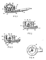
- Figure 1 is a perspective view of a pipe according to the present invention having a portion of the bowl and stem removed, showing the cartridge and the bowl conversion member.
- Figure 2 is a sectional view of the bowl/stem arrangement of the pipe of Figure 1, illustrating the placement of the cartridge and the bowle conversion member of the present invention.
- Figure 3 is a sectional view of another pipe of the present invention, having its bowl modified to directly accept the cartridge of the present invention and illustrating one cartridge ejection means.
- Figure 4 is a top view of the pipe of Figure 3, illustrating the relative size of the preferred fuel element to the bowl and one preferred arrangement of fuel element passageways.
- The embodiment of the invention illustrated in Figures 1 and 2, has about the same overall dimensions as a conventional pipe. It includes a
conventional pipe 10 comprising abowl 12, astem 14, an annularbowl conversion member 16, and areplaceable cartridge 18. Thecartridge 18 includes a short, combustiblecarbonaceous fuel element 20 inserted into a heatconductive container 22, which container encloses asubstrate 24 bearing at least one aerosol forming substance.Cartridge 18 fits intobowl conversion member 16 making the cartridge useful in any conventional pipe. - In the embodiment shown in Figures 1 and 2, the
carbonaceous fuel element 20 is about 10 mm long and about 4.5 mm in diameter, and is provided with sevenpassageways 26, as illustrated in Figure 4. The heatconductive container 22, is a metal, e.g., aluminum, tube about 30 mm long and about 4.5 mm in diameter. Thesubstrate 24 may be, for example about 200 mg of granular alumina, bearing one or more aerosol forming substances such as glycerin, tobacco extracts, and/or flavors. The bottom end of the container is sealed to retain the substrate but includes at least one opening 27 to allow the passage of aerosol forming gases to thepassageway 28 in thestem 14. Thefuel element 20 extends about 7 mm beyond the open end of thecontainer 22. - The
bowl conversion member 16 is generally an annular member designed to receive up to about 5 mm of the bottom portion of thecartridge 16. Theconversion member 16 is also designed to fit snugly into the bottom of thepipe bowl 12. The hole in theannular member 16 is preferably aligned with the opening topassageway 28 in thestem 14 of the pipe. - In preferred embodiments, such as the illustrated embodiments, the cartridge does not extend beyond the rim of the pipe bowl. Generally, the distance from the top of the fuel element in the cartridge and the rim of the pipe bowl is at least about 1 mm, preferably about 3 mm or more. This recessed cartridge decreases the possibility that careless handling will cause a fire or burn the user.
- As illustrated in Figure 3, the
pipe bowl 12 may be shaped to accept thecartridge 18 and may include a cartridge ejection means 30. As illustrated in Figure 3, one such ejection means comprises anelongated member 32, slidably mounted through the bottom of thepipe bowl 12, to engage the bottom of thecartridge 18. Theelongated member 32 is designed so as not to obstruct thepassageway 28 ofstem 14 and may include an enlargedknob 34. - Upon lighting, the fuel element burns, generating the heat used to volatilize the aerosol forming substance or substances in the aerosol generating means. Because the preferred fuel element is relatively short, the hot, burning fire cone is always close to the aerosol generating means, which maximizes heat transfert to the aerosol generating means and resultant production of aeroso, especially when the preferred heat conducting member is used.
- The small size and burning characteristics of the preferred fuel elements employed in the present invention ensure that the fuel element will begin to burn over substantially all of its exposed length within a few puffs. Thus, that portion of the fuel element adjacent to the aerosol generator becomes hot quickly, which significantly increases heat transfer to the aerosol generator, especially during the early and middle puffs. Control of heat transfer to the aerosol generating means is important both in terms of transferring enough heat to produce sufficient aerosol and in terms of avoiding the transfert of so much heat that the aerosol former is degraded. Heat transfer is enhanced by the heat conductive material employed in the preferred conductive container for the aerosol forming substances, which aids in the distribution of heat to that portion of the aerosol forming substance which is physically remote from the fuel. This helps produce good aerosol, especially in the early and middle puffs. The control of heat transfer form the fuel element to the aerosol generating means is also aided by the presence of a plurality of passageways in the fuel element, which allow the rapid passage of hot gases to the aerosol generator, especially during puffing.
- Because the aerosol forming substance is physically separate from the fuel element, the aerosol forming substance is exposed to substantially lower temperatures than are generated by the burning fuel, thereby minimizing the possibility of its thermal degradation. This also results in aerosol production almost exclusively during puffing, with little or no aerosol production from the aerosol generating means during smolder.
- In the preferred embodiments of the invention, the short carbonaceous fuel element and the aerosol generator cooperate to provide a system which is capable of producing substantial quantities of aerosol, on virtually every puff. The close proximity of the fire cone to the aerosol generator after a few puffs, together with the conductive elements of the container, result in high heat delivery both during puffing and during the relatively long period of smolder between puffs.
- In general, the combustible fuel elements which may be employed in the cartridges of the present invention have a diameter of at least about 2 mm, preferably from about 4 mm to 8 mm, and are generally less than about 30 mm long. Advantageously the fuel element is about 20 mm or less in length, preferably about 15 mm or less in length. The density of the fuel elements employed herein may range from about 0.5 g/cc to about 1.5 g/cc, as measured by mercury porosity. Preferably the density is greater that about 0.7 g/cc, more preferably greater than about 0.8 g/cc.
- The preferred fuel elements employed herein are primarily formed of a carbonaceous material. Carbonaceous fuel elements are preferably from about 5 to 15 mm, more preferably, from about 8 to 12 mm in length. Preferably, the carbon content of these fuel elements is at least 60 to 70%, most preferably about 80% or more, by weight. High carbon content fuel elements are preferred because they produce minimal pyrolysis and incomplete combustion products, little or no visible sidestream smoke, and minimal ash, and have high heat capacity. However, lower carbon content fuel elements e.g., about 50 to 60% carbon by weight, are within the scope of this invention, especially where a minor amount of tobacco, tobacco extract, or a nonburning inert filler is used.
- Also, while not preferred, other fuel materials may be employed in the cartridge, such as tobacco, tobacco substitutes and the like, provided that they generate and conduct sufficient heat to the aerosol generating means to produce the desired level of aerosol from the aerosol forming material, as discussed above. Where such other materials are used, it is much preferred to include carbon in the fuel, preferably in amounts of at least about 20% to 40% by weight, more preferably at least about 50% by weight, and most preferably at least about 65% to 70% by weight, the balance being the other fuel components, including any binder, burn modifiers, moisture, etc.
- The carbonaceous materials used in or as the preferred fuel element may be derived from virtually any of the numerous carbon sources known to those skilled in the art. Preferably, the carbonaceous material is obtained by the pyrolysis or carbonization of cellulosic materials, such as wood, cotton, rayon, tobacco, coconut, paper, and the like, although carbonaceous materials from other sources may be used.
- In most instances, the carbonaceous fuel elements should be capable of being ignited by a conventional cigarette lighter without the use of an oxidizing agent. Burning characteristics of this type may generally be obtained from a cellulosic material which has been pyrolyzed at temperatures between about 400°C to about 1000°C, preferably between about 500°C to about 950°C, most preferably at about 750°C, in an inert atmosphere or under a vacuum. The pyrolysis time is not believed to be critical, as long as the temperature at the center of the pyrolyzed mass has reached the aforesaid temperature range for at least a few, e.g., about 15, minutes. A slow pyrolysis, employing gradually increasing temperatures over many hours, is believed to produce a uniform material with a high carbon yield. Preferably, the pyrolyzed material is then cooled, ground to a fine powder, and heated in an inert gas stream at a temperature between about 650°C to 850°C to remover volatiles prior to further processing.
- While undesirable in most cases, carbonaceous materials which require the use of an oxidizing agent to render them ignitable by a cigarette lighter are within the scope of this invention, as are carbonaceous materials which require the use of a glow retardant or other type of combustion modifying agent. Such combustion modifying agents are disclosed in many patents and publications and are well known to those of ordinary skill in the art.
- In certain preferred embodiments, the carbonaceous fuel elements are substantially free of volatile organic material. By that it is meant that the fuel element is not purposely impregnated or mixed with substantial amounts of volatile organic materials, such as volatile aerosol forming or flavoring agents, which could degrade in the burning fuel. However, small amounts of materials, e.g., water, which are naturally adsorbed by the carbon in the fuel element, may be present therein. Similarly, small amounts of aerosol forming substances may migrate from the aerosol generating means and thus may also be present in the fuel.
- In other preferred embodiments, the fuel element may contain minor amounts of tobacco, tobacco extracts, and/or other materials, primarily to add flavor to the aerosol. Amounts of these additives may range up to about 25 weight percent or more, depending upon the additive, the fuel element, and the desired burning characteristics. Tobacco and/or tobacco extracts may be added to carbonaceous fuel elements at about 10 to 20 weight percent, thereby providing tobacco flavors to the mainstream and tobacco aroma to the sidestream akin to a conventional cigarette, without affecting the Ames test activity of the product.
- A preferred carbonaceous fuel element is a pressed or extruded mass of carbon prepared from a powdered carbon and a binder, by pressure forming or extrusion techniques. A preferred activated carbon for such a fuel element is PCB-G, and a preferred non-activated carbon is PXC, both available from Calgon Carbon Corporation, Pittsburgh, PA. Other preferrednonactivated carbons for pressure forming are prepared from pyrolyzed cotton or pyrolyzed papers, such as non-talc containing grades of Grande Prairie Canadian Kraft, available from the Buckeye Cellulose Corporation of Memphis, TN.
- The binders which may be used in preparing such a fuel element are well known in the art. A preferred binder is sodium carboxymethylcellulose (SCMC), which may be used alone, which is preferred, or in conjunction with materials such as sodium chloride, vermiculite, bentonite, calcium carbonate, and the like. Other useful binders include gums, such as guar gum, and other cellulose derivatives, such as methylcellulose and carboxymethylcellulose (CMC).
- A wide range of binder concentrations can be utilized. Preferably, the amount of binder is limited to minimize contribution of the binder to undesirable combustion products. On the other hand, sufficient binder must be included to hold the fuel element together during manufacture and use. The amount used will thus depend on the cohesiveness of the carbon in the fuel.
- In general, an extruded carbonaceous fuel may be prepared by admixing from about 50 to 99 weight percent, preferably about 80 to 95 weight percent, of the carbonaceous material, with from 1 to 50 weight percent, preferably about 5 to 20 weight percent of the binder, with sufficient water to make a paste having a stiff dough-like consistency. Minor amounts, e.g., up to about 35 weight percent, preferably about 10 to 20 weight percent, of tobacco, tobacco extract, and the like, may be added to the paste with additional water, if necessary, to maintain a stiff dough consistency. The dough is then formed, e.g., by using a standard ram or piston type extruder into the desired shape, and dried, preferably at about 95°C to reduce the moisture content to about 2 to 7 percent by weight.
- Carbonaceous fuel elements are preferably provided with one or more longitudinally extending passageways. These passageways help to control transfer of heat from the fuel element to the aerosol generating means, which is important both in terms of transferring enough heat to produce sufficient aerosol and in terms of avoiding the transfer of so much heat that the aerosol former is degraded. Generally, these passageways provide porosity and increase early heat transfer to the substrate by increasing the amount of hot gases which reach the substrate. They also tend to increase the rate of burning.
- These passageways may be formed during the extrusion step. Alternatively, or additionally, the passageways may be formed using conventional drilling techniques. Generally, a large number of passageways, e.g., about 5 to 9 or more, especially with relatively wide spacings between the passageways, such as the configuration illustrated in Figure 4 is preferred. If desired, the lighting end of the fuel elements may be tapered or reduced in diameter by machining, molding, or the like, to improve lightability.
- A high quality fuel element may be formed by casting a thin slurry of the carbon/binder mixture (with or without additional components) into a sheet, drying the sheet, regarding the dried sheet into a powder, forming a stiff paste with water, and extruding the paste as described above.
- If desired, carbon/binder fuel elements (without tobacco, and the like) may be pyrolyzed after formation, for example, to about 650°C for two hours, to convert the binder to carbon and thereby form a virtually 100% carbon fuel element.
- The fuel elements of the present invention also may contain one or more additives to improve burning, such as up to about 5 weight percent of sodium chloride to improve smoldering characteristics and as a glow retardant.
- Also, up to about 5, preferably from about 1 to 2, weight percent of potassium carbonate may be included to control flammability. Additives to improve physical characteristics, such as clays like kaolins, serpentines, attapulgites and the like also may be used.
- The aerosol generating means used in the cartridge of the present invention is physically separate from the fuel element. By physically separate it is meant that the substrate, container, or chamber which contains the aerosol forming materials is not mixed with, or a part of, the fuel element. This arrangement helps reduce or eliminate thermal degradation of the aerosol forming substance and the presence of sidestream smoke.
- While not a part of the fuel element, the aerosol generating means generally abuts or is connected to the fuel element such that the fuel element and the aerosol generating means are in a conductive heat exchange relationship. Preferably, the conductive heat exchange relationship is achieved by providing a heat conductive member, such as a metal foil, recessed from the lighting end of the fuel element, which efficiently conducts or transfers heat from the burning fuel element to the aerosol generating means.
- The preferred container for the aerosol generating means may vary in length from about 5 mm to about 40 mm, preferably from about 15 mm to 35 mm, and most preferably from about 20 mm to 30 mm. The diameter of the aerosol generating means should be at least about 2 mm, and preferably from about 4 mm to 8 mm.
- Preferably, the aerosol generating means includes one or more thermally stable materials which carry one or more aerosol forming substances. As used herein, a "thermally stable" material is one capable of withstanding the high, albeit controlled, temperatures, e.g., from about 400°C to about 600°C, which may eventually exist near the fuel, without significant decomposition or burning. The use of such material is believed to help maintain the simple "smoke" chemistry of the aerosol, as evidenced by a lack of Ames test activity in the preferred embodiments. While not preferred, other aerosol generating means, such as heat rupturable microcapsules, or solid aerosol forming substances, are within the scope of this invention, provided they are capable of releasing sufficient aerosol forming vapors to satisfactorily resemble tobacco smoke.
- Thermally stable materials which may be used as the carrier or substrate for the aerosol forming substance are well known to those skilled in the art. Useful carriers should be porous, and must be capable of retaining an aerosol forming compound and releasing a potential aerosol forming vapor upon heating by the fuel. Useful thermally stable materials include adsorbent carbons, such as porous grade carbons, graphite, activated, or non-activated carbons, and the like, such as PC-25 and PG-60 available from Union Carbide Corp., Danbury, CT, as well as SGL carbon, available from Calgon. Other suitable materials include inorganic solids, such as ceramics, glass, alumina, vermiculite, clays such as bentonite, and the like. Carbon and alumina substrates are preferred.
- An especially useful alumina substrate is available from the Davison Chemical Division of W.R. Grace & Co. under the designation SMR-14-1896. Before use, this alumina is sintered at elevated temperatures, e.g., greater than 1000°C, washed, and dried.
- It has been found that suitable particulate substrates also may be formed from carbon, tobacco, or mixtures of carbon and tobacco, into densified particles in a one-step process using a machine made by Fuji Paudal KK of Japan, and sold under the trade name of "Marumerizer." This apparatus is described in German Patent No. 1,294,351 and U.S. Patent No. 3,277,520 (now reissued as No. 27,214) as well as Japanese published specification No. 8684/1967.
- The aerosol forming substance or substances used in the cartridges of the present invention must be capable of forming an aerosol at the temperatures present in the aerosol generating means upon heating by the burning fuel element. Such substances preferably will be composed of carbon, hydrogen and oxygen, but they may include other materials. Such substances can be in solid, semisolid, or liquid form. The boiling or sublimation point of the substance and/or the mixture of substances can range up to about 500°C. Substances having these characteristics include: polyhydric alcohols, such as glycerin, triethylene glycol, and propylene glycol, as well as aliphatic esters of mono-, di-, or poly-carboxylic acids, such as methyl stearate, dodecandioate, dimethyl tetradodecandioate, and others.
- The preferred aerosol forming substances are polyhydric alcohols, or mixtures of polyhydric alcohols. More preferred aerosol formers are selected from glycerine, triethylene glycol and propylene glycol.
- When a substrate material is employed as a carrier, the aerosol forming substance may be dispersed on or within the substrate in a concentration sufficient to permeate or coat the material, by any known technique. For example, the aerosol forming substance may be applied full strength or in a dilute solution by dipping, spraying, vapor deposition, or similar techniques. Solid aerosol forming components may be admixed with the substrate material and distributed evenly throughout prior to formation of the final substrate.
- While the loading of the aerosol forming substance will vary from carrier to carrier and from aerosol forming substance to aerosol forming substance, the amount of liquid aerosol forming substances may generally vary from about 20 mg to about 120 mg, preferably from about 35 mg to about 85 mg, and most preferably from about 45 mg to about 65 mg. As much as possible of the aerosol former carried on the substrate should be delivered to the user as WTPM. Preferably, above about 2 weight percent, more preferably above about 15 weight percent, and most preferably above about 20 weight percent of the aerosol former carried on the substrate is delivered to the user as WTPM.
- The aerosol generating means also may include one or more volatile flavoring agents, such as menthol, vanillin, artificial coffee, tobacco extracts, nicotine, caffeine, liquors, and other agents which impart flavor to the aerosol. It also may include any other desirable volatile solid or liquid materials.
- One particularly preferred aerosol generating means comprises the aforesaid alumina substrate containing spray dried tobacco extract, tobacco flavor modifiers, such as levulinic acid, one or more flavoring agents, and an aerosol forming agent, such as glycerin. In certain preferred embodiments, this substrate may be mixed with densified tobacco particles, such as those produced on a "Marumerizer."
- Articles of the type disclosed herein may be used or may be modified for use as drug delivery articles, for delivery of volatile pharmacologically or physiologically active materials such as ephedrine, metaproterenol, terbutaline, or the like.
- The heat conducting member preferably employed in fabricating the cartridge of the present invention is typically a metallic foil, such as aluminum foil, varying in thickness from less than about 0.01 mm to about 0.1 mm, or more. The thickness and/or the type of conducting material may be varied (e.g., Grafoil, from Union Carbide) to achieve virtually any desired degree of heat transfer. As shown in the illustrated embodiment, the heat conducting material preferably contacts or overlaps a portion of the fuel element, and forms the container which encloses the aerosol forming substance.
- Preferably, the heat conducting member extends over no more than about one-half the length of the fuel element. More preferably, the heat conducting member overlaps or otherwise contacts no more than about the rear 5 mm of the fuel element. Such members help to extinguish the fuel element when it has been consumed to the point of contact with the conducting member by acting as a heat sink.
- The diameter of the cartridges of the present invention may be varied depending upon the amount of aerosol to be delivered and the desired number of puffs to be generated. For example, the 10 mm fuel element/30 mm long container of the illustrated embodiments provides from about 10 to 15 puffs with large quantities of aerosol during typical smoking. By adjusting the dimensions of the cartridge components and/or the aerosol generating means, both the quantity of aerosol produced and the number of available puffs can be adjusted.
- In certain embodiments of the invention, the cartridge will be attached to the bowl of a conventional pipe by means of a bowl conversion member. One such conversion member is illustrated in Figures 1 and 2. This bowl conversion member should be prepared from a heat resistant material, preferably the same material as the pipe in which it is used. Examples of such materials include briarwood, clays, and the like. The conversion member should be shaped to fit snugly inside the pipe bowl. The draft hole at the bottom of the pipe bowl must not be blocked by the conversion member. Gases drawn from the cartridge flow into the draft hole of the pipe bowl, pass to the stem and are delivered to the user akin to conventional pipe tobacco smoke.
- In other embodiments, such as the pipe illustrated in Figures 3 and 4, the pipe bowl itself may be designed to accept the cartridge of the present invention, without the need of any adapter/conversion member. Furthermore, in such embodiments a cartridge ejection means may advantageously be provided in order to facilitate the removal of spent cartridges from the pipe bowl. One such ejection means is illustrated in Figure 3. This ejection means operates as a slidable shaft which contacts the bottom portion of the cartridge and when pressed upward, exerts force on the cartridge removing it from its position within the bowl. Other ejection means will be readily apparent to the skilled artisan upon consideration of this disclosure.
- The aerosol produced by the preferred articles of the present invention is chemically simple, consisting essentially of air, oxides of carbon, aerosol former including any desired flavors or other desired volatile materials, water and trace amounts of other materials. The WTPM produced by the preferred articles of this invention has no mutagenic activity as measured by the Ames test, i.e., there is no significant dose response relationship between the WTPM produced by preferred articles of the present invention and the number of revertants occurring in standard test microorganisms exposed to such products. According to the proponents of the Ames test, a significant dose dependent response indicates the presence of mutagenic materials in the products tested. See Ames et al., Mut. Res., 31: 347-364 (1975); Nagas et al., Mut. Res., 42: 335 (1977).
- A further benefit from the preferred embodiments of the present invention is the relative lack of ash produced during use in comparison to ash from a conventional pipe. As the preferred carbon fuel element is burned, it is essentially converted to oxides of carbon, with relatively little ash generation.
- The smoking article of the present invention will be further illustrated with reference to the following example which will aid in the understanding of the present invention, but which is not to be construed as a limitation thereof. All percentages reported herein, unless otherwise specified, are percent by weight. All temperatures are expressed in degrees Celsius and are uncorrected.
- A pipe substantially as illustrated in Figure 1 was prepared in the following manner.
- A conventional briar wood pipe having a bowl about 40 mm deep, about 30 mm outer diameter, and about 18 mm inner diameter, was modified by inserting therein an adapter which consisted of a section of briar wood, about 17 mm wide, about 5 mm thick, having a centrally drilled hole of about 5 mm diameter. This adapter fit snugly into the pipe bowl and centered the hole above the bottom of the pipe bowl.
- The carbon was prepared by pyrolyzing Grande Prairie Canadian Kraft paper (hardwood, non-talc grade) at a carbonizing temperature of 550°C for 8 hours. After cooling, the carbon was ground to an average particle size of less than about 10 microns. The powdered carbon was then heated under a nitrogen sweep gas to a temperature of 850°C and held at that temperature for 8 hours.
- A fuel element (10 mm long, 4.5 mm o.d.) having an apparent (bulk) density of about 0.86 g/cc, was prepared by admixing the carbon powder (89 weight percent), SCMC binder (10 wt. percent) and K₂CO₃ (1 wt. percent) with sufficient water to make an extrudable paste.
- The fuel element was extruded with seven holes (each about 0.6 mm diameter) in a somewhat closely spaced arrangement (similar to Fig. 4) with a core diameter, i.e., the diameter of the smallest circle which will circumscribe the holes in the fuel element) of about 2.6 mm and spacing between the holes of about 0.3 mm.
- The capsule for the aerosol generating means was prepared from drawn aluminum tubing (from Niemand, Inc.), about 32 mm in length, having an outer diameter of about 4.5 mm. The rear 2 mm of the capsule was crimped to seal the mouth end of the capsule. At the mouth end, two slots, each about 0.65 mm × 3.45 mm were cut into the sealed wall.
- High surface area alumina (surface area = 280 m²/g) from W.R. Grace & Co. (designated SMR-14-1896), having a mesh size of from _8 to +14 (U.S.) was sintered at a soak temperature above about 1400°C, preferably from about 1400° to 1550°C, for about one hour and cooled. The alumina was washed with water.
- The alumina (640 mg) was dried to a moisture content of from about 1 to 5, preferably about 3.5, weight percent. This material was then treated with a mixture of 233 mg of glycerin and a flavor mixture; comprising (by weight) 0.25% of phenyl ethyl alcohol, 0.35% Tabac (chocolate) and 0.35% coffee. The capsule was filled with a 200 mg of a 1: 1 mixture of the this treated alumina and densified (i.e., Marumerized) flue cured tobacco having a density of about 0.8 g/cc, loaded with about 15 wt. percent glycerin.
- The fuel element was inserted into the open end of the filled capsule to a depth of about 3 mm, forming the preferred cartridge of the present invention. This cartridge was inserted into the pipe bowl converter to a depth of about 5 mm, thereby leaving about 3 mm of clearance between the top of the fuel element and the rim of the pipe bowl.
- Upon smoking this article, good aerosol delivery was achieved on virtually each of the 11 puffs taken.
- Flavor was good and there was no sidestream smoke, and very little ash after the fuel element was consumed.
- The present invention has been described in detail, including the preferred embodiments thereof.
Claims (5)
Priority Applications (1)
| Application Number | Priority Date | Filing Date | Title |
|---|---|---|---|
| AT87103278T ATE64829T1 (en) | 1986-03-14 | 1987-03-07 | WHISTLE WITH INTERCHANGEABLE CARTRIDGE. |
Applications Claiming Priority (2)
| Application Number | Priority Date | Filing Date | Title |
|---|---|---|---|
| US840114 | 1986-03-14 | ||
| US06/840,114 US4708151A (en) | 1986-03-14 | 1986-03-14 | Pipe with replaceable cartridge |
Publications (2)
| Publication Number | Publication Date |
|---|---|
| EP0241698A1 EP0241698A1 (en) | 1987-10-21 |
| EP0241698B1 true EP0241698B1 (en) | 1991-07-03 |
Family
ID=25281487
Family Applications (1)
| Application Number | Title | Priority Date | Filing Date |
|---|---|---|---|
| EP87103278A Expired - Lifetime EP0241698B1 (en) | 1986-03-14 | 1987-03-07 | Pipe with replaceable cartridge |
Country Status (24)
| Country | Link |
|---|---|
| US (1) | US4708151A (en) |
| EP (1) | EP0241698B1 (en) |
| JP (1) | JPS62224277A (en) |
| KR (1) | KR870008539A (en) |
| CN (1) | CN87101954A (en) |
| AT (1) | ATE64829T1 (en) |
| AU (1) | AU6986987A (en) |
| BG (1) | BG49494A3 (en) |
| BR (1) | BR8701137A (en) |
| DD (1) | DD259348A5 (en) |
| DE (1) | DE3771106D1 (en) |
| DK (1) | DK132187A (en) |
| ES (1) | ES2023641B3 (en) |
| FI (1) | FI871105A7 (en) |
| HU (1) | HUT45879A (en) |
| IL (1) | IL81732A0 (en) |
| MA (1) | MA20898A1 (en) |
| MX (1) | MX163154B (en) |
| MY (1) | MY100019A (en) |
| PH (1) | PH22600A (en) |
| PL (1) | PL264656A1 (en) |
| PT (1) | PT84483B (en) |
| YU (1) | YU40987A (en) |
| ZA (1) | ZA871368B (en) |
Cited By (3)
| Publication number | Priority date | Publication date | Assignee | Title |
|---|---|---|---|---|
| US8469036B2 (en) | 2003-11-07 | 2013-06-25 | U.S. Smokeless Tobacco Company Llc | Tobacco compositions |
| US8627828B2 (en) | 2003-11-07 | 2014-01-14 | U.S. Smokeless Tobacco Company Llc | Tobacco compositions |
| US12465076B2 (en) | 2021-11-05 | 2025-11-11 | Martin D. Katz | Fresh / clean smoking system |
Families Citing this family (199)
| Publication number | Priority date | Publication date | Assignee | Title |
|---|---|---|---|---|
| US4991606A (en) * | 1988-07-22 | 1991-02-12 | Philip Morris Incorporated | Smoking article |
| US4981522A (en) * | 1988-07-22 | 1991-01-01 | Philip Morris Incorporated | Thermally releasable flavor source for smoking articles |
| US4966171A (en) * | 1988-07-22 | 1990-10-30 | Philip Morris Incorporated | Smoking article |
| US5345951A (en) * | 1988-07-22 | 1994-09-13 | Philip Morris Incorporated | Smoking article |
| US5076296A (en) * | 1988-07-22 | 1991-12-31 | Philip Morris Incorporated | Carbon heat source |
| US4947874A (en) * | 1988-09-08 | 1990-08-14 | R. J. Reynolds Tobacco Company | Smoking articles utilizing electrical energy |
| US4955399A (en) * | 1988-11-30 | 1990-09-11 | R. J. Reynolds Tobacco Company | Smoking article |
| US5040552A (en) * | 1988-12-08 | 1991-08-20 | Philip Morris Incorporated | Metal carbide heat source |
| US5016654A (en) * | 1988-12-21 | 1991-05-21 | R. J. Reynolds Tobacco Company | Flavor substances for smoking articles |
| US5038802A (en) * | 1988-12-21 | 1991-08-13 | R. J. Reynolds Tobacco Company | Flavor substances for smoking articles |
| US4991596A (en) * | 1989-07-11 | 1991-02-12 | R. J. Reynolds Tobacco Company | Smoking article |
| US4938236A (en) * | 1989-09-18 | 1990-07-03 | R. J. Reynolds Tobacco Company | Tobacco smoking article |
| US4967774A (en) * | 1989-10-11 | 1990-11-06 | R. J. Reynolds Tobacco Company | Smoking article with improved means for retaining the fuel element |
| US5188130A (en) | 1989-11-29 | 1993-02-23 | Philip Morris, Incorporated | Chemical heat source comprising metal nitride, metal oxide and carbon |
| US5027837A (en) * | 1990-02-27 | 1991-07-02 | R. J. Reynolds Tobacco Company | Cigarette |
| US5099861A (en) * | 1990-02-27 | 1992-03-31 | R. J. Reynolds Tobacco Company | Aerosol delivery article |
| US5156170A (en) * | 1990-02-27 | 1992-10-20 | R. J. Reynolds Tobacco Company | Cigarette |
| US5415186A (en) * | 1990-08-15 | 1995-05-16 | R. J. Reynolds Tobacco Company | Substrates material for smoking articles |
| US5396911A (en) * | 1990-08-15 | 1995-03-14 | R. J. Reynolds Tobacco Company | Substrate material for smoking articles |
| US5065776A (en) | 1990-08-29 | 1991-11-19 | R. J. Reynolds Tobacco Company | Cigarette with tobacco/glass fuel wrapper |
| US5105837A (en) * | 1990-08-28 | 1992-04-21 | R. J. Reynolds Tobacco Company | Smoking article with improved wrapper |
| US5962662A (en) * | 1990-12-20 | 1999-10-05 | R.J. Reynolds Tobacco Company | Method for producing a flavorful and aromatic composition for use in smoking articles |
| US5247949A (en) * | 1991-01-09 | 1993-09-28 | Philip Morris Incorporated | Method for producing metal carbide heat sources |
| US5203355A (en) * | 1991-02-14 | 1993-04-20 | R. J. Reynolds Tobacco Company | Cigarette with cellulosic substrate |
| US5348027A (en) * | 1991-02-14 | 1994-09-20 | R. J. Reynolds Tobacco Company | Cigarette with improved substrate |
| US5146934A (en) * | 1991-05-13 | 1992-09-15 | Philip Morris Incorporated | Composite heat source comprising metal carbide, metal nitride and metal |
| US5178167A (en) * | 1991-06-28 | 1993-01-12 | R. J. Reynolds Tobacco Company | Carbonaceous composition for fuel elements of smoking articles and method of modifying the burning characteristics thereof |
| US5285798A (en) * | 1991-06-28 | 1994-02-15 | R. J. Reynolds Tobacco Company | Tobacco smoking article with electrochemical heat source |
| US5235992A (en) * | 1991-06-28 | 1993-08-17 | R. J. Reynolds Tobacco Company | Processes for producing flavor substances from tobacco and smoking articles made therewith |
| US5246018A (en) * | 1991-07-19 | 1993-09-21 | Philip Morris Incorporated | Manufacturing of composite heat sources containing carbon and metal species |
| US5413122A (en) * | 1992-02-18 | 1995-05-09 | R. J. Reynolds Tobacco Company | Method of providing flavorful and aromatic compounds |
| US5345955A (en) * | 1992-09-17 | 1994-09-13 | R. J. Reynolds Tobacco Company | Composite fuel element for smoking articles |
| PH30299A (en) * | 1993-04-07 | 1997-02-20 | Reynolds Tobacco Co R | Fuel element composition |
| US5468266A (en) * | 1993-06-02 | 1995-11-21 | Philip Morris Incorporated | Method for making a carbonaceous heat source containing metal oxide |
| US6591841B1 (en) | 1996-08-01 | 2003-07-15 | Jackie Lee White | Method of providing flavorful and aromatic tobacco suspension |
| US8022095B2 (en) * | 1996-08-16 | 2011-09-20 | Pozen, Inc. | Methods of treating headaches using 5-HT agonists in combination with long-acting NSAIDs |
| EP1047308A4 (en) * | 1998-01-06 | 2007-05-02 | Philip Morris Prod | Cigarette having reduced sidestream smoke |
| US5996589A (en) * | 1998-03-03 | 1999-12-07 | Brown & Williamson Tobacco Corporation | Aerosol-delivery smoking article |
| US6164287A (en) | 1998-06-10 | 2000-12-26 | R. J. Reynolds Tobacco Company | Smoking method |
| US6298858B1 (en) | 1998-11-18 | 2001-10-09 | R. J. Reynolds Tobacco Company | Tobacco flavoring components of enhanced aromatic content and method of providing same |
| USD436686S1 (en) | 1999-09-07 | 2001-01-23 | Kabushiki Kaisha Fujisawa | Pipe |
| NZ529417A (en) | 2001-05-24 | 2006-11-30 | Alexza Pharmaceuticals Inc | Delivery of alprazolam, estazolam, midazolam or triazolam through an inhalation route |
| US7645442B2 (en) | 2001-05-24 | 2010-01-12 | Alexza Pharmaceuticals, Inc. | Rapid-heating drug delivery article and method of use |
| US7585493B2 (en) | 2001-05-24 | 2009-09-08 | Alexza Pharmaceuticals, Inc. | Thin-film drug delivery article and method of use |
| US7766013B2 (en) | 2001-06-05 | 2010-08-03 | Alexza Pharmaceuticals, Inc. | Aerosol generating method and device |
| CA2446904A1 (en) | 2001-05-24 | 2003-04-03 | Alexza Pharmaceuticals, Inc. | Delivery of drug esters through an inhalation route |
| US20070122353A1 (en) | 2001-05-24 | 2007-05-31 | Hale Ron L | Drug condensation aerosols and kits |
| WO2002094242A1 (en) * | 2001-05-24 | 2002-11-28 | Alexza Molecular Delivery Corporation | Delivery of rizatriptan or zolmitriptan through an inhalation route |
| US7498019B2 (en) | 2001-05-24 | 2009-03-03 | Alexza Pharmaceuticals, Inc. | Delivery of compounds for the treatment of headache through an inhalation route |
| US7458374B2 (en) | 2002-05-13 | 2008-12-02 | Alexza Pharmaceuticals, Inc. | Method and apparatus for vaporizing a compound |
| US7090830B2 (en) | 2001-05-24 | 2006-08-15 | Alexza Pharmaceuticals, Inc. | Drug condensation aerosols and kits |
| WO2003041693A1 (en) * | 2001-11-09 | 2003-05-22 | Alexza Molecular Delivery Corporation | Delivery of diazepam through an inhalation route |
| EP1468618B1 (en) * | 2001-12-28 | 2008-07-09 | Japan Tobacco Inc. | Smoking implement |
| EP1503744A1 (en) | 2002-05-13 | 2005-02-09 | Alexza Molecular Delivery Corporation | Delivery of drug amines through an inhalation route |
| US20040105818A1 (en) | 2002-11-26 | 2004-06-03 | Alexza Molecular Delivery Corporation | Diuretic aerosols and methods of making and using them |
| US7550133B2 (en) | 2002-11-26 | 2009-06-23 | Alexza Pharmaceuticals, Inc. | Respiratory drug condensation aerosols and methods of making and using them |
| CN101371843B (en) | 2002-11-26 | 2012-09-26 | 艾利斯达医药品公司 | Use of loxapine and amoxapine for the preparation of a medicament for the treatment of pain |
| US7913688B2 (en) | 2002-11-27 | 2011-03-29 | Alexza Pharmaceuticals, Inc. | Inhalation device for producing a drug aerosol |
| GB2397007A (en) * | 2003-01-08 | 2004-07-14 | Jonathan Richard Swift | Smoking-type device for generating a vapour for inhalation |
| ATE510174T1 (en) | 2003-05-21 | 2011-06-15 | Alexza Pharmaceuticals Inc | IMPACT LIT INDEPENDENT HEATING UNIT |
| US7290549B2 (en) * | 2003-07-22 | 2007-11-06 | R. J. Reynolds Tobacco Company | Chemical heat source for use in smoking articles |
| US7540286B2 (en) | 2004-06-03 | 2009-06-02 | Alexza Pharmaceuticals, Inc. | Multiple dose condensation aerosol devices and methods of forming condensation aerosols |
| US20050274390A1 (en) * | 2004-06-15 | 2005-12-15 | Banerjee Chandra K | Ultra-fine particle catalysts for carbonaceous fuel elements |
| AU2004322756B2 (en) | 2004-08-12 | 2011-04-14 | Alexza Pharmaceuticals, Inc. | Aerosol drug delivery device incorporating percussively activated heat packages |
| US9675109B2 (en) * | 2005-07-19 | 2017-06-13 | J. T. International Sa | Method and system for vaporization of a substance |
| US11647783B2 (en) | 2005-07-19 | 2023-05-16 | Juul Labs, Inc. | Devices for vaporization of a substance |
| US20160345631A1 (en) | 2005-07-19 | 2016-12-01 | James Monsees | Portable devices for generating an inhalable vapor |
| US7726320B2 (en) | 2006-10-18 | 2010-06-01 | R. J. Reynolds Tobacco Company | Tobacco-containing smoking article |
| US20080216828A1 (en) | 2007-03-09 | 2008-09-11 | Alexza Pharmaceuticals, Inc. | Heating unit for use in a drug delivery device |
| US8991402B2 (en) | 2007-12-18 | 2015-03-31 | Pax Labs, Inc. | Aerosol devices and methods for inhaling a substance and uses thereof |
| EP2113178A1 (en) | 2008-04-30 | 2009-11-04 | Philip Morris Products S.A. | An electrically heated smoking system having a liquid storage portion |
| US7834295B2 (en) | 2008-09-16 | 2010-11-16 | Alexza Pharmaceuticals, Inc. | Printable igniters |
| EP2319334A1 (en) | 2009-10-27 | 2011-05-11 | Philip Morris Products S.A. | A smoking system having a liquid storage portion |
| GB2480122A (en) * | 2010-03-01 | 2011-11-09 | Oglesby & Butler Res & Dev Ltd | A vaporising device with removable heat transfer element |
| DE202010004671U1 (en) * | 2010-04-01 | 2010-07-08 | JÄNTSCH, André | Carrier for flavored and / or smoke-emitting fluids for use in hookahs |
| US9861772B2 (en) | 2010-05-15 | 2018-01-09 | Rai Strategic Holdings, Inc. | Personal vaporizing inhaler cartridge |
| US11344683B2 (en) | 2010-05-15 | 2022-05-31 | Rai Strategic Holdings, Inc. | Vaporizer related systems, methods, and apparatus |
| US10159278B2 (en) | 2010-05-15 | 2018-12-25 | Rai Strategic Holdings, Inc. | Assembly directed airflow |
| US9743691B2 (en) | 2010-05-15 | 2017-08-29 | Rai Strategic Holdings, Inc. | Vaporizer configuration, control, and reporting |
| US8757147B2 (en) | 2010-05-15 | 2014-06-24 | Minusa Holdings Llc | Personal vaporizing inhaler with internal light source |
| US9259035B2 (en) | 2010-05-15 | 2016-02-16 | R. J. Reynolds Tobacco Company | Solderless personal vaporizing inhaler |
| US9999250B2 (en) | 2010-05-15 | 2018-06-19 | Rai Strategic Holdings, Inc. | Vaporizer related systems, methods, and apparatus |
| US9095175B2 (en) | 2010-05-15 | 2015-08-04 | R. J. Reynolds Tobacco Company | Data logging personal vaporizing inhaler |
| US10136672B2 (en) | 2010-05-15 | 2018-11-27 | Rai Strategic Holdings, Inc. | Solderless directly written heating elements |
| US20120048963A1 (en) | 2010-08-26 | 2012-03-01 | Alexza Pharmaceuticals, Inc. | Heat Units Using a Solid Fuel Capable of Undergoing an Exothermic Metal Oxidation-Reduction Reaction Propagated without an Igniter |
| DE102011011676B4 (en) * | 2011-02-18 | 2015-02-19 | Severus Patent Ag | Smoke-free cigarette, cigar or pipe |
| US9078473B2 (en) | 2011-08-09 | 2015-07-14 | R.J. Reynolds Tobacco Company | Smoking articles and use thereof for yielding inhalation materials |
| TWI593365B (en) | 2011-08-16 | 2017-08-01 | 佩克斯實驗室股份有限公司 | Low temperature electron evaporation device and method |
| US9854839B2 (en) | 2012-01-31 | 2018-01-02 | Altria Client Services Llc | Electronic vaping device and method |
| US20130255702A1 (en) | 2012-03-28 | 2013-10-03 | R.J. Reynolds Tobacco Company | Smoking article incorporating a conductive substrate |
| US10004259B2 (en) | 2012-06-28 | 2018-06-26 | Rai Strategic Holdings, Inc. | Reservoir and heater system for controllable delivery of multiple aerosolizable materials in an electronic smoking article |
| US10517530B2 (en) | 2012-08-28 | 2019-12-31 | Juul Labs, Inc. | Methods and devices for delivering and monitoring of tobacco, nicotine, or other substances |
| US8881737B2 (en) | 2012-09-04 | 2014-11-11 | R.J. Reynolds Tobacco Company | Electronic smoking article comprising one or more microheaters |
| US8910639B2 (en) | 2012-09-05 | 2014-12-16 | R. J. Reynolds Tobacco Company | Single-use connector and cartridge for a smoking article and related method |
| US10117460B2 (en) | 2012-10-08 | 2018-11-06 | Rai Strategic Holdings, Inc. | Electronic smoking article and associated method |
| US9854841B2 (en) | 2012-10-08 | 2018-01-02 | Rai Strategic Holdings, Inc. | Electronic smoking article and associated method |
| US8910640B2 (en) | 2013-01-30 | 2014-12-16 | R.J. Reynolds Tobacco Company | Wick suitable for use in an electronic smoking article |
| US10031183B2 (en) | 2013-03-07 | 2018-07-24 | Rai Strategic Holdings, Inc. | Spent cartridge detection method and system for an electronic smoking article |
| US20140261486A1 (en) | 2013-03-12 | 2014-09-18 | R.J. Reynolds Tobacco Company | Electronic smoking article having a vapor-enhancing apparatus and associated method |
| US20140261487A1 (en) | 2013-03-14 | 2014-09-18 | R. J. Reynolds Tobacco Company | Electronic smoking article with improved storage and transport of aerosol precursor compositions |
| US9918495B2 (en) | 2014-02-28 | 2018-03-20 | Rai Strategic Holdings, Inc. | Atomizer for an aerosol delivery device and related input, aerosol production assembly, cartridge, and method |
| US9277770B2 (en) | 2013-03-14 | 2016-03-08 | R. J. Reynolds Tobacco Company | Atomizer for an aerosol delivery device formed from a continuously extending wire and related input, cartridge, and method |
| US9609893B2 (en) | 2013-03-15 | 2017-04-04 | Rai Strategic Holdings, Inc. | Cartridge and control body of an aerosol delivery device including anti-rotation mechanism and related method |
| US10653180B2 (en) | 2013-06-14 | 2020-05-19 | Juul Labs, Inc. | Multiple heating elements with separate vaporizable materials in an electric vaporization device |
| US9491974B2 (en) | 2013-03-15 | 2016-11-15 | Rai Strategic Holdings, Inc. | Heating elements formed from a sheet of a material and inputs and methods for the production of atomizers |
| US9220302B2 (en) | 2013-03-15 | 2015-12-29 | R.J. Reynolds Tobacco Company | Cartridge for an aerosol delivery device and method for assembling a cartridge for a smoking article |
| US10279934B2 (en) | 2013-03-15 | 2019-05-07 | Juul Labs, Inc. | Fillable vaporizer cartridge and method of filling |
| US9423152B2 (en) | 2013-03-15 | 2016-08-23 | R. J. Reynolds Tobacco Company | Heating control arrangement for an electronic smoking article and associated system and method |
| CN104116134B (en) * | 2013-04-27 | 2016-12-28 | 宁波市镇海捷登应用技术研究所 | A kind of tobacco pipe |
| CN104116137B (en) * | 2013-04-27 | 2016-08-10 | 宁波市镇海捷登应用技术研究所 | a pipe |
| KR20240136470A (en) | 2013-05-06 | 2024-09-13 | 쥴 랩스, 인크. | Nicotine salt formulations for aerosol devices and methods thereof |
| US11229239B2 (en) | 2013-07-19 | 2022-01-25 | Rai Strategic Holdings, Inc. | Electronic smoking article with haptic feedback |
| US10143231B2 (en) * | 2013-08-13 | 2018-12-04 | Philip Morris Products S.A. | Smoking article comprising a blind combustible heat source |
| EP3035812A1 (en) | 2013-08-21 | 2016-06-29 | JT International S.A. | Smoking article for a water-pipe |
| US10172387B2 (en) | 2013-08-28 | 2019-01-08 | Rai Strategic Holdings, Inc. | Carbon conductive substrate for electronic smoking article |
| US9839237B2 (en) | 2013-11-22 | 2017-12-12 | Rai Strategic Holdings, Inc. | Reservoir housing for an electronic smoking article |
| US10463069B2 (en) | 2013-12-05 | 2019-11-05 | Juul Labs, Inc. | Nicotine liquid formulations for aerosol devices and methods thereof |
| EP3928646B1 (en) | 2013-12-23 | 2025-03-26 | Juul Labs International Inc. | Vaporization device systems |
| USD842536S1 (en) | 2016-07-28 | 2019-03-05 | Juul Labs, Inc. | Vaporizer cartridge |
| US9549573B2 (en) | 2013-12-23 | 2017-01-24 | Pax Labs, Inc. | Vaporization device systems and methods |
| US10076139B2 (en) | 2013-12-23 | 2018-09-18 | Juul Labs, Inc. | Vaporizer apparatus |
| US10058129B2 (en) | 2013-12-23 | 2018-08-28 | Juul Labs, Inc. | Vaporization device systems and methods |
| US10159282B2 (en) | 2013-12-23 | 2018-12-25 | Juul Labs, Inc. | Cartridge for use with a vaporizer device |
| US20160366947A1 (en) | 2013-12-23 | 2016-12-22 | James Monsees | Vaporizer apparatus |
| USD825102S1 (en) | 2016-07-28 | 2018-08-07 | Juul Labs, Inc. | Vaporizer device with cartridge |
| US9974334B2 (en) | 2014-01-17 | 2018-05-22 | Rai Strategic Holdings, Inc. | Electronic smoking article with improved storage of aerosol precursor compositions |
| US10575558B2 (en) | 2014-02-03 | 2020-03-03 | Rai Strategic Holdings, Inc. | Aerosol delivery device comprising multiple outer bodies and related assembly method |
| US9451791B2 (en) | 2014-02-05 | 2016-09-27 | Rai Strategic Holdings, Inc. | Aerosol delivery device with an illuminated outer surface and related method |
| US20150224268A1 (en) | 2014-02-07 | 2015-08-13 | R.J. Reynolds Tobacco Company | Charging Accessory Device for an Aerosol Delivery Device and Related System, Method, Apparatus, and Computer Program Product for Providing Interactive Services for Aerosol Delivery Devices |
| US9833019B2 (en) | 2014-02-13 | 2017-12-05 | Rai Strategic Holdings, Inc. | Method for assembling a cartridge for a smoking article |
| US9839238B2 (en) | 2014-02-28 | 2017-12-12 | Rai Strategic Holdings, Inc. | Control body for an electronic smoking article |
| US9597466B2 (en) | 2014-03-12 | 2017-03-21 | R. J. Reynolds Tobacco Company | Aerosol delivery system and related method, apparatus, and computer program product for providing control information to an aerosol delivery device via a cartridge |
| US11696604B2 (en) | 2014-03-13 | 2023-07-11 | Rai Strategic Holdings, Inc. | Aerosol delivery device and related method and computer program product for controlling an aerosol delivery device based on input characteristics |
| US9877510B2 (en) | 2014-04-04 | 2018-01-30 | Rai Strategic Holdings, Inc. | Sensor for an aerosol delivery device |
| US9924741B2 (en) | 2014-05-05 | 2018-03-27 | Rai Strategic Holdings, Inc. | Method of preparing an aerosol delivery device |
| WO2015175979A1 (en) * | 2014-05-16 | 2015-11-19 | Pax Labs, Inc. | Systems and methods for aerosolizing a smokeable material |
| US10888119B2 (en) | 2014-07-10 | 2021-01-12 | Rai Strategic Holdings, Inc. | System and related methods, apparatuses, and computer program products for controlling operation of a device based on a read request |
| CN104489897B (en) * | 2014-11-21 | 2016-03-02 | 山东中烟工业有限责任公司 | A kind of a small bay in a river cigarette sucked for tobacco pipe and preparation method thereof |
| RU2709926C2 (en) | 2014-12-05 | 2019-12-23 | Джуул Лэбз, Инк. | Calibrated dose control |
| CN107750177B (en) | 2015-03-11 | 2022-03-11 | 艾利斯达医药品公司 | Use of antistatic materials in airways for hot aerosol condensation processes |
| IL311365B2 (en) | 2015-05-06 | 2025-04-01 | Altria Client Services Llc | Non-combustible smoking device and elements thereof |
| US10238145B2 (en) | 2015-05-19 | 2019-03-26 | Rai Strategic Holdings, Inc. | Assembly substation for assembling a cartridge for a smoking article |
| DK3297466T3 (en) | 2015-05-19 | 2021-02-01 | Jt Int Sa | AEROSOL GENERATING DEVICE AND CAPSULES |
| US10314334B2 (en) | 2015-12-10 | 2019-06-11 | R.J. Reynolds Tobacco Company | Smoking article |
| US11744296B2 (en) | 2015-12-10 | 2023-09-05 | R. J. Reynolds Tobacco Company | Smoking article |
| EP3419443A4 (en) | 2016-02-11 | 2019-11-20 | Juul Labs, Inc. | CARTRIDGES SECURELY FIXED FOR VAPORIZATION DEVICES |
| SG11201806793TA (en) | 2016-02-11 | 2018-09-27 | Juul Labs Inc | Fillable vaporizer cartridge and method of filling |
| US10405582B2 (en) | 2016-03-10 | 2019-09-10 | Pax Labs, Inc. | Vaporization device with lip sensing |
| US10517414B1 (en) * | 2016-04-13 | 2019-12-31 | Bripe Inc. | Hand-held brewing and extracting pipe for coffee and tea |
| JP6946328B2 (en) * | 2016-04-20 | 2021-10-06 | フィリップ・モーリス・プロダクツ・ソシエテ・アノニム | Hybrid aerosol generators and methods for manufacturing hybrid aerosol generators |
| CN109310157A (en) | 2016-04-22 | 2019-02-05 | 尤尔实验室有限公司 | Aerosol device with spacer material |
| US10405579B2 (en) | 2016-04-29 | 2019-09-10 | Rai Strategic Holdings, Inc. | Methods for assembling a cartridge for an aerosol delivery device, and associated systems and apparatuses |
| USD849996S1 (en) | 2016-06-16 | 2019-05-28 | Pax Labs, Inc. | Vaporizer cartridge |
| USD848057S1 (en) | 2016-06-23 | 2019-05-07 | Pax Labs, Inc. | Lid for a vaporizer |
| USD836541S1 (en) | 2016-06-23 | 2018-12-25 | Pax Labs, Inc. | Charging device |
| USD851830S1 (en) | 2016-06-23 | 2019-06-18 | Pax Labs, Inc. | Combined vaporizer tamp and pick tool |
| US11660403B2 (en) | 2016-09-22 | 2023-05-30 | Juul Labs, Inc. | Leak-resistant vaporizer device |
| US10709165B2 (en) * | 2016-09-27 | 2020-07-14 | Bond Street Manufacturing Llc | Vaporizable tobacco wax compositions |
| US10842193B2 (en) | 2016-10-04 | 2020-11-24 | Altria Client Services Llc | Non-combustible smoking device and elements thereof |
| US10433585B2 (en) | 2016-12-28 | 2019-10-08 | Altria Client Services Llc | Non-combustible smoking systems, devices and elements thereof |
| USD887632S1 (en) | 2017-09-14 | 2020-06-16 | Pax Labs, Inc. | Vaporizer cartridge |
| US12214118B2 (en) | 2018-02-02 | 2025-02-04 | Alexza Pharmaceuticals, Inc. | Electrical condensation aerosol device |
| US11723399B2 (en) | 2018-07-13 | 2023-08-15 | R.J. Reynolds Tobacco Company | Smoking article with detachable cartridge |
| US20200035118A1 (en) | 2018-07-27 | 2020-01-30 | Joseph Pandolfino | Methods and products to facilitate smokers switching to a tobacco heating product or e-cigarettes |
| US10897925B2 (en) | 2018-07-27 | 2021-01-26 | Joseph Pandolfino | Articles and formulations for smoking products and vaporizers |
| EP4427778B1 (en) | 2018-07-31 | 2025-12-24 | Juul Labs, Inc. | Cartridge-based heat not burn vaporizer |
| US10869496B2 (en) | 2018-08-28 | 2020-12-22 | R.J. Reynolds Tobacco Company | Systems and methods for testing heat-not-burn tobacco products |
| CN109090711B (en) * | 2018-10-15 | 2024-04-26 | 云南中烟工业有限责任公司 | A pipe-shaped charcoal-heated aerosol generating device |
| WO2020097567A1 (en) | 2018-11-08 | 2020-05-14 | Juul Labs, Inc. | Vaporizer device with more than one heating element |
| WO2020097341A1 (en) | 2018-11-08 | 2020-05-14 | Juul Labs, Inc. | Cartridges for vaporizer devices |
| WO2020154690A1 (en) | 2019-01-25 | 2020-07-30 | Juul Labs, Inc. | Vaporizer device and cartridge |
| EP4585242A3 (en) | 2019-06-12 | 2025-08-20 | Juul Labs, Inc. | Vaporizable material insert for vaporizer device |
| US12022859B2 (en) | 2019-07-18 | 2024-07-02 | R.J. Reynolds Tobacco Company | Thermal energy absorbers for tobacco heating products |
| US12075819B2 (en) | 2019-07-18 | 2024-09-03 | R.J. Reynolds Tobacco Company | Aerosol delivery device with consumable cartridge |
| US12232542B2 (en) | 2019-07-19 | 2025-02-25 | R.J. Reynolds Tobacco Company | Aerosol delivery device with sliding sleeve |
| US12082607B2 (en) | 2019-07-19 | 2024-09-10 | R.J. Reynolds Tobacco Company | Aerosol delivery device with clamshell holder for cartridge |
| US12569004B2 (en) | 2019-07-19 | 2026-03-10 | R.J. Reynolds Tobacco Company | Aerosol delivery device with separable heat source and substrate |
| US11330838B2 (en) | 2019-07-19 | 2022-05-17 | R. J. Reynolds Tobacco Company | Holder for aerosol delivery device with detachable cartridge |
| US11395510B2 (en) | 2019-07-19 | 2022-07-26 | R.J. Reynolds Tobacco Company | Aerosol delivery device with rotatable enclosure for cartridge |
| EP4009823A1 (en) | 2019-08-08 | 2022-06-15 | Juul Labs, Inc. | Vaporizable material insert for vaporizer device |
| EP4025084B1 (en) | 2019-09-06 | 2025-12-03 | Juul Labs, Inc. | Cartridge-based heat not burn vaporizer |
| WO2021127227A1 (en) | 2019-12-17 | 2021-06-24 | Juul Labs, Inc. | Heating system for vaporizable material insert |
| EP4099856B1 (en) | 2020-02-04 | 2025-02-26 | Juul Labs, Inc. | Aerosol dispensing device with disposable container |
| US11369136B2 (en) | 2020-02-04 | 2022-06-28 | R.J. Reynolds Tobacco Company | Apparatus and method for filling rods with beaded substrate |
| US12484610B2 (en) | 2020-04-16 | 2025-12-02 | R.J. Reynolds Tobacco Company | Aerosol delivery device including a segregated substrate |
| US11439185B2 (en) | 2020-04-29 | 2022-09-13 | R. J. Reynolds Tobacco Company | Aerosol delivery device with sliding and transversely rotating locking mechanism |
| US11589616B2 (en) | 2020-04-29 | 2023-02-28 | R.J. Reynolds Tobacco Company | Aerosol delivery device with sliding and axially rotating locking mechanism |
| US11825872B2 (en) | 2021-04-02 | 2023-11-28 | R.J. Reynolds Tobacco Company | Aerosol delivery device with protective sleeve |
| US12426633B2 (en) | 2021-04-02 | 2025-09-30 | R. J. Reynolds Tobacco Company | Aerosol delivery device with integrated inductive heater |
| US12426634B2 (en) | 2021-04-02 | 2025-09-30 | R. J. Reynolds Tobacco Company | Aerosol delivery device with integrated lighter |
| US12250969B2 (en) | 2021-04-02 | 2025-03-18 | R. J. Reynolds Tobacco Company | Aerosol delivery device with modular lighter |
| US12433340B2 (en) | 2021-04-02 | 2025-10-07 | R. J. Reynolds Tobacco Company | Aerosol delivery device consumable unit |
| US12426637B2 (en) | 2021-08-17 | 2025-09-30 | Rai Strategic Holdings, Inc. | Inductively heated aerosol delivery device consumable |
| US20230384621A1 (en) * | 2022-05-28 | 2023-11-30 | Thomas Jason Barlow | Eyeglasses for holding vape device |
| US12357024B2 (en) | 2022-08-30 | 2025-07-15 | R. J. Reynolds Tobacco Company | Aerosol delivery device with static ignitor contacts |
| US12329199B2 (en) | 2022-08-30 | 2025-06-17 | R.J. Reynolds Tobaco Company | Aerosol delivery device with improved mouthpieces |
| US12564221B2 (en) | 2022-12-14 | 2026-03-03 | R.J. Reynolds Tobacco Company | Aerosol delivery device with deflectable or collapsible housing |
| US12564220B2 (en) | 2022-12-14 | 2026-03-03 | R.J. Reynolds Tobacco Company | Aerosol delivery device with automatic consumable loading and ejecting |
| US12471639B2 (en) | 2022-12-14 | 2025-11-18 | R.J. Reynolds Tobacco Company | Aerosol delivery device with improved cartridge loading |
Family Cites Families (9)
| Publication number | Priority date | Publication date | Assignee | Title |
|---|---|---|---|---|
| DE1294351B (en) * | 1964-05-25 | 1969-05-08 | Fuji Denki Kogyo Kabushiki Kai | Device for the production of spherical cores from moist, preformed particles |
| BE763049A (en) * | 1971-02-16 | 1971-07-16 | Heden Rita M W Van | PRE-PRESSED AND PRE-MOLDED TOBACCO FILLING FOR PIPE. |
| US4219032A (en) * | 1977-11-30 | 1980-08-26 | Reiner Steven H | Smoking device |
| GB1597106A (en) * | 1978-05-25 | 1981-09-03 | Gallaher Ltd | Smoking material |
| US4340072A (en) * | 1979-11-16 | 1982-07-20 | Imperial Group Limited | Smokeable device |
| US4391285A (en) * | 1980-05-09 | 1983-07-05 | Philip Morris, Incorporated | Smoking article |
| US4347855A (en) * | 1980-07-23 | 1982-09-07 | Philip Morris Incorporated | Method of making smoking articles |
| US4474191A (en) * | 1982-09-30 | 1984-10-02 | Steiner Pierre G | Tar-free smoking devices |
| IE80788B1 (en) * | 1984-09-14 | 1999-04-24 | Reynolds Tobacco Co R | Smoking article |
-
1986
- 1986-03-14 US US06/840,114 patent/US4708151A/en not_active Expired - Lifetime
-
1987
- 1987-02-25 ZA ZA871368A patent/ZA871368B/en unknown
- 1987-02-26 MY MYPI8700197A patent/MY100019A/en unknown
- 1987-03-02 IL IL81732A patent/IL81732A0/en unknown
- 1987-03-05 HU HU87943A patent/HUT45879A/en unknown
- 1987-03-07 AT AT87103278T patent/ATE64829T1/en not_active IP Right Cessation
- 1987-03-07 ES ES87103278T patent/ES2023641B3/en not_active Expired - Lifetime
- 1987-03-07 DE DE8787103278T patent/DE3771106D1/en not_active Expired - Lifetime
- 1987-03-07 EP EP87103278A patent/EP0241698B1/en not_active Expired - Lifetime
- 1987-03-10 AU AU69869/87A patent/AU6986987A/en not_active Abandoned
- 1987-03-11 MX MX5534A patent/MX163154B/en unknown
- 1987-03-11 PH PH35016A patent/PH22600A/en unknown
- 1987-03-12 BR BR8701137A patent/BR8701137A/en unknown
- 1987-03-12 YU YU00409/87A patent/YU40987A/en unknown
- 1987-03-13 BG BG078878A patent/BG49494A3/en unknown
- 1987-03-13 MA MA21138A patent/MA20898A1/en unknown
- 1987-03-13 DD DD87300770A patent/DD259348A5/en not_active IP Right Cessation
- 1987-03-13 JP JP62056954A patent/JPS62224277A/en active Pending
- 1987-03-13 PL PL1987264656A patent/PL264656A1/en unknown
- 1987-03-13 FI FI871105A patent/FI871105A7/en not_active IP Right Cessation
- 1987-03-13 DK DK132187A patent/DK132187A/en not_active Application Discontinuation
- 1987-03-13 PT PT84483A patent/PT84483B/en not_active IP Right Cessation
- 1987-03-14 CN CN198787101954A patent/CN87101954A/en active Pending
- 1987-03-14 KR KR870002314A patent/KR870008539A/en not_active Withdrawn
Cited By (4)
| Publication number | Priority date | Publication date | Assignee | Title |
|---|---|---|---|---|
| US8469036B2 (en) | 2003-11-07 | 2013-06-25 | U.S. Smokeless Tobacco Company Llc | Tobacco compositions |
| US8627828B2 (en) | 2003-11-07 | 2014-01-14 | U.S. Smokeless Tobacco Company Llc | Tobacco compositions |
| US8636011B2 (en) | 2003-11-07 | 2014-01-28 | U.S. Smokeless Tobacco Company Llc | Tobacco compositions |
| US12465076B2 (en) | 2021-11-05 | 2025-11-11 | Martin D. Katz | Fresh / clean smoking system |
Also Published As
| Publication number | Publication date |
|---|---|
| JPS62224277A (en) | 1987-10-02 |
| PL264656A1 (en) | 1988-01-21 |
| KR870008539A (en) | 1987-10-19 |
| ES2023641B3 (en) | 1992-02-01 |
| BG49494A3 (en) | 1991-11-15 |
| PT84483A (en) | 1987-04-01 |
| FI871105A0 (en) | 1987-03-13 |
| ATE64829T1 (en) | 1991-07-15 |
| AU6986987A (en) | 1987-09-17 |
| DD259348A5 (en) | 1988-08-24 |
| ZA871368B (en) | 1987-09-30 |
| MY100019A (en) | 1989-03-16 |
| PT84483B (en) | 1989-11-10 |
| CN87101954A (en) | 1987-10-21 |
| US4708151A (en) | 1987-11-24 |
| DE3771106D1 (en) | 1991-08-08 |
| FI871105A7 (en) | 1987-09-15 |
| PH22600A (en) | 1988-10-17 |
| MX163154B (en) | 1991-09-11 |
| MA20898A1 (en) | 1987-10-01 |
| IL81732A0 (en) | 1987-10-20 |
| YU40987A (en) | 1989-08-31 |
| HUT45879A (en) | 1988-09-28 |
| BR8701137A (en) | 1988-01-05 |
| EP0241698A1 (en) | 1987-10-21 |
| DK132187A (en) | 1987-09-15 |
| DK132187D0 (en) | 1987-03-13 |
Similar Documents
| Publication | Publication Date | Title |
|---|---|---|
| EP0241698B1 (en) | Pipe with replaceable cartridge | |
| US5105831A (en) | Smoking article with conductive aerosol chamber | |
| US5020548A (en) | Smoking article with improved fuel element | |
| US5033483A (en) | Smoking article with tobacco jacket | |
| US4756318A (en) | Smoking article with tobacco jacket | |
| EP0271036B1 (en) | Smoking article with improved fuel element | |
| US4928714A (en) | Smoking article with embedded substrate | |
| US4917128A (en) | Cigarette | |
| US5067499A (en) | Smoking article | |
| US4854331A (en) | Smoking article | |
| US4732168A (en) | Smoking article employing heat conductive fingers | |
| US4793365A (en) | Smoking article | |
| US5060666A (en) | Smoking article with tobacco jacket | |
| EP0339689B1 (en) | Smoking article | |
| US5119834A (en) | Smoking article with improved substrate | |
| CA1257827A (en) | Insulated smoking article | |
| US5133368A (en) | Impact modifying agent for use with smoking articles | |
| AU609678B2 (en) | Smoking article with improved wrapper | |
| CN1015864B (en) | Smoking article with improved mouthpiece |
Legal Events
| Date | Code | Title | Description |
|---|---|---|---|
| PUAI | Public reference made under article 153(3) epc to a published international application that has entered the european phase |
Free format text: ORIGINAL CODE: 0009012 |
|
| AK | Designated contracting states |
Kind code of ref document: A1 Designated state(s): AT BE CH DE ES FR GB GR IT LI LU NL SE |
|
| 17P | Request for examination filed |
Effective date: 19880119 |
|
| 17Q | First examination report despatched |
Effective date: 19890829 |
|
| GRAA | (expected) grant |
Free format text: ORIGINAL CODE: 0009210 |
|
| AK | Designated contracting states |
Kind code of ref document: B1 Designated state(s): AT BE CH DE ES FR GB GR IT LI LU NL SE |
|
| PG25 | Lapsed in a contracting state [announced via postgrant information from national office to epo] |
Ref country code: NL Effective date: 19910703 Ref country code: GR Free format text: LAPSE BECAUSE OF FAILURE TO SUBMIT A TRANSLATION OF THE DESCRIPTION OR TO PAY THE FEE WITHIN THE PRESCRIBED TIME-LIMIT Effective date: 19910703 |
|
| REF | Corresponds to: |
Ref document number: 64829 Country of ref document: AT Date of ref document: 19910715 Kind code of ref document: T |
|
| REF | Corresponds to: |
Ref document number: 3771106 Country of ref document: DE Date of ref document: 19910808 |
|
| ITF | It: translation for a ep patent filed | ||
| REG | Reference to a national code |
Ref country code: GB Ref legal event code: 727 |
|
| ET | Fr: translation filed | ||
| REG | Reference to a national code |
Ref country code: GB Ref legal event code: 727A |
|
| NLV1 | Nl: lapsed or annulled due to failure to fulfill the requirements of art. 29p and 29m of the patents act | ||
| REG | Reference to a national code |
Ref country code: GB Ref legal event code: 727B |
|
| REG | Reference to a national code |
Ref country code: ES Ref legal event code: FG2A Ref document number: 2023641 Country of ref document: ES Kind code of ref document: B3 |
|
| REG | Reference to a national code |
Ref country code: GB Ref legal event code: SP |
|
| PG25 | Lapsed in a contracting state [announced via postgrant information from national office to epo] |
Ref country code: GB Effective date: 19920307 |
|
| PG25 | Lapsed in a contracting state [announced via postgrant information from national office to epo] |
Ref country code: SE Effective date: 19920308 |
|
| PG25 | Lapsed in a contracting state [announced via postgrant information from national office to epo] |
Ref country code: ES Free format text: LAPSE BECAUSE OF NON-PAYMENT OF DUE FEES Effective date: 19920309 |
|
| PGFP | Annual fee paid to national office [announced via postgrant information from national office to epo] |
Ref country code: AT Payment date: 19920327 Year of fee payment: 6 |
|
| PG25 | Lapsed in a contracting state [announced via postgrant information from national office to epo] |
Ref country code: LU Free format text: LAPSE BECAUSE OF NON-PAYMENT OF DUE FEES Effective date: 19920331 Ref country code: LI Effective date: 19920331 Ref country code: CH Effective date: 19920331 Ref country code: BE Effective date: 19920331 |
|
| PLBE | No opposition filed within time limit |
Free format text: ORIGINAL CODE: 0009261 |
|
| STAA | Information on the status of an ep patent application or granted ep patent |
Free format text: STATUS: NO OPPOSITION FILED WITHIN TIME LIMIT |
|
| 26N | No opposition filed | ||
| BERE | Be: lapsed |
Owner name: R.J. REYNOLDS TOBACCO CY Effective date: 19920331 |
|
| GBPC | Gb: european patent ceased through non-payment of renewal fee | ||
| PG25 | Lapsed in a contracting state [announced via postgrant information from national office to epo] |
Ref country code: FR Effective date: 19921130 |
|
| REG | Reference to a national code |
Ref country code: CH Ref legal event code: PL |
|
| PG25 | Lapsed in a contracting state [announced via postgrant information from national office to epo] |
Ref country code: DE Effective date: 19921201 |
|
| REG | Reference to a national code |
Ref country code: FR Ref legal event code: ST |
|
| PG25 | Lapsed in a contracting state [announced via postgrant information from national office to epo] |
Ref country code: AT Effective date: 19930307 |
|
| EUG | Se: european patent has lapsed |
Ref document number: 87103278.5 Effective date: 19921005 |
|
| REG | Reference to a national code |
Ref country code: ES Ref legal event code: FD2A Effective date: 19990201 |
|
| PG25 | Lapsed in a contracting state [announced via postgrant information from national office to epo] |
Ref country code: IT Free format text: LAPSE BECAUSE OF NON-PAYMENT OF DUE FEES Effective date: 20050307 |