EP0241639B1 - Elément de support de roue - Google Patents
Elément de support de roue Download PDFInfo
- Publication number
- EP0241639B1 EP0241639B1 EP87100667A EP87100667A EP0241639B1 EP 0241639 B1 EP0241639 B1 EP 0241639B1 EP 87100667 A EP87100667 A EP 87100667A EP 87100667 A EP87100667 A EP 87100667A EP 0241639 B1 EP0241639 B1 EP 0241639B1
- Authority
- EP
- European Patent Office
- Prior art keywords
- guiding unit
- wheel guiding
- unit according
- support members
- junction point
- Prior art date
- Legal status (The legal status is an assumption and is not a legal conclusion. Google has not performed a legal analysis and makes no representation as to the accuracy of the status listed.)
- Expired
Links
Images
Classifications
-
- B—PERFORMING OPERATIONS; TRANSPORTING
- B60—VEHICLES IN GENERAL
- B60G—VEHICLE SUSPENSION ARRANGEMENTS
- B60G7/00—Pivoted suspension arms; Accessories thereof
- B60G7/001—Suspension arms, e.g. constructional features
Definitions
- the invention relates to a wheel guide member according to the preamble of claim 1.
- a wheel guide member according to the preamble of claim 1.
- Such a device is known from JP-A 59 153 607.
- the object of the invention is to provide a wheel guide member which has a relatively low weight and meets the strength requirements like a metallic wheel guide member.
- the main advantages achieved with the invention are a reduction in weight and a consequent reduction in unsprung masses.
- the use of fiber composite materials for the handlebar arms results in targeted strength and elasticity values due to the possible alignment of the fibers.
- Various materials such as carbon fiber, glass fiber or aramid fiber can also be used for the handlebar arms according to the bit as a carrier loaded under pressure and tension, which results in an optimized material utilization.
- the force introduction parts can be integrated directly, resulting in a non-positive connection without additional gluing of the adhesive tabs.
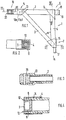
- the wheel guide member 1 essentially comprises a plurality of supports 2, 3 and 4 made of a fiber composite material, e.g. Carbon fiber, glass fiber or aramid fiber material, which are connected to one another by gluing.
- a fiber composite material e.g. Carbon fiber, glass fiber or aramid fiber material
- the supports preferably have a square cross section and, as shown in FIG. 1 using the example of a triangular link, consist of a base support 2 and two support supports 3 and 4. In the end region that meets, they are each intimately connected at a node 5, 6 and 7 .
- the node 6 is shown in Fig. 4 in more detail and shows the support beam 4, which is processed so that two parallel opposing freely projecting legs 8 and 9 form, which overlap the base beam 2 and overlap positively.
- the support bracket 3 is designed with legs 10, 11, as shown in FIG. 2. Between the supports 3, 4 and 2, 4 there is a layer 12 for adhesive bonding, e.g. made of epoxy resin.
- a force introduction element 20 is arranged at the end, which is inserted into the support 2 and can be fixed by means of the adhesive tab 13, as shown in FIG. 3.
- the pin 17 for a handlebar bearing is also embedded and fixed in the support bracket 4 .
- the base support 2 has a bore 19 at one end 18 which is led out above the support support 4 to form a further bearing on the body side.
- the carrier 2, 3 and 4 of the wheel guide member 1 can be extruded or wound. A combination of wound and extruded carriers is possible, as is the use of different fiber composite materials in one wheel guide member 1.
Landscapes
- Engineering & Computer Science (AREA)
- Mechanical Engineering (AREA)
- Moulding By Coating Moulds (AREA)
- Laminated Bodies (AREA)
Claims (7)
Applications Claiming Priority (2)
| Application Number | Priority Date | Filing Date | Title |
|---|---|---|---|
| DE19863611915 DE3611915A1 (de) | 1986-04-09 | 1986-04-09 | Radfuehrungsglied |
| DE3611915 | 1986-04-09 |
Publications (3)
| Publication Number | Publication Date |
|---|---|
| EP0241639A2 EP0241639A2 (fr) | 1987-10-21 |
| EP0241639A3 EP0241639A3 (en) | 1987-11-11 |
| EP0241639B1 true EP0241639B1 (fr) | 1989-08-09 |
Family
ID=6298303
Family Applications (1)
| Application Number | Title | Priority Date | Filing Date |
|---|---|---|---|
| EP87100667A Expired EP0241639B1 (fr) | 1986-04-09 | 1987-01-20 | Elément de support de roue |
Country Status (2)
| Country | Link |
|---|---|
| EP (1) | EP0241639B1 (fr) |
| DE (2) | DE3611915A1 (fr) |
Family Cites Families (2)
| Publication number | Priority date | Publication date | Assignee | Title |
|---|---|---|---|---|
| US2000255A (en) * | 1934-02-07 | 1935-05-07 | Lawrence B Rivard | Independent vehicle wheel suspension |
| GB1604025A (en) * | 1977-09-06 | 1981-12-02 | Hudson International Ltd Chris | Wheel mounting assemblies and suspension systems |
-
1986
- 1986-04-09 DE DE19863611915 patent/DE3611915A1/de not_active Withdrawn
-
1987
- 1987-01-20 DE DE8787100667T patent/DE3760408D1/de not_active Expired
- 1987-01-20 EP EP87100667A patent/EP0241639B1/fr not_active Expired
Also Published As
| Publication number | Publication date |
|---|---|
| EP0241639A2 (fr) | 1987-10-21 |
| EP0241639A3 (en) | 1987-11-11 |
| DE3611915A1 (de) | 1987-10-22 |
| DE3760408D1 (en) | 1989-09-14 |
Similar Documents
| Publication | Publication Date | Title |
|---|---|---|
| DE3022418C2 (de) | Rahmenförmiger Federkörper | |
| DE2657832C3 (de) | Schäkel für die Flügelaufhängung im Rumpf eines Luft- oder Raumfahrzeuges | |
| DE2757965C3 (de) | Schubübertragungselement und Verfahren zu dessen Herstellung | |
| DE2952176A1 (de) | Fuehrungslenker fuer radaufhaengungen von kraftfahrzeugen | |
| DE2521363C2 (de) | Hubschrauber-Rotorblatt | |
| DE1231967B (de) | Glasfaser-Kunstharzfeder, insbesondere fuer Kraftfahrzeuge | |
| DE3513267A1 (de) | Hydraulikbremsschlauch | |
| DE1162648B (de) | Bewehrter Hohlkoerper fuer hohe Temperaturen und erhebliche Innendruecke sowie Verfahren zu seiner Herstellung | |
| DE102014212368A1 (de) | Fahrwerkslenker aus Faserverbundwerkstoff | |
| EP2267327B1 (fr) | Fourche articulée en matières actives composites fibreuses | |
| DE102017011461A1 (de) | Verfahren zum Herstellen eines Bauteils aus einer Faserstruktur und Bauteil aus einer Faserstruktur | |
| DE1284691B (de) | Einblattfederung aus glasfaserverstaerktem Kunststoff | |
| EP0068424B1 (fr) | Elément composite de liaison, en particulier bielle ou tige, et procédé pour sa réalisation | |
| DE3612777A1 (de) | Vorderradaufhaengung | |
| DE102009043103A1 (de) | Faserverbundstruktur | |
| EP0241639B1 (fr) | Elément de support de roue | |
| DE2813178A1 (de) | Polsterungstraeger fuer eine sitzgelegenheit | |
| AT391355B (de) | Zwischenglied zum einbau in eine drehmomentuebertragende antriebsverbindung | |
| DE19814792A1 (de) | Lenkerfeder | |
| EP3162546B1 (fr) | Élément de traction en matière plastique renforcée de fibres et procédé | |
| DE2606347A1 (de) | Biegesteifer greiferwagen, insbesondere fuer offsetdruckmaschinen, und verfahren zur herstellung von biegesteifen greiferwagenstrukturen | |
| DE102014215390B3 (de) | Anordnung mit einem metallischen Anschlusselement und einem Faserverbundwerkstoff | |
| EP0409123A2 (fr) | Guide d'essieu pour bogies de voitures ferroviaires | |
| EP0967330B1 (fr) | Bar de traction pour membrure de pont | |
| DE4422579C2 (de) | Verbundbauteil als Zug-Druck-Stange für Schienenfahrzeuge |
Legal Events
| Date | Code | Title | Description |
|---|---|---|---|
| PUAI | Public reference made under article 153(3) epc to a published international application that has entered the european phase |
Free format text: ORIGINAL CODE: 0009012 |
|
| PUAL | Search report despatched |
Free format text: ORIGINAL CODE: 0009013 |
|
| AK | Designated contracting states |
Kind code of ref document: A2 Designated state(s): DE FR GB IT |
|
| AK | Designated contracting states |
Kind code of ref document: A3 Designated state(s): DE FR GB IT |
|
| 17P | Request for examination filed |
Effective date: 19880312 |
|
| 17Q | First examination report despatched |
Effective date: 19880726 |
|
| GRAA | (expected) grant |
Free format text: ORIGINAL CODE: 0009210 |
|
| AK | Designated contracting states |
Kind code of ref document: B1 Designated state(s): DE FR GB IT |
|
| ITF | It: translation for a ep patent filed | ||
| GBT | Gb: translation of ep patent filed (gb section 77(6)(a)/1977) | ||
| REF | Corresponds to: |
Ref document number: 3760408 Country of ref document: DE Date of ref document: 19890914 |
|
| ET | Fr: translation filed | ||
| PLBE | No opposition filed within time limit |
Free format text: ORIGINAL CODE: 0009261 |
|
| STAA | Information on the status of an ep patent application or granted ep patent |
Free format text: STATUS: NO OPPOSITION FILED WITHIN TIME LIMIT |
|
| 26N | No opposition filed | ||
| ITTA | It: last paid annual fee | ||
| PGFP | Annual fee paid to national office [announced via postgrant information from national office to epo] |
Ref country code: FR Payment date: 19911230 Year of fee payment: 6 |
|
| PGFP | Annual fee paid to national office [announced via postgrant information from national office to epo] |
Ref country code: GB Payment date: 19920110 Year of fee payment: 6 |
|
| PGFP | Annual fee paid to national office [announced via postgrant information from national office to epo] |
Ref country code: DE Payment date: 19920121 Year of fee payment: 6 |
|
| PG25 | Lapsed in a contracting state [announced via postgrant information from national office to epo] |
Ref country code: GB Effective date: 19930120 |
|
| GBPC | Gb: european patent ceased through non-payment of renewal fee |
Effective date: 19930120 |
|
| PG25 | Lapsed in a contracting state [announced via postgrant information from national office to epo] |
Ref country code: FR Effective date: 19930930 |
|
| PG25 | Lapsed in a contracting state [announced via postgrant information from national office to epo] |
Ref country code: DE Effective date: 19931001 |
|
| REG | Reference to a national code |
Ref country code: FR Ref legal event code: ST |
|
| PG25 | Lapsed in a contracting state [announced via postgrant information from national office to epo] |
Ref country code: IT Free format text: LAPSE BECAUSE OF NON-PAYMENT OF DUE FEES;WARNING: LAPSES OF ITALIAN PATENTS WITH EFFECTIVE DATE BEFORE 2007 MAY HAVE OCCURRED AT ANY TIME BEFORE 2007. THE CORRECT EFFECTIVE DATE MAY BE DIFFERENT FROM THE ONE RECORDED. Effective date: 20050120 |