EP0241620B1 - Hull shape of a surface-effect ship with side keels and two ways of navigating - Google Patents
Hull shape of a surface-effect ship with side keels and two ways of navigating Download PDFInfo
- Publication number
- EP0241620B1 EP0241620B1 EP86400817A EP86400817A EP0241620B1 EP 0241620 B1 EP0241620 B1 EP 0241620B1 EP 86400817 A EP86400817 A EP 86400817A EP 86400817 A EP86400817 A EP 86400817A EP 0241620 B1 EP0241620 B1 EP 0241620B1
- Authority
- EP
- European Patent Office
- Prior art keywords
- ship
- side wall
- keel
- surface effect
- set forth
- Prior art date
- Legal status (The legal status is an assumption and is not a legal conclusion. Google has not performed a legal analysis and makes no representation as to the accuracy of the status listed.)
- Expired
Links
- 230000000694 effects Effects 0.000 claims description 20
- XLYOFNOQVPJJNP-UHFFFAOYSA-N water Substances O XLYOFNOQVPJJNP-UHFFFAOYSA-N 0.000 claims description 12
- 238000007654 immersion Methods 0.000 claims description 11
- 238000007789 sealing Methods 0.000 claims description 3
- 238000006073 displacement reaction Methods 0.000 claims 2
- 230000002706 hydrostatic effect Effects 0.000 description 2
- 238000009434 installation Methods 0.000 description 2
- 239000007787 solid Substances 0.000 description 2
- 230000007423 decrease Effects 0.000 description 1
- 230000037406 food intake Effects 0.000 description 1
- 230000035515 penetration Effects 0.000 description 1
- 239000003380 propellant Substances 0.000 description 1
- 230000001105 regulatory effect Effects 0.000 description 1
- 230000007704 transition Effects 0.000 description 1
Images

Classifications
-
- B—PERFORMING OPERATIONS; TRANSPORTING
- B63—SHIPS OR OTHER WATERBORNE VESSELS; RELATED EQUIPMENT
- B63B—SHIPS OR OTHER WATERBORNE VESSELS; EQUIPMENT FOR SHIPPING
- B63B1/00—Hydrodynamic or hydrostatic features of hulls or of hydrofoils
- B63B1/02—Hydrodynamic or hydrostatic features of hulls or of hydrofoils deriving lift mainly from water displacement
- B63B1/10—Hydrodynamic or hydrostatic features of hulls or of hydrofoils deriving lift mainly from water displacement with multiple hulls
- B63B1/12—Hydrodynamic or hydrostatic features of hulls or of hydrofoils deriving lift mainly from water displacement with multiple hulls the hulls being interconnected rigidly
-
- B—PERFORMING OPERATIONS; TRANSPORTING
- B63—SHIPS OR OTHER WATERBORNE VESSELS; RELATED EQUIPMENT
- B63B—SHIPS OR OTHER WATERBORNE VESSELS; EQUIPMENT FOR SHIPPING
- B63B1/00—Hydrodynamic or hydrostatic features of hulls or of hydrofoils
- B63B1/32—Other means for varying the inherent hydrodynamic characteristics of hulls
- B63B1/34—Other means for varying the inherent hydrodynamic characteristics of hulls by reducing surface friction
- B63B1/38—Other means for varying the inherent hydrodynamic characteristics of hulls by reducing surface friction using air bubbles or air layers gas filled volumes
-
- Y—GENERAL TAGGING OF NEW TECHNOLOGICAL DEVELOPMENTS; GENERAL TAGGING OF CROSS-SECTIONAL TECHNOLOGIES SPANNING OVER SEVERAL SECTIONS OF THE IPC; TECHNICAL SUBJECTS COVERED BY FORMER USPC CROSS-REFERENCE ART COLLECTIONS [XRACs] AND DIGESTS
- Y02—TECHNOLOGIES OR APPLICATIONS FOR MITIGATION OR ADAPTATION AGAINST CLIMATE CHANGE
- Y02T—CLIMATE CHANGE MITIGATION TECHNOLOGIES RELATED TO TRANSPORTATION
- Y02T70/00—Maritime or waterways transport
- Y02T70/10—Measures concerning design or construction of watercraft hulls
Definitions
- the present invention relates to improved hull shapes for surface effect ships comprising a central structure provided with two side keels, and capable of moving either in lift mode or in Archimedean navigation mode.
- the lift is achieved by an air cushion, this cushion being delimited, below the central structure, on the one hand by the two side keels, and, on the other hand, at the bow and at the rear, by two closing devices.
- the cushion When the cushion is supplied with pressurized air, the ship is raised in a position for which only the extreme lower zone of these two pins remains in the water, the air being able to escape from the cushion only from below the two closing. In such a lifted position, the ship can reach high speeds of a Froude number greater than or equal to 1 under the effect of propellants which can be propellers or else hydrojets.
- the closures can be raised and the ship then floats on its two side keels, in Archimedean navigation.
- the present invention relates to the design of a surface effect vessel of the aforementioned type, the improved hull shapes of which ensure optimum performance both in lift mode and in Archimedean navigation mode.
- the invention therefore relates to hull forms for surface effect ships comprising a lift structure of the catamaran type provided with two side keels, joined by a central structure, suitable for sailing either in Archimedean navigation on hull, or in lift on air cushion, the side skittles delimiting with two closing devices the central air cushion for lift (C), characterized in that each of the two skittles comprises a veranda segment, an internal side wall facing the cushion (C ), and an external side wall, the veranda segment being inclined towards the outside with respect to the horizontal and being.
- the internal wall being substantially vertical at the front and at the rear and having in its upper central part a bulge, the external wall evolving from the rear towards the front from a concave curve to a solid curve, so that optimal performance is reached for the two modes of lift and archimedean navigation.
- the shapes described below cooperate effectively.
- the intersection of the veranda segment and the internal wall of each keel defines a substantially straight keel line. Therefore, the immersion depth of the inner wall, above this keel line and below the cushion line (Nc), always remains at least equal to a minimum to ensure the lateral sealing of the cushion of air.
- the vessel takes a trim such that at nominal speed, the immersion depth of the internal wall remains substantially constant from the rear to the front of this keel line. Indeed, at this speed, the wave system produced by the cushion is characterized by a constant slope from front to back.
- the wetted surface of the pins in the lift mode is limited.
- the immersion which is substantially constant and at least equal to the pins on the side of the cushion C, provides the latter with better lateral sealing conditions.
- the air from the cushion escapes, as already indicated, below the lower parts of the closing devices and not below the lines of keels.
- the shape of the surface defined by the veranda segment is close to a hyperbolic paraboloid.
- the attitude of the ship is not influenced by variations in the dynamic pressure acting on this surface. It is well known, in fact, that for such a surface the result of the forces induced by a flow applies substantially at the same point whatever the incidence.
- the building trim is not influenced by variations in dynamic pressure acting on the veranda surface, taken as the geographic location of the veranda segments.
- the position of the point of application of the resultant of the lateral forces can be controlled by suitably adjusting the survey of the veranda segment.
- the veranda segment at the rear of the ship has a sufficient transverse width at the level of which the installation of the water intakes of the hydrojets is provided.
- the vertical immersion depth of the outer wall at the rear of the vessel, above the intersection of the veranda segment and the inner wall and below the waterline (Fs), is substantially equal to the vertical immersion depth a of the internal wall, to avoid ingestion of air by the water intakes.
- the front part of the skittles is both tapered and raised to facilitate their penetration into the water.
- the form chosen for the pins is not less efficient.
- the outer wall flares at the top, especially at the front and at the rear, to form volumes ensuring a hydrostatic roll and pitch appeal.
- the inner wall is substantially vertical and planar in front of and behind the ship. Between these two ends, the upper part of the internal wall swells towards the center of the skittles, thus defining an internal bulge of the keel. These bulged volumes also make it possible to ensure, on the one hand without ballasting, a longitudinal centering of the ship, which moreover remains substantially the same in the two navigation modes, and on the other hand an additional hydrostatic booster in roll and pitch. as seen above.
- the concavity of the external wall at the rear part of the ship allows the installation of a propeller for propulsion in Archimedean navigation mode.
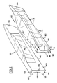
- Figure 1 illustrates the general constitution of the ship according to the invention. It essentially comprises two keels or side shells 100, joined by a central structure 200.
- the central structure 200 preferably has the form of a central box recessed in each of the two side pins 100.
- the two pins 100 cooperate with two closing devices at the front and at the rear, 310 and 320 (see FIG. 4), to delimit, between the pins 100, and below of the structure 200, a central space C, forming a lift cushion supplied by a pressurized air generator, the air being able to escape under the closing devices in the areas 310a, 320a.
- the closing devices 310 and 320 are of the lifting type, so that the ship according to the invention can move either under lift on its cushion, or in Archimedean navigation on its two keels 100.
- the problem of the invention is to optimize the shape of the side pins 100 for obtaining optimum performance both in lift mode and in Archimedean navigation mode.
- the two pins 100 arranged respectively to the right and to the left of the ship have a shape symmetrical with respect to the longitudinal vertical central plane of the ship.
- the different elements thus symmetrical of the two pins are designated by the same references.
- each keel 100 essentially comprises a veranda or bottom segment 110, an internal side wall 120, an external side wall 130, and a horizontal upper segment 140.
- a vertical flange 150 joins the segment 140 to the outer wall 130.
- the evolutionary profile of the veranda segment 110 and the evolutionary shape of the two internal and external walls 120 and 130 are particularly characteristic.
- the veranda segment 110 is rectilinear and inclined by a variable angle 8, with an initial value of about twenty degrees aft of the ship and which increases regularly to a value of around sixty degrees at the front, where the keel begins to taper.
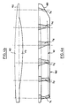
- FIG. 4a shows this development particularly well, since there are six cross sections of the keel referenced S1 to S6, from rear to front, the section S1 also being found in the rear view of FIG. 3 .
- this veranda segment 110 defines from the rear towards the front a regulated surface of the hyperbolic paraboloid type.
- the intersection of the veranda segment 110 and the internal wall 120 constitutes the keel line 160.
- This keel line is substantially rectilinear and horizontal in Archimedean navigation mode, while it is slightly inclined in lift mode.
- the intersection of the veranda segment 110 and the outer wall 130 constitutes a substantially rectilinear line 161 which rises slightly from the rear to the front relative to the keel line 160.
- the waterline in Archimedean navigation mode FA is situated approximately halfway up the keel 100.
- the central cushion C lifts the vessel and its keels, and a waterline is reached in lift mode FS, while, on the side of the internal profile 120, the cushion C pushes the water up to a NC level as shown in Figures 3 and 4.
- the shapes thus adopted for the two keels 100 are those which, as will be better understood, make it possible to optimize the behavior of the ship in each of its two navigation modes.
- the hulls 100 are very little submerged.
- the immersion height at the rear of the pins is substantially the same, a for the internal wall with respect to the cushion line NC, and for the external wall with respect to the waterline FS.
- the horizontal width L of the veranda segment 110 is relatively large, as shown, at the rear of the vessel, and decreases from the rear to the front.
- the cushion line NC remains substantially parallel to the keel line 160, which means that the immersion height of the inner wall 120 below the cushion C remains substantially constant from the rear forward of the ship, preferably not less than a.
- the front and rear closures 310 and 320 defining the lift cushion (C) are arranged in areas where the pins 100 have a substantially vertical internal wall. This arrangement allows easy vertical movement of said closures and facilitates the transition between the lift mode, where the closures are in a deployed position, and the Archimedean navigation mode for which they are raised.
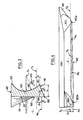
- the outer wall 130 evolves from the rear to the front, from a concave curve forming a notch, as shown in FIG. 2, to a solid shape, visible on the sections S4 and S5.
- each keel 100 has a notch 130 in which is housed the propeller 400, below the Archimedean navigation line (Fa).
- the propeller 400 is preferably liftable.
Landscapes
- Physics & Mathematics (AREA)
- Fluid Mechanics (AREA)
- Chemical & Material Sciences (AREA)
- Engineering & Computer Science (AREA)
- Combustion & Propulsion (AREA)
- Mechanical Engineering (AREA)
- Ocean & Marine Engineering (AREA)
- Vibration Prevention Devices (AREA)
Description
La présente invention concerne des formes de coque perfectionnées pour des navires à effet de surface comportant une structure centrale munie de deux quilles latérales, et susceptibles de se déplacer soit en mode de sustentation, soit en mode de navigation archimédienne.The present invention relates to improved hull shapes for surface effect ships comprising a central structure provided with two side keels, and capable of moving either in lift mode or in Archimedean navigation mode.
Dans un tel navire, la sustentation est réalisée par un coussin d'air, ce coussin étant délimité, en dessous de la structure centrale, d'une part par les deux quilles latérales, et, d'autre part, à l'avant et à l'arrière, par deux dispositifs de fermeture. Lorsque le coussin est alimenté en air sous pression, le navire se trouve soulevé dans une position pour laquelle seule la zone inférieure extrême de ces deux quilles reste dans l'eau, l'air ne pouvant échapper du coussin que par dessous les deux dispositifs de fermeture. Dans une telle position sustentée, le navire peut atteindre des vitesses élevées d'un nombre de Froude supérieur ou égal à 1 sous l'effet de propulseurs qui peuvent être des hélices ou bien des hydrojets.In such a ship, the lift is achieved by an air cushion, this cushion being delimited, below the central structure, on the one hand by the two side keels, and, on the other hand, at the bow and at the rear, by two closing devices. When the cushion is supplied with pressurized air, the ship is raised in a position for which only the extreme lower zone of these two pins remains in the water, the air being able to escape from the cushion only from below the two closing. In such a lifted position, the ship can reach high speeds of a Froude number greater than or equal to 1 under the effect of propellants which can be propellers or else hydrojets.
Lorsque le coussin d'air n'est pas alimenté, les fermetures peuvent être relevées et le navire flotte alors sur ses deux quilles latérales, en navigation archimédienne.When the air cushion is not supplied, the closures can be raised and the ship then floats on its two side keels, in Archimedean navigation.
Ce type de navire à effet de surface est bien connu; il est décrit par exemple dans les brevets FR 2 422 535, FR 1 569 807 et US 4 271 779.This type of surface effect vessel is well known; it is described for example in patents FR 2 422 535, FR 1 569 807 and US 4 271 779.
De façon générale, les navires à effet de surface du type précité ont été conçus et réalisés pour fonctionner le plus souvent en mode de sustentation sur le coussin d'air, le mode de navigation archimédienne n'étant qu'un mode de déplacement accessoire à faible vitesse.In general, surface effect vessels of the aforementioned type have been designed and produced to operate most often in the air cushion lift mode, the Archimedean navigation mode being only a mode of movement incidental to low speed.
La présente invention vise la conception d'un navire à effet de surface du type précité dont les formes de coque perfectionnées assurent des performances optimales à la fois en mode de sustentation et en mode de navigation archimédienne.The present invention relates to the design of a surface effect vessel of the aforementioned type, the improved hull shapes of which ensure optimum performance both in lift mode and in Archimedean navigation mode.
On se propose également de propulser par exemple ce navire par des hydrojets en mode de sustentation, par des hélices ou ces hydrojets en mode de navigation archimédienne. Il est apparu, de par les études et les essais conduits par le Demandeur, que la forme même des deux quilles latérales pouvait être optimisée pour les deux modes de navigation.It is also proposed to propel this vessel, for example, by hydrojets in lift mode, by propellers or these hydrojets in Archimedean navigation mode. It appeared from the studies and tests conducted by the Applicant, that the very shape of the two side keels could be optimized for the two navigation modes.
L'invention a donc pour objet des formes de coque pour navire à effet de surface comportant une structure sustentée du type catamaran munie de deux quilles latérales, réunies par une structure centrale, adapté pour naviguer soit en navigation archimédienne sur coque, soit en sustentation sur coussin d'air, les quilles latérales délimitant avec deux dispositifs de fermeture le coussin d'air central de sustentation (C), caractérisées en ce que chacune des deux quilles comporte un segment de varangue, une paroi latérale interne tournée vers le coussin (C), et une paroi latérale externe, le segment de varangue étant incliné vers l'extérieur par rapport à l'horizontale et se. relevant de l'arrière vers l'avant de la quille jusqu'à un V profond à l'extrême avant, la paroi interne étant sensiblement verticale à l'avant et à l'arrière et présentant dans sa partie centrale supérieure un renflement, la paroi externe évoluant de l'arrière vers l'avant d'une courbe concave à une courbe pleine, de telle sorte que des performances optimales soient atteintes pour les deux modes de sustentation et de navigation archimédienne.The invention therefore relates to hull forms for surface effect ships comprising a lift structure of the catamaran type provided with two side keels, joined by a central structure, suitable for sailing either in Archimedean navigation on hull, or in lift on air cushion, the side skittles delimiting with two closing devices the central air cushion for lift (C), characterized in that each of the two skittles comprises a veranda segment, an internal side wall facing the cushion (C ), and an external side wall, the veranda segment being inclined towards the outside with respect to the horizontal and being. falling from the rear towards the front of the keel to a deep V at the extreme front, the internal wall being substantially vertical at the front and at the rear and having in its upper central part a bulge, the external wall evolving from the rear towards the front from a concave curve to a solid curve, so that optimal performance is reached for the two modes of lift and archimedean navigation.
En mode de sustentation, les formes décrites ci-après coopèrent de manière efficace. En effet, selon une caractéristique de l'invention, l'intersection du segment de varangue et de la paroi interne de chaque quille définit une ligne de quille sensiblement rectiligne. De ce fait, la profondeur d'immersion de la paroi interne, au-dessus de cette ligne de quille et en dessous de la ligne de coussin (Nc), reste toujours au moins égale à un minimum pour assurer l'étanchéité latérale du coussin d'air. Le navire prend une assiette telle qu'à la vitesse nominale, la profondeur d'immersion de la paroi interne reste sensiblement constante de l'arrière à l'avant de cette ligne de quille. En effet, à cette vitesse, le système de vagues produit par le coussin est caractérisé par une pente constante de l'avant à l'arrière.In lift mode, the shapes described below cooperate effectively. Indeed, according to a characteristic of the invention, the intersection of the veranda segment and the internal wall of each keel defines a substantially straight keel line. Therefore, the immersion depth of the inner wall, above this keel line and below the cushion line (Nc), always remains at least equal to a minimum to ensure the lateral sealing of the cushion of air. The vessel takes a trim such that at nominal speed, the immersion depth of the internal wall remains substantially constant from the rear to the front of this keel line. Indeed, at this speed, the wave system produced by the cushion is characterized by a constant slope from front to back.
On remarquera en outre que la surface mouillée des quilles en mode de sustentation est limitée. L'immersion, sensiblement constante et au moins égale à a des quilles du côté du coussin C, assure à celui-ci des meilleures conditions d'étanchéité latérale. En d'autres termes, l'air du coussin s'échappe, comme on l'a déjà indiqué, en dessous des parties inférieures des dispositifs de fermeture et non en dessous des lignes de quilles.It will also be noted that the wetted surface of the pins in the lift mode is limited. The immersion, which is substantially constant and at least equal to the pins on the side of the cushion C, provides the latter with better lateral sealing conditions. In other words, the air from the cushion escapes, as already indicated, below the lower parts of the closing devices and not below the lines of keels.
Il est important de noter par ailleurs que la forme de la surface définie par le segment de varangue est voisine d'un paraboloïde hyperbolique. De ce fait, l'assiette du navire n'est pas influencée par des variations de la pression dynamique agissant sur cette surface. Il est bien connu en effet que pour une telle surface la résultante des forces induites par un écoulement s'applique sensiblement au même point quelle que soit l'incidence. Autrement dit encore, l'assiette du bâtiment n'est pas influencée par des variations de pression dynamique agissant sur la surface de varangue, prise comme le lieu géographique des segments de varangue.It is also important to note that the shape of the surface defined by the veranda segment is close to a hyperbolic paraboloid. As a result, the attitude of the ship is not influenced by variations in the dynamic pressure acting on this surface. It is well known, in fact, that for such a surface the result of the forces induced by a flow applies substantially at the same point whatever the incidence. In other words, the building trim is not influenced by variations in dynamic pressure acting on the veranda surface, taken as the geographic location of the veranda segments.
Enfin, la position du point d'application de la résultante des forces latérales (centre de dérive effectif) peut être controlée en ajustant convenablement le relevé du segment de varangue.Finally, the position of the point of application of the resultant of the lateral forces (effective center of drift) can be controlled by suitably adjusting the survey of the veranda segment.
Selon une autre caractéristique de l'invention, le segment de varangue à l'arrière du navire présente une largeur transversale suffisante au niveau de laquelle est prévue l'implantation des prises d'eau des hydrojets.According to another characteristic of the invention, the veranda segment at the rear of the ship has a sufficient transverse width at the level of which the installation of the water intakes of the hydrojets is provided.
On remarquera que la profondeur verticale d'immersion de la paroi externe à l'arrière du navire, au-dessus de l'intersection du segment de varangue et de la paroi interne et en-dessous de la ligne de flottaison (Fs), est sensiblement égale à la profondeur d'immersion verticale a de la paroi interne, pour éviter l'ingestion d'air par les prises d'eau.Note that the vertical immersion depth of the outer wall at the rear of the vessel, above the intersection of the veranda segment and the inner wall and below the waterline (Fs), is substantially equal to the vertical immersion depth a of the internal wall, to avoid ingestion of air by the water intakes.
Selon une autre caractéristique de l'invention, la partie avant des quilles est à la fois effilée et relevée pour faciliter leur pénétration dans l'eau.According to another characteristic of the invention, the front part of the skittles is both tapered and raised to facilitate their penetration into the water.
Pour ce qui est du mode de navigation archimédienne, la forme choisie pour les quilles n'est pas moins efficace. En effet, la paroi externe s'évase dans le haut, notamment à l'avant et à l'arrière, pour former des volumes assurant un appel hydrostatique en roulis et en tangage. La paroi interne est sensiblement verticale et plane à l'avant et à l'arrière du navire. Entre ces deux extrémités, la partie supérieure de la paroi interne va en se renflant vers le centre des quilles, en définissant ainsi un renflement interne de la quille. Ces volumes renflés permettent en outre d'assurer, d'une part sans ballastage un centrage longitudinal du navire, lequel reste par ailleurs sensiblement le même dans les deux modes de navigation, et d'autre part un rappel hydrostatique supplémentaire en roulis et en tangage comme on l'a vu ci-dessus.As for the Archimedean navigation mode, the form chosen for the pins is not less efficient. Indeed, the outer wall flares at the top, especially at the front and at the rear, to form volumes ensuring a hydrostatic roll and pitch appeal. The inner wall is substantially vertical and planar in front of and behind the ship. Between these two ends, the upper part of the internal wall swells towards the center of the skittles, thus defining an internal bulge of the keel. These bulged volumes also make it possible to ensure, on the one hand without ballasting, a longitudinal centering of the ship, which moreover remains substantially the same in the two navigation modes, and on the other hand an additional hydrostatic booster in roll and pitch. as seen above.
Selon une caractéristique avantageuse de l'invention, la concavité de la paroi externe à la partie arrière du navire permet l'installation d'une hélice pour la propulsion en mode de navigation archimédienne.According to an advantageous characteristic of the invention, the concavity of the external wall at the rear part of the ship allows the installation of a propeller for propulsion in Archimedean navigation mode.
Il est par ailleurs essentiel d'observer que les renflements de la quille mentionnée ci-dessus permettent d'assurer la portance du navire en mode de navigation archimédienne sans abaissement trop considérable du navire par rapport à la surface de l'eau. En d'autres termes, ces volumes permettent de diminuer la distance verticale entre la ligne de flottaison archimédienne (Fa) et la ligne de flottaison en sustentation (Fs). Une telle caractéristique sert à limiter les impacts des vagues sur la structure centrale.It is also essential to observe that the bulges of the keel mentioned above make it possible to ensure the lift of the vessel in Archimedean navigation mode without too considerable lowering of the vessel relative to the surface of the water. In other words, these volumes make it possible to reduce the vertical distance between the Archimedean water line (Fa) and the floating water line (Fs). Such a characteristic serves to limit the impacts of waves on the central structure.
Enfin, les volumes renflés permettent évidemment de dégager des espaces utiles à l'aménagement des quilles.Finally, the bulged volumes obviously allow to clear spaces useful for the arrangement of the skittles.
L'ensemble des caractéristiques précitées coopère pour donner au navire selon l'invention un comportement optimisé pour les deux modes de navigation, la navigation archimédienne, en particulier, devenant utilisable en tant que telle pour avoir une grande autonomie.All of the aforementioned characteristics cooperate to give the ship according to the invention an optimized behavior for the two navigation modes, Archimedean navigation, in particular, becoming usable as such to have a great autonomy.
D'autres caractéristiques et avantages de l'invention apparaîtront de la description qui va suivre, en se référant aux dessins annexés, qui représentent une forme de réalisation préférentielle de l'invention.Other characteristics and advantages of the invention will emerge from the description which follows, with reference to the appended drawings, which represent a preferred embodiment of the invention.
Sur ces dessins:
- - la figure 1 représente une vue en perspective de trois quarts arrière d'un navire à effet de surface selon la présente invention;
- - la figure 2 représente en perspective dans une vue analogue à la précédente les deux quilles latérales de ce navire en vis-à-vis, toutes les autres parties du navire ayant été supprimées;
- - la figure 3 est une vue de bout de l'extrémité arrière de la quille de droite;
- - la figure 4 représente une vue de côté schématique du navire selon l'invention;
- - la figure 4a représente une vue de côté de la quille de droite avec différentes sections transversales échelonnées, pour bien montrer leur évolution de l'arrière vers l'avant du navire;
- - la figure 4b représente une vue de dessus schématique de la quille de gauche.
- - Figure 1 shows a perspective view of three rear quarters of a surface effect ship according to the present invention;
- - Figure 2 shows in perspective in a view similar to the previous one the two side pins of this ship vis-à-vis, all the other parts of the ship having been deleted;
- - Figure 3 is an end view of the rear end of the right keel;
- - Figure 4 shows a schematic side view of the ship according to the invention;
- - Figure 4a shows a side view of the right keel with different staggered cross sections, to clearly show their evolution from the rear to the front of the ship;
- - Figure 4b shows a schematic top view of the left keel.
La figure 1 illustre la constitution générale du navire selon l'invention. Il comporte essentiellement deux quilles ou coques latérales 100, réunies par une structure centrale 200.Figure 1 illustrates the general constitution of the ship according to the invention. It essentially comprises two keels or
La structure centrale 200 a de préference la forme d'un caisson central encastré dans chacune des deux quilles latérales 100.The
Bien qu'une telle structure ne fasse pas partie de la présente invention, on pourra se reporter à la demande de brevet français intitulée "Structure de navire à effet de surface à quilles latérales" déposée ce même jour et qui donne le détail d'une telle structure centrale.Although such a structure is not part of the present invention, reference may be made to the French patent application entitled "Structure of surface effect ship with side keels" filed on the same day and which gives details of a such central structure.
D'une manière connue en elle-même, les deux quilles 100 coopèrent avec deux dispositifs de fermeture à l'avant et à l'arrière, 310 et 320 (voir figure 4), pour délimiter, entre les quilles 100, et en dessous de la structure 200, un espace central C, formant coussin de sustentation alimenté par un générateur d'air sous pression, l'air pouvant s'échapper sous les dispositifs de fermeture dans les zones 310a, 320a.In a manner known in itself, the two
Les dispositifs de fermeture 310 et 320 sont du type relevable, de telle sorte que le navire selon l'invention peut se déplacer soit en sustentation sur son coussin, soit en navigation archimédienne sur ses deux quilles 100.The
En ce qui concerne les dispositifs de relevage, on pourra se reporter aux demandes de brevet français citées ci-dessous, toutes deux au nom du Demandeur:
- - "Navire à quilles latérales à effet de surface muni d'une fermeture avant perfectionnée de coussin de sustentation" N° 8 417 168, pour la fermeture avant.
- - "Navire à effet de surface à quilles latérales comportant des moyens de sustentation perfectionnés" N° 8 417 169, pour la fermeture arrière.
- - "Vessel with side skittles with surface effect fitted with an improved front closure of lift cushion" N ° 8 417 168, for the front closure.
- - "Surface effect vessel with side keels including improved lifting means" N ° 8 417 169, for aft closure.
Comme on l'a exposé, le problème de l'invention est d'optimiser la forme des quilles latérales 100 pour l'obtention de performances optimales aussi bien en mode de sustentation qu'en mode de navigation archimédienne.As has been explained, the problem of the invention is to optimize the shape of the side pins 100 for obtaining optimum performance both in lift mode and in Archimedean navigation mode.
Les deux quilles 100 disposées respectivement à droite et à gauche du navire ont une forme symétrique par rapport au plan central vertical longitudinal du navire. Les différents éléments ainsi symétriques des deux quilles sont désignés par les mêmes références.The two
De façon générale, chaque quille 100 comporte essentiellement un segment de varangue ou de fond 110, une paroi latérale interne 120, une paroi latérale externe 130, et un segment supérieur horizontal 140. Dans l'exemple représenté, un rebord vertical 150 réunit le segment 140 à la paroi externe 130.Generally, each
Sont particulièrement caractéristiques le profil évolutif du segment de varangue 110 et la forme évolutive des deux parois interne et externe 120 et 130.The evolutionary profile of the
Comme on le voit notamment sur les figures 2, 3 et 4a, le segment de varangue 110 est rectiligne et incliné d'un angle 8 variable, d'une valeur initiale d'une vingtaine de degrés à l'arrière du navire et qui croît régulièrement jusqu'à une valeur d'une soixantaine de degrés à la partie avant, là où la quille commence à s'effiler. La figure 4a montre particulièrement bien cette évolution, puisqu'on y voit six sections transversales de la quille référencées S1 à S6, de l'arrière à l'avant, la section S1 se retrouvant d'ailleurs sur la vue arrière de la figure 3.As can be seen in particular in FIGS. 2, 3 and 4a, the
Avec une telle variation, ce segment de varangue 110, définit de l'arrière vers l'avant une surface réglée du type paraboloïde hyperbolique.With such a variation, this
L'intersection du segment de varangue 110 et de la paroi interne 120 constitue la ligne de quille 160. Cette ligne de quille est sensiblement rectiligne et horizontale en mode de navigation archimédienne, alors qu'elle est légèrement inclinée en mode de sustentation. L'intersection du segment de varangue 110 et de la paroi externe 130 constitue une ligne sensiblement rectiligne 161 qui se relève légèrement de l'arrière vers l'avant par rapport à la ligne de quille 160.The intersection of the
Les formes de coques ci-dessus étant bien définies, il faut y ajouter, pour une bonne compréhension de l'invention, les éléments fonctionnels suivants.The above forms of shells being well defined, it is necessary to add thereto, for a good understanding of the invention, the following functional elements.
Comme représenté particulièrement à la figure 3, la ligne de flottaison en mode de navigation archimédienne FA, se situe à peu près à mi-hauteur de la quille 100.As shown particularly in FIG. 3, the waterline in Archimedean navigation mode FA, is situated approximately halfway up the
En mode de sustentation, le coussin central C soulève le navire et ses quilles, et on atteint ainsi une ligne de flottaison en mode sustenté FS, alors que, du côté du profil interne 120, le coussin C repousse l'eau jusqu'à un niveau NC comme représenté sur les figures 3 et 4.In lift mode, the central cushion C lifts the vessel and its keels, and a waterline is reached in lift mode FS, while, on the side of the
Les formes ainsi adoptées pour les deux quilles 100 sont celles qui, comme on va mieux le comprendre, permettent d'optimiser le comportement du navire dans chacun de ses deux modes de navigation.The shapes thus adopted for the two
En mode de sustentation, les coques 100 sont très peu immergées. Comme on le voit sur la figure 3, la hauteur d'immersion à l'arrière des quilles est sensiblement la même, soit a pour la paroi interne par rapport à la ligne de coussin NC, et pour la paroi externe, par rapport à la ligne de flottaison FS. La largeur horizontale L du segment de varangue 110 est relativement grande, comme représenté, à l'arrière du navire, et diminue de l'arrière vers l'avant. Comme on le voit sur la figure 4, la ligne de coussin NC reste sensiblement parallèle à la ligne de quille 160, ce qui signifie que la hauteur d'immersion de la paroi interne 120 en dessous du coussin C reste sensiblement constante de l'arrière vers l'avant du navire, en n'étant pas de préférence inférieure à a.In the lift mode, the
De telles formes de quille et de telles conditions d'immersion pour le mode de sustentation entraînent des avantages certains.Such keel shapes and such immersion conditions for the mode of lift bring certain advantages.
Tout d'abord, dans la région la plus immergée, à l'arrière des quilles, en dessous de la ligne de flottaison FS, on peut installer des propulseurs à jets d'eau à circuit court de propulsion, ou hydrojets, simplement référencés 180 sur les figures 2 et 3. Les prises d'eau alimentant ces hydrojets sont situées en dessous de la surface FS.First of all, in the most submerged region, behind the keels, below the waterline FS, we can install short-circuit water jet propellers, or hydrojets, simply referenced 180 in Figures 2 and 3. The water intakes supplying these hydrojets are located below the FS surface.
Comme on l'a déjà vu, les fermetures avant et arrière 310 et 320 définissant le coussin de sustentation (C) sont disposées dans des zones où les quilles 100 ont une paroi interne sensiblement verticale. Cet agencement autorise un débattement vertical aisé desdites fermetures et facilite la transition entre le mode sustenté, où les fermetures sont dans une position déployée, et le mode de navigation archimédienne pour lequel elles sont relevées.As we have already seen, the front and
La paroi externe 130 évolue de l'arrière à l'avant, depuis une courbe concave formant échancrure, comme représenté à la figure 2 jusqu'à une forme pleine, visible sur les sections S4 et S5.The
Dans la partie arrière du navire, la paroi externe 130 de chaque quille 100 présente une échancrure 130 dans laquelle vient se loger l'hélice de propulsion 400, en-desous de la ligne de navigation archimédienne (Fa).In the rear part of the ship, the
Bien que cette caractéristique ne concerne pas la présente invention, l'hélice 400 est de préférence relevable. A cet égard, l'on peut se reporter à la demande de brevet français au nom du Demandeur N° 8 415 755 intitulée "Système de relevage d'une hélice de propulsion marine pour navire à effet de surface à quilles latérales".Although this characteristic does not relate to the present invention, the
L'évolution des formes de quilles de l'arrière vers l'avant permet d'obtenir le meilleur compromis autorisant à la fois de hautes performances en mode de sustentation et en mode de navigation archimédienne. A titre d'exemple, pour un navire du type précité de 80 mètres de long, on atteint une vitesse de l'ordre de 50 noeuds en mode de sustentation et propulsion par hydrojets, et de 20 noeuds en mode de navigation archimédienne et propulsion par hélices.The evolution of the bowling shapes from back to front makes it possible to obtain the best compromise allowing both high performance in lift mode and in Archimedean navigation mode. By way of example, for a ship of the aforementioned type of 80 meters in length, a speed of the order of 50 knots is reached in the mode of lift and propulsion by hydrojets, and of 20 knots in the mode of archimedean navigation and propulsion by propellers.
Claims (9)
Priority Applications (3)
| Application Number | Priority Date | Filing Date | Title |
|---|---|---|---|
| FR8505312A FR2579951A1 (en) | 1985-04-09 | 1985-04-09 | Hull forms for surface-effect ship with lateral keels and two modes of sailing |
| EP86400817A EP0241620B1 (en) | 1986-04-16 | 1986-04-16 | Hull shape of a surface-effect ship with side keels and two ways of navigating |
| DE8686400817T DE3662368D1 (en) | 1986-04-16 | 1986-04-16 | Hull shape of a surface-effect ship with side keels and two ways of navigating |
Applications Claiming Priority (1)
| Application Number | Priority Date | Filing Date | Title |
|---|---|---|---|
| EP86400817A EP0241620B1 (en) | 1986-04-16 | 1986-04-16 | Hull shape of a surface-effect ship with side keels and two ways of navigating |
Publications (2)
| Publication Number | Publication Date |
|---|---|
| EP0241620A1 EP0241620A1 (en) | 1987-10-21 |
| EP0241620B1 true EP0241620B1 (en) | 1989-03-15 |
Family
ID=8196296
Family Applications (1)
| Application Number | Title | Priority Date | Filing Date |
|---|---|---|---|
| EP86400817A Expired EP0241620B1 (en) | 1985-04-09 | 1986-04-16 | Hull shape of a surface-effect ship with side keels and two ways of navigating |
Country Status (3)
| Country | Link |
|---|---|
| EP (1) | EP0241620B1 (en) |
| DE (1) | DE3662368D1 (en) |
| FR (1) | FR2579951A1 (en) |
Families Citing this family (3)
| Publication number | Priority date | Publication date | Assignee | Title |
|---|---|---|---|---|
| WO1993007046A1 (en) * | 1991-10-07 | 1993-04-15 | Nasec Sa | Naturally-aspirated surface-effect watercraft |
| FR2762578B1 (en) * | 1997-04-29 | 1999-06-04 | France Etat | AUTONOMOUS CONTAINER SHIP |
| FR2762579B1 (en) | 1997-04-29 | 1999-06-04 | France Etat | SELF-CONTAINED CONTAINER SHIP HAVING A PROPULSIVE ASSEMBLY |
Family Cites Families (5)
| Publication number | Priority date | Publication date | Assignee | Title |
|---|---|---|---|---|
| FR918390A (en) * | 1945-02-27 | 1947-02-06 | Boat | |
| GB1210973A (en) * | 1968-03-05 | 1970-11-04 | Hovermarine Ltd | Improvements in or relating to marine craft |
| US3847103A (en) * | 1972-05-04 | 1974-11-12 | R Takeuchi | Split hull design for boats |
| GB1453184A (en) * | 1972-08-01 | 1976-10-20 | Corson P F R | Air-cushion craft |
| US4506618A (en) * | 1982-11-12 | 1985-03-26 | Textron, Inc. | Propeller and keel arrangement for surface effect ships |
-
1985
- 1985-04-09 FR FR8505312A patent/FR2579951A1/en active Granted
-
1986
- 1986-04-16 EP EP86400817A patent/EP0241620B1/en not_active Expired
- 1986-04-16 DE DE8686400817T patent/DE3662368D1/en not_active Expired
Also Published As
| Publication number | Publication date |
|---|---|
| EP0241620A1 (en) | 1987-10-21 |
| DE3662368D1 (en) | 1989-04-20 |
| FR2579951A1 (en) | 1986-10-10 |
| FR2579951B1 (en) | 1987-05-22 |
Similar Documents
| Publication | Publication Date | Title |
|---|---|---|
| CA1265175A (en) | Hull shapes for ground effect vessels with lateral keels, adapted for dual mode navigation | |
| EP0991562B1 (en) | Monohull with rear stabilisers for high speed ship | |
| FR2933372A1 (en) | SHIP WHEREIN THE DOLL IS EQUIPPED WITH SUCH DEVICE FOR DEFINING WATER FLOW | |
| EP0527897B1 (en) | Multi-hull sailing vessel | |
| FR2499934A1 (en) | FLOATING AND INSUBMERSIBLE NAUTICAL EQUIPMENT | |
| FR3025176A1 (en) | REMOVABLE PORTABLE FENDER | |
| EP0241620B1 (en) | Hull shape of a surface-effect ship with side keels and two ways of navigating | |
| EP3329068A2 (en) | The invention relates to dynamic artificial wave installations for surfing | |
| EP0073214B1 (en) | Self stable trimaran | |
| EP0105819A1 (en) | Fast boat | |
| FR2837782A1 (en) | TRIMARAN TYPE HIGH SPEED SHIP HULL | |
| EP1910161B1 (en) | High-speed multihull boat | |
| FR2532907A1 (en) | Lifeboat | |
| FR2503083A2 (en) | PROPULSION AND STEERING DEVICE OF A VESSEL | |
| EP0012098A1 (en) | Ship of the catamaran type with a central stem | |
| FR2650550A1 (en) | Boat hull with truncated tunnel | |
| FR2805241A1 (en) | Specialist vessel designed to pick up floating material at the bow includes high maneuverability steering systems, heated scooping equipment and temporary on-board storage | |
| CH495248A (en) | Set for the aquatic transport of goods | |
| EP0789657B1 (en) | Roll-stabilised surface-effect vessel | |
| WO2023247878A1 (en) | Wind-driven ship with an extension and a fender | |
| FR2594783A1 (en) | Catamaran for fishing or transport | |
| FR2707587A1 (en) | Roll-stabilised surface-effect ship | |
| FR3087746A1 (en) | Vessel comprising longitudinal reinforcement arches | |
| GB2027643A (en) | Marine Craft | |
| FR2615474A1 (en) | Aerodynamic flaps for motorised multi-hull boats |
Legal Events
| Date | Code | Title | Description |
|---|---|---|---|
| PUAI | Public reference made under article 153(3) epc to a published international application that has entered the european phase |
Free format text: ORIGINAL CODE: 0009012 |
|
| 17P | Request for examination filed |
Effective date: 19860515 |
|
| AK | Designated contracting states |
Kind code of ref document: A1 Designated state(s): DE GB IT NL SE |
|
| 17Q | First examination report despatched |
Effective date: 19880721 |
|
| GRAA | (expected) grant |
Free format text: ORIGINAL CODE: 0009210 |
|
| AK | Designated contracting states |
Kind code of ref document: B1 Designated state(s): DE GB IT NL SE |
|
| ITF | It: translation for a ep patent filed | ||
| REF | Corresponds to: |
Ref document number: 3662368 Country of ref document: DE Date of ref document: 19890420 |
|
| GBT | Gb: translation of ep patent filed (gb section 77(6)(a)/1977) | ||
| PLBE | No opposition filed within time limit |
Free format text: ORIGINAL CODE: 0009261 |
|
| STAA | Information on the status of an ep patent application or granted ep patent |
Free format text: STATUS: NO OPPOSITION FILED WITHIN TIME LIMIT |
|
| 26N | No opposition filed | ||
| ITTA | It: last paid annual fee | ||
| EAL | Se: european patent in force in sweden |
Ref document number: 86400817.2 |
|
| PGFP | Annual fee paid to national office [announced via postgrant information from national office to epo] |
Ref country code: SE Payment date: 19960329 Year of fee payment: 11 |
|
| PGFP | Annual fee paid to national office [announced via postgrant information from national office to epo] |
Ref country code: GB Payment date: 19960404 Year of fee payment: 11 |
|
| PGFP | Annual fee paid to national office [announced via postgrant information from national office to epo] |
Ref country code: NL Payment date: 19960430 Year of fee payment: 11 |
|
| PGFP | Annual fee paid to national office [announced via postgrant information from national office to epo] |
Ref country code: DE Payment date: 19960626 Year of fee payment: 11 |
|
| PG25 | Lapsed in a contracting state [announced via postgrant information from national office to epo] |
Ref country code: GB Effective date: 19970416 |
|
| PG25 | Lapsed in a contracting state [announced via postgrant information from national office to epo] |
Ref country code: SE Effective date: 19970417 |
|
| PG25 | Lapsed in a contracting state [announced via postgrant information from national office to epo] |
Ref country code: NL Effective date: 19971101 |
|
| GBPC | Gb: european patent ceased through non-payment of renewal fee |
Effective date: 19970416 |
|
| PG25 | Lapsed in a contracting state [announced via postgrant information from national office to epo] |
Ref country code: DE Free format text: LAPSE BECAUSE OF NON-PAYMENT OF DUE FEES Effective date: 19980101 |
|
| NLV4 | Nl: lapsed or anulled due to non-payment of the annual fee |
Effective date: 19971101 |
|
| EUG | Se: european patent has lapsed |
Ref document number: 86400817.2 |
|
| PG25 | Lapsed in a contracting state [announced via postgrant information from national office to epo] |
Ref country code: IT Free format text: LAPSE BECAUSE OF NON-PAYMENT OF DUE FEES;WARNING: LAPSES OF ITALIAN PATENTS WITH EFFECTIVE DATE BEFORE 2007 MAY HAVE OCCURRED AT ANY TIME BEFORE 2007. THE CORRECT EFFECTIVE DATE MAY BE DIFFERENT FROM THE ONE RECORDED. Effective date: 20050416 |