EP0241580A2 - Apparatus for determining amount of soluble gas contained in molten metal - Google Patents
Apparatus for determining amount of soluble gas contained in molten metal Download PDFInfo
- Publication number
- EP0241580A2 EP0241580A2 EP86112477A EP86112477A EP0241580A2 EP 0241580 A2 EP0241580 A2 EP 0241580A2 EP 86112477 A EP86112477 A EP 86112477A EP 86112477 A EP86112477 A EP 86112477A EP 0241580 A2 EP0241580 A2 EP 0241580A2
- Authority
- EP
- European Patent Office
- Prior art keywords
- cell
- gas
- amplifier
- molten metal
- carrier gas
- Prior art date
- Legal status (The legal status is an assumption and is not a legal conclusion. Google has not performed a legal analysis and makes no representation as to the accuracy of the status listed.)
- Withdrawn
Links
Images
Classifications
-
- G—PHYSICS
- G01—MEASURING; TESTING
- G01N—INVESTIGATING OR ANALYSING MATERIALS BY DETERMINING THEIR CHEMICAL OR PHYSICAL PROPERTIES
- G01N27/00—Investigating or analysing materials by the use of electric, electrochemical, or magnetic means
- G01N27/02—Investigating or analysing materials by the use of electric, electrochemical, or magnetic means by investigating impedance
- G01N27/04—Investigating or analysing materials by the use of electric, electrochemical, or magnetic means by investigating impedance by investigating resistance
- G01N27/14—Investigating or analysing materials by the use of electric, electrochemical, or magnetic means by investigating impedance by investigating resistance of an electrically-heated body in dependence upon change of temperature
- G01N27/18—Investigating or analysing materials by the use of electric, electrochemical, or magnetic means by investigating impedance by investigating resistance of an electrically-heated body in dependence upon change of temperature caused by changes in the thermal conductivity of a surrounding material to be tested
- G01N27/185—Investigating or analysing materials by the use of electric, electrochemical, or magnetic means by investigating impedance by investigating resistance of an electrically-heated body in dependence upon change of temperature caused by changes in the thermal conductivity of a surrounding material to be tested using a catharometer
Definitions
- the present invention is related generally to apparatus for determining the amount of soluble gas contained in a body of molten metal, and particularly to an electrical circuit arrangement that greatly simplifies and reduces the cost of the circuit arrangement presently employed by such apparatus.
- the circuit arrangement of the invention considerably reduces the consumption of power.
- Each of the cells includes a structure for housing the wire, one of which is opened to atmosphere, such that the cell receives a relatively constant amount of hydrogen gas and therefore serves as a reference cell.
- the other cell is a measuring cell and has its housing connected to receive a carrier gas containing molecules of a second, hydrogen gas, for example, that is soluble in molten metal.
- the hydrogen constant of the reference cell is balanced against the carrier gas in the measuring cell before the carrier gas receives molecules of the hydrogen gas to obtain a zero value indicative of such balance.
- This balancing requires identical platinum wire elements which are generally handwound on inert insulating cores. This winding process is a tedious, time consuming process which ultimately does not guarantee that the matching process will be correct.
- a resistance bridge circuit which includes the platinum wires, requires, i.e., consumes, a certain amount of electrical energy.
- Apparatus employed for determining soluble gas content are portable, as they must be moved from furnace to furnace to make the measurements discussed above. For this reason such apparatus are battery powered. Hence, the importance of minimum power consumption.
- the present invention involves the discovery that the reference catharometer cell can be eliminated along with the bridge circuit by use of an inexpensive solid-state constant current source (as opposed to a constant voltage source) to provide the reference for comparison with the electrical resistance of a single catharometer cell.
- the constant current source is connected in electrical series between a battery and the single cell. Pure carrier gas is introduced into the cell (and system) to purge the same, as discussed in the Warchol et al application. The presence of the carrier stabilizes the electrical resistance of the wire. This stabilizes the flow of electrical current through the wire and the resulting drop in the voltage developed across the wire.
- An operational amplifier is connected across the catharometer wire to provide a voltage buffer with gain, that increases the sensitivity of the reading provided by the catharometer.
- a zero offset voltage reference is provided that allows adjustment of the amplifier output. In this manner amplifier output can be nulled to zero volts or another predetermined voltage value.
- the carrier gas is circulated through the body of molten metal such that it entrains molecules of the gas (hydrogen) dissolved in the molten metal.
- the two gases are then directed to the cell, which cools the platinum wire and decreases its electrical resistance, i.e., hydrogen has a greater ability to remove heat from the wire of the cell than that of the carrier gas, which may be nitrogen, for example.
- the voltage drop across the wire is now changed from that existing across the amplifier; the voltage drop across the wire being proportional to the hydrogen content of the carrier gas.
- the amplifier now provides an output that is a reading of the amount of hydrogen in the body of molten metal.
- a catharometer cell l0 is shown schematically, and is shown connected between ground and a constant current source l2.
- the cell includes a single coil of platinum wire (not shown) that serves to measure the amount of gas content in a body of molten metal (not shown).
- the wire is contained in a housing (not shown) to receive the gas content. It is believed unnecessary to show further details of the apparatus, as such are depicted and described in the above references to Ransley and Warchol et al.
- Constant current source l2 is connected in electrical series between cell l0 and a direct current (battery) source l4.
- the constant current source is preferably a compact, low current drain, solid-state device, for example, such as the LM3l7 available from National Semiconductor of Santa Clara, California, though other devices are available and can be used.
- the LM3l7 is a three terminal (pin) adjustable voltage regulator that is ordinarily used, as the name indicates, to regulate voltage.
- the device can be made to regulate current and thereby provide a constant supply of current. This is accomplished by connecting a resistor l5 between an output pin of the device and an "adjustable" pin of the device.
- the adjustable pin and resistor gives the device the flexibility employed here.
- a twelve ohm resistor for example, provides a constant direct current (DC) output from device l2 of l04 milliamps. Any call for a change in current from l2 is compensated for by the device, the change appearing between the input and output terminals as a change in voltage, as opposed to appearing across resistor l5.
- a l04 milliamp supply is suitable for the purposes of the present invention.
- circuit l6 Connected across cell l0 is "balancing" circuit l6.
- Circuit l6 is employed to balance the current flow through cell l0, when carrier gas alone is present in the cell, against the constant current supply provided by current source l2. In this manner, when the carrier gas is circulated in the molten metal, and hydrogen gas is entrained in the carrier gas, the voltage change developed across cell l0 will be proportional to the amount of hydrogen in the carrier gas and thus in the molten metal.
- circuit l6 is that of an operational amplifier, designated l8, though other circuit means can be employed.
- An amplifier that has been found suitable for the purposes of the invention is National's eight pin LMl0.
- the voltage drop across cell l0 is shown directly coupled to the negative input (pin 2) of amplifier l8 via a two thousand ohm resistor 20.
- the gain of the amplifier is fixed by an external feedback resistor 22 connected between pin 2 and 6, which is a l0K ohm resistor if the LMl0 is employed in the manner shown in the drawing.
- the LMl0 is a combination of two operational amplifiers with pins l and 8 being the terminals of the second amplifier. Pins 2, 3, and 6 are those of the first amplifier.
- the positive terminal (pin 3) of the first amplifier is connected to the output (pin l) of the second amplifier via a l0K resistor 24 such that the positive input to the first amplifier is the output of the second amplifier. In this manner, the first amplifier is under the control of the second amplifier, as explained in detail hereinafter.
- Pin 8 is the input terminal of the second amplifier.
- the gain of the second amplifier is set by a 5K ohm adjustable feedback resistance 26 and a fixed, 8.2K ohm feedback resistor 28.
- the input impedance for the second amplifier is established by l.5K ohm resistor 30 when using (again) the LMl0 amplifier.
- the output voltage (pin 6) of amplifier l8 is developed across an adjustable lK ohm resistance 32 and a fixed l.5K resistor 34, 34 providing an appropriate range of adjustment for 32.
- the apparatus and circuit functions in the following manner.
- the catharometer l0 along with a probe and associated plumbing, as described in the above patent references, is purged with an inert carrier gas.
- Current flow through cell l0 stabilizes, as the electrical resistance of the platinum wire coil of l0 stabilizes in the process of the gas withdrawing heat from the coil; it will be recalled that the coil of cell l0 is heated by current flow from battery l4 and current source l2.
- the purge-carrier gas is next directed to the body of molten metal.
- the carrier gas acquires molecules of the gas content of the molten metal and carries the same to cell l0. This process continues until the pressure between the two gases reaches equilibrium.
- the presence of the gas content (hydrogen, for example) in cell l0 changes the resistance of the platinum wire by cooling the same, as the gas content (hydrogen) has a greater capacity for removing heat from the wire than the carrier gas.
- the voltage drop across cell l0 is now changed from that existing across circuit l6 such that l6 now outputs a signal at pin 6 of l8 that is a reading of the proportionality of the gas content to the carrier gas. This reading, as explained in the Warchol application, is used to determine the gas content of the body of molten metal.
- the constant current provided by source l2 assures a voltage drop across cell l0 that changes only in response to the precise amount of gas content in cell l0.
- circuit l6 is provided with a "span adjustment" in the presence of adjustable resistance 32.
- a known, predetermined amount of gas content say 6 percent hydrogen, is combined with the carrier gas, such that the remainder (94 percent) is carrier gas.
- circuit l6 is provided with a desired known output at pin 6. This adjustment calibrates the circuit of l6 for the particular platinum wire that will be used to determine the amount of gas content in bodies of molten metal.
Landscapes
- Chemical & Material Sciences (AREA)
- Chemical Kinetics & Catalysis (AREA)
- Electrochemistry (AREA)
- Physics & Mathematics (AREA)
- Health & Medical Sciences (AREA)
- Life Sciences & Earth Sciences (AREA)
- Analytical Chemistry (AREA)
- Biochemistry (AREA)
- General Health & Medical Sciences (AREA)
- General Physics & Mathematics (AREA)
- Immunology (AREA)
- Pathology (AREA)
- Investigating Or Analyzing Materials By The Use Of Electric Means (AREA)
- Investigating And Analyzing Materials By Characteristic Methods (AREA)
Abstract
Description
- The present invention is related generally to apparatus for determining the amount of soluble gas contained in a body of molten metal, and particularly to an electrical circuit arrangement that greatly simplifies and reduces the cost of the circuit arrangement presently employed by such apparatus. In addition, the circuit arrangement of the invention considerably reduces the consumption of power.
- U.S.
Patent 2,86l,450 to Ransley and pending U.S. Patent application Serial Number 763,290 to Warchol et al, (Warchol being the inventor of the present invention), disclose apparatus employed to measure the amounts of soluble gases found in molten aluminum and aluminum alloys, hydrogen being the most important of these gases. The disclosures of Ransley and Warchol et al are incorporated herein by reference. Both disclosures employ a catharometer comprised of two cells, with each cell including a fine platinum wire coil electrically connected in two legs of an electrical resistance bridge circuit. A small electrical potential is applied across the bridge and cells to heat the platinum wires. Each of the cells includes a structure for housing the wire, one of which is opened to atmosphere, such that the cell receives a relatively constant amount of hydrogen gas and therefore serves as a reference cell. The other cell is a measuring cell and has its housing connected to receive a carrier gas containing molecules of a second, hydrogen gas, for example, that is soluble in molten metal. The hydrogen constant of the reference cell is balanced against the carrier gas in the measuring cell before the carrier gas receives molecules of the hydrogen gas to obtain a zero value indicative of such balance. This balancing requires identical platinum wire elements which are generally handwound on inert insulating cores. This winding process is a tedious, time consuming process which ultimately does not guarantee that the matching process will be correct. - In addition, it can be appreciated that a resistance bridge circuit, which includes the platinum wires, requires, i.e., consumes, a certain amount of electrical energy. Apparatus employed for determining soluble gas content are portable, as they must be moved from furnace to furnace to make the measurements discussed above. For this reason such apparatus are battery powered. Hence, the importance of minimum power consumption.
- The present invention involves the discovery that the reference catharometer cell can be eliminated along with the bridge circuit by use of an inexpensive solid-state constant current source (as opposed to a constant voltage source) to provide the reference for comparison with the electrical resistance of a single catharometer cell. The constant current source is connected in electrical series between a battery and the single cell. Pure carrier gas is introduced into the cell (and system) to purge the same, as discussed in the Warchol et al application. The presence of the carrier stabilizes the electrical resistance of the wire. This stabilizes the flow of electrical current through the wire and the resulting drop in the voltage developed across the wire. An operational amplifier is connected across the catharometer wire to provide a voltage buffer with gain, that increases the sensitivity of the reading provided by the catharometer. A zero offset voltage reference is provided that allows adjustment of the amplifier output. In this manner amplifier output can be nulled to zero volts or another predetermined voltage value.
- The carrier gas is circulated through the body of molten metal such that it entrains molecules of the gas (hydrogen) dissolved in the molten metal. The two gases are then directed to the cell, which cools the platinum wire and decreases its electrical resistance, i.e., hydrogen has a greater ability to remove heat from the wire of the cell than that of the carrier gas, which may be nitrogen, for example. The voltage drop across the wire is now changed from that existing across the amplifier; the voltage drop across the wire being proportional to the hydrogen content of the carrier gas. The amplifier now provides an output that is a reading of the amount of hydrogen in the body of molten metal.
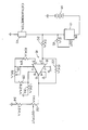
- The invention, along with its objectives and advantages, will be best understood from consideration of the following detailed description and accompanying drawing, the sole figure of which is a schematic representation of the circuit of the invention.
- Referring now to the drawing, a catharometer cell l0 is shown schematically, and is shown connected between ground and a constant current source l2. The cell, as discussed above, includes a single coil of platinum wire (not shown) that serves to measure the amount of gas content in a body of molten metal (not shown). Hence, the wire is contained in a housing (not shown) to receive the gas content. It is believed unnecessary to show further details of the apparatus, as such are depicted and described in the above references to Ransley and Warchol et al.
- Constant current source l2 is connected in electrical series between cell l0 and a direct current (battery) source l4. The constant current source is preferably a compact, low current drain, solid-state device, for example, such as the LM3l7 available from National Semiconductor of Santa Clara, California, though other devices are available and can be used. The LM3l7 is a three terminal (pin) adjustable voltage regulator that is ordinarily used, as the name indicates, to regulate voltage. The device, however, can be made to regulate current and thereby provide a constant supply of current. This is accomplished by connecting a resistor l5 between an output pin of the device and an "adjustable" pin of the device. The adjustable pin and resistor gives the device the flexibility employed here. A twelve ohm resistor, for example, provides a constant direct current (DC) output from device l2 of l04 milliamps. Any call for a change in current from l2 is compensated for by the device, the change appearing between the input and output terminals as a change in voltage, as opposed to appearing across resistor l5. A l04 milliamp supply is suitable for the purposes of the present invention.
- Connected across cell l0 is "balancing" circuit l6. Circuit l6 is employed to balance the current flow through cell l0, when carrier gas alone is present in the cell, against the constant current supply provided by current source l2. In this manner, when the carrier gas is circulated in the molten metal, and hydrogen gas is entrained in the carrier gas, the voltage change developed across cell l0 will be proportional to the amount of hydrogen in the carrier gas and thus in the molten metal. Preferably, circuit l6 is that of an operational amplifier, designated l8, though other circuit means can be employed. An amplifier that has been found suitable for the purposes of the invention is National's eight pin LMl0.
- The voltage drop across cell l0 is shown directly coupled to the negative input (pin 2) of amplifier l8 via a two thousand
ohm resistor 20. The gain of the amplifier is fixed by anexternal feedback resistor 22 connected betweenpin - The LMl0 is a combination of two operational amplifiers with pins l and 8 being the terminals of the second amplifier.
Pins l0K resistor 24 such that the positive input to the first amplifier is the output of the second amplifier. In this manner, the first amplifier is under the control of the second amplifier, as explained in detail hereinafter. -
Pin 8 is the input terminal of the second amplifier. The gain of the second amplifier is set by a 5K ohmadjustable feedback resistance 26 and a fixed, 8.2Kohm feedback resistor 28. The input impedance for the second amplifier is established by l.5K ohm resistor 30 when using (again) the LMl0 amplifier. - The output voltage (pin 6) of amplifier l8 is developed across an adjustable
lK ohm resistance 32 and a fixedl.5K resistor - The apparatus and circuit, as thus far described, functions in the following manner. The catharometer l0, along with a probe and associated plumbing, as described in the above patent references, is purged with an inert carrier gas. Current flow through cell l0 stabilizes, as the electrical resistance of the platinum wire coil of l0 stabilizes in the process of the gas withdrawing heat from the coil; it will be recalled that the coil of cell l0 is heated by current flow from battery l4 and current source l2.
- With current flow through cell l0 now stable, the voltage drop across the cell and thus the voltage applied to the negative input of amplifier l8 is stable. Any output at
pin 6 resulting from the voltage applied by cell l0 is now made zero by adjustingresistance 26, i.e., the voltage input of l8 atpin 3 is made equal to that developed across cell l0.Resistor 28 connected in series with 26, establishes an appropriate range of adjustment for 26 such that the output of l8 (at pin 6) can be zeroed in terms of the voltage value applied topin 2. - With the circuit of l6 now zeroed, the purge-carrier gas is next directed to the body of molten metal. As explained in the above references to Ransley and Warchol, the carrier gas acquires molecules of the gas content of the molten metal and carries the same to cell l0. This process continues until the pressure between the two gases reaches equilibrium. The presence of the gas content (hydrogen, for example) in cell l0 changes the resistance of the platinum wire by cooling the same, as the gas content (hydrogen) has a greater capacity for removing heat from the wire than the carrier gas. The voltage drop across cell l0 is now changed from that existing across circuit l6 such that l6 now outputs a signal at
pin 6 of l8 that is a reading of the proportionality of the gas content to the carrier gas. This reading, as explained in the Warchol application, is used to determine the gas content of the body of molten metal. The constant current provided by source l2 assures a voltage drop across cell l0 that changes only in response to the precise amount of gas content in cell l0. - In making wire coils for cell l0, the physical lengths of the wires may not always be the same such that slight differences in electrical resistances can occur from coil to coil. To care for this, and thereby insure accurate readings of gas content when a new coil is prepared and used, circuit l6 is provided with a "span adjustment" in the presence of
adjustable resistance 32. A known, predetermined amount of gas content, say 6 percent hydrogen, is combined with the carrier gas, such that the remainder (94 percent) is carrier gas. With appropriate adjustment ofresistance 32 circuit l6 is provided with a desired known output atpin 6. This adjustment calibrates the circuit of l6 for the particular platinum wire that will be used to determine the amount of gas content in bodies of molten metal. - From the above description it can be appreciated that the use of a single catharometer cell and a source of constant current provide efficiencies heretofore unattainable in apparatus for determining soluble gas content, including a substantial reduction in current requirements, as the bridge circuit of such apparatus and the second (reference) cell are eliminated.
Claims (3)
a single catharometer cell adapted to receive a carrier gas and a second gas dissolved in a body or flow of molten metal, and to measure equilibrium between the two gases,
a source of DC voltage,
means providing constant electrical current for said cell electrically connected between the cell and the source of DC voltage, and
means for balancing electrical current flow through the cell when the cell contains only the carrier gas against said constant electrical current.
an operational amplifier electrically connected to the constant current source and across the cell, and
means for zeroing the output of the amplifier,
said zeroing means being the means that effect the current balancing of the cell against the constant current source when the cell contains only the carrier gas.
Applications Claiming Priority (2)
| Application Number | Priority Date | Filing Date | Title |
|---|---|---|---|
| US06/825,344 US4685325A (en) | 1986-02-03 | 1986-02-03 | Measurement of gas content in molten metal using a constant current source |
| US825344 | 1986-02-03 |
Publications (2)
| Publication Number | Publication Date |
|---|---|
| EP0241580A2 true EP0241580A2 (en) | 1987-10-21 |
| EP0241580A3 EP0241580A3 (en) | 1988-06-22 |
Family
ID=25243771
Family Applications (1)
| Application Number | Title | Priority Date | Filing Date |
|---|---|---|---|
| EP86112477A Withdrawn EP0241580A3 (en) | 1986-02-03 | 1986-09-09 | Apparatus for determining amount of soluble gas contained in molten metal |
Country Status (6)
| Country | Link |
|---|---|
| US (1) | US4685325A (en) |
| EP (1) | EP0241580A3 (en) |
| JP (1) | JPS62180256A (en) |
| AU (1) | AU578839B2 (en) |
| CA (1) | CA1246675A (en) |
| NO (1) | NO863181L (en) |
Families Citing this family (10)
| Publication number | Priority date | Publication date | Assignee | Title |
|---|---|---|---|---|
| US4839767A (en) * | 1987-02-02 | 1989-06-13 | Mitsubishi Denki Kabushiki Kaisha | Element and device for detecting internal faults in an insulating gas charged electrical apparatus |
| US5081869A (en) * | 1989-02-06 | 1992-01-21 | Alcan International Limited | Method and apparatus for the measurement of the thermal conductivity of gases |
| US4918974A (en) * | 1989-02-06 | 1990-04-24 | Alcan International Limited | Method and apparatus for the measurement of the thermal conductivity of gases |
| US6357279B1 (en) | 2001-01-29 | 2002-03-19 | Leco Corporation | Control circuit for thermal conductivity cell |
| US7080545B2 (en) * | 2002-10-17 | 2006-07-25 | Advanced Technology Materials, Inc. | Apparatus and process for sensing fluoro species in semiconductor processing systems |
| US20040163445A1 (en) * | 2002-10-17 | 2004-08-26 | Dimeo Frank | Apparatus and process for sensing fluoro species in semiconductor processing systems |
| FI114657B (en) * | 2003-03-24 | 2004-11-30 | Vaisala Oyj | Method for investigating the voltage dependence of the distance between the mirrors in a Fabry-Perot interferometer |
| US7193187B2 (en) * | 2004-02-09 | 2007-03-20 | Advanced Technology Materials, Inc. | Feedback control system and method for maintaining constant resistance operation of electrically heated elements |
| US20060211253A1 (en) * | 2005-03-16 | 2006-09-21 | Ing-Shin Chen | Method and apparatus for monitoring plasma conditions in an etching plasma processing facility |
| US20080251104A1 (en) * | 2005-10-03 | 2008-10-16 | Advanced Technology Materials, Inc. | Systems and Methods for Determination of Endpoint of Chamber Cleaning Processes |
Family Cites Families (5)
| Publication number | Priority date | Publication date | Assignee | Title |
|---|---|---|---|---|
| GB821821A (en) * | 1954-08-10 | 1959-10-14 | British Aluminium Co Ltd | Improvements in the determination of the gas content of liquid metals |
| SE337304B (en) * | 1967-06-12 | 1971-08-02 | Centro Speriment Metallurg | |
| BE787396A (en) * | 1971-08-12 | 1973-02-12 | Siderurgie Fse Inst Rech | METHOD AND APPARATUS OF ANALYSIS FOR THE RAPID DETERMINATION OF GASES IN METALS |
| US4454748A (en) * | 1982-09-28 | 1984-06-19 | Sumitomo Light Metal Industries, Ltd. | Apparatus for measuring the content of hydrogen dissolved in a molten metal |
| GB2188417B (en) * | 1986-03-19 | 1990-02-21 | British Steel Corp | Molten metal gas analysis |
-
1986
- 1986-02-03 US US06/825,344 patent/US4685325A/en not_active Expired - Lifetime
- 1986-07-03 AU AU59721/86A patent/AU578839B2/en not_active Ceased
- 1986-07-04 CA CA000513087A patent/CA1246675A/en not_active Expired
- 1986-08-06 NO NO863181A patent/NO863181L/en unknown
- 1986-08-23 JP JP61196516A patent/JPS62180256A/en active Pending
- 1986-09-09 EP EP86112477A patent/EP0241580A3/en not_active Withdrawn
Also Published As
| Publication number | Publication date |
|---|---|
| EP0241580A3 (en) | 1988-06-22 |
| NO863181D0 (en) | 1986-08-06 |
| AU578839B2 (en) | 1988-11-03 |
| AU5972186A (en) | 1987-08-06 |
| CA1246675A (en) | 1988-12-13 |
| NO863181L (en) | 1987-08-04 |
| JPS62180256A (en) | 1987-08-07 |
| US4685325A (en) | 1987-08-11 |
Similar Documents
| Publication | Publication Date | Title |
|---|---|---|
| US4685325A (en) | Measurement of gas content in molten metal using a constant current source | |
| US6470741B1 (en) | Hot wire anemometer gas flow sensor having improved operation and compensation | |
| KR0183398B1 (en) | Method and apparatus for the measurment of the thermal conductivity of gases | |
| US4584525A (en) | Current-shunt system for known conductors | |
| US3932807A (en) | Gas sensitive devices | |
| US4704575A (en) | Hall-effect current clamp | |
| JPS582084A (en) | Hall element device | |
| EP0529295A1 (en) | Single-element thermal conductivity detector | |
| EP0206488A1 (en) | Method and apparatus for measuring electric current | |
| US3652934A (en) | Log/linear electrometer | |
| US4729242A (en) | Conduction-responsive meter head | |
| US5144227A (en) | Digital high-voltage meter for detecting a load to source voltage and a neutral position of a utility voltage regulator | |
| US3619776A (en) | Multifunction instrument including plug-in modules having amplifier response control elements | |
| US4103231A (en) | Electrometric apparatus | |
| JP2003156563A (en) | Dark current compensation type ionization chamber current measuring instrument | |
| Cowell et al. | A fast-response pH meter. | |
| JPH0697233B2 (en) | Flow velocity sensor and flow velocity measuring device using the same | |
| Hahn | The measurement of oxygen microcathode currents by means of a field-effect transistor operational amplifier system with digital display | |
| WO1983004101A1 (en) | Oxygen analyzer | |
| US3638489A (en) | Stable ionization-type anemometer having an optimally adjustable measurement range | |
| JP2003035729A (en) | Clamp sensor | |
| Goode | An improved, continuous-reading hydrogen-ion meter | |
| JP2553945B2 (en) | Conductivity and resistivity measuring device | |
| JP3048377B2 (en) | Grain moisture meter | |
| Edstrom | C. Solid state electrometer for pH and specific ion electrode potential measurements |
Legal Events
| Date | Code | Title | Description |
|---|---|---|---|
| PUAI | Public reference made under article 153(3) epc to a published international application that has entered the european phase |
Free format text: ORIGINAL CODE: 0009012 |
|
| AK | Designated contracting states |
Kind code of ref document: A2 Designated state(s): CH DE FR GB LI NL SE |
|
| PUAL | Search report despatched |
Free format text: ORIGINAL CODE: 0009013 |
|
| RHK1 | Main classification (correction) |
Ipc: G01N 33/20 |
|
| AK | Designated contracting states |
Kind code of ref document: A3 Designated state(s): CH DE FR GB LI NL SE |
|
| 17P | Request for examination filed |
Effective date: 19881014 |
|
| 17Q | First examination report despatched |
Effective date: 19900223 |
|
| STAA | Information on the status of an ep patent application or granted ep patent |
Free format text: STATUS: THE APPLICATION IS DEEMED TO BE WITHDRAWN |
|
| 18D | Application deemed to be withdrawn |
Effective date: 19900706 |
|
| RIN1 | Information on inventor provided before grant (corrected) |
Inventor name: WARCHOL, MARK F.A. |