EP0241579B1 - Gravity flow storage system - Google Patents
Gravity flow storage system Download PDFInfo
- Publication number
- EP0241579B1 EP0241579B1 EP86111918A EP86111918A EP0241579B1 EP 0241579 B1 EP0241579 B1 EP 0241579B1 EP 86111918 A EP86111918 A EP 86111918A EP 86111918 A EP86111918 A EP 86111918A EP 0241579 B1 EP0241579 B1 EP 0241579B1
- Authority
- EP
- European Patent Office
- Prior art keywords
- pallet
- carriers
- pallets
- conveyors
- carrier
- Prior art date
- Legal status (The legal status is an assumption and is not a legal conclusion. Google has not performed a legal analysis and makes no representation as to the accuracy of the status listed.)
- Expired - Lifetime
Links
- 230000005484 gravity Effects 0.000 title claims abstract description 19
- 239000000969 carrier Substances 0.000 claims abstract description 57
- 238000005096 rolling process Methods 0.000 claims abstract description 5
- 230000000284 resting effect Effects 0.000 claims description 8
- 230000007246 mechanism Effects 0.000 description 10
- 239000000463 material Substances 0.000 description 3
- 238000010276 construction Methods 0.000 description 2
- 229910000831 Steel Inorganic materials 0.000 description 1
- 208000027418 Wounds and injury Diseases 0.000 description 1
- 230000006378 damage Effects 0.000 description 1
- 230000002950 deficient Effects 0.000 description 1
- 230000000994 depressogenic effect Effects 0.000 description 1
- 238000006073 displacement reaction Methods 0.000 description 1
- 230000008030 elimination Effects 0.000 description 1
- 238000003379 elimination reaction Methods 0.000 description 1
- 208000014674 injury Diseases 0.000 description 1
- 230000037431 insertion Effects 0.000 description 1
- 238000003780 insertion Methods 0.000 description 1
- 230000003993 interaction Effects 0.000 description 1
- 239000011120 plywood Substances 0.000 description 1
- 239000010959 steel Substances 0.000 description 1
- 238000011144 upstream manufacturing Methods 0.000 description 1
Images
Classifications
-
- B—PERFORMING OPERATIONS; TRANSPORTING
- B65—CONVEYING; PACKING; STORING; HANDLING THIN OR FILAMENTARY MATERIAL
- B65G—TRANSPORT OR STORAGE DEVICES, e.g. CONVEYORS FOR LOADING OR TIPPING, SHOP CONVEYOR SYSTEMS OR PNEUMATIC TUBE CONVEYORS
- B65G1/00—Storing articles, individually or in orderly arrangement, in warehouses or magazines
- B65G1/02—Storage devices
- B65G1/04—Storage devices mechanical
- B65G1/06—Storage devices mechanical with means for presenting articles for removal at predetermined position or level
- B65G1/08—Storage devices mechanical with means for presenting articles for removal at predetermined position or level the articles being fed by gravity
Definitions
- the invention relates to a gravity flow storage system for storing pallets
- a gravity flow storage system for storing pallets
- a gravity flow or live storage system makes use of conveyors fitted with wheels or rollers, and suitable speed control devices, which are selected according to the type of pallet used in the system.
- the conveyors are inclined at a slight angle with respect to the floor. After a pallet is initially loaded into the system, it moves at a controlled speed under the force of gravity towards the lower end or discharge face of the rack system where it can be removed by fork lift, stacker, or other material handling equipment.
- This type of gravity flow storage system is frequently referred to as a "first in/first out" (“FIFO”) storage system.
- gravity flow systems can provide high storage density due to the elimination of access aisles previously needed to allow lift trucks to maneuver while loading and unloading pallets.
- the storage system operating requirements for fork lift truck operations, loading times, and operating personnel can be substantially reduced.
- high storage density is also achieved because no empty space is left between the stored pallets, which abut each other under the force of gravity.
- Such "FIFO" gravity flow storage systems have been quite successful for relatively large storage facilities. However, they typically are not suitable in small storage facilities where because of dimensional and configurational restrictions it is not possible to provide adequate access space for the loading and discharge ends of the rack system. For example, the storage area may be long and narrow with access available at only one narrow end. Moreover, even if sufficient access were available at both narrow ends of such a storage space, it might be more advantageous for applications where a variety of different products are being stored to have access to a large number of pallet storage lanes having a relatively short multi-pallet depth (e.g., 3-5 pallets) rather than just two or three long lanes.
- a relatively short multi-pallet depth e.g., 3-5 pallets
- one known system known by GB-A 2 024 179 utilizes overlying or stacked carts having wheels which roll upon inclined rails.
- the overlying nature of the carts causes them to occupy additional height and width within the storage system, thereby wasting storage space.
- the crossbeams of the carts tend to interfere with the insertion of lifting forks during fork-lift operations.
- each cart requires its own set of wheels.
- a gravity flow storage system for storing pallets
- the conveyors are disposed at an inclined angle to define a storage lane having a front lower end and a rear upper end.
- At least one pair of pallet carrier sets are provided with each of the sets disposed respectively on an associated conveyor.
- the sets have at least two nested telescoping pallet carriers including an innermost and an outermost pallet carrier.
- the nested pallet carriers are normally resting upon the conveyor rollers and are longitudinally displaceable on their associated conveyor via the rollers thereof.
- Corresponding pallet carriers of the carrier sets cooperate to support a pallet thereon such that the system is loadable by successively placing pallets onto corresponding carriers at the front lower end and moving the pallets (e.g. by pushing the pallets with the next pallet to be loaded carried by a fork lift truck), on the corresponding carriers rolling on the rollers towards the rear upper end, beginning with the outermost carriers.
- the last pallet loaded into the storage system is placed directly on the conveyor frame or housing.
- the system is conversely unloadable by successively removing pallets at the front lower end, thereby allowing the previously loaded pallets to move under the force of gravity towards the front lower end.
- the conveyors each include a pair of opposing generally C-shaped channel sections forming the conveyor frame and supporting the rollers therebetween.
- the carriers may be elongated, generally inverted U-shaped sections, disposed substantially in between the channel sections with the legs of the U-shaped sections resting on the rollers.
- the pallet carriers of each set which occupy the same relative positions within the sets have approximately the same lengths, and the pallet carriers within each set have lengths approximately equal to integer multiples of the length of the pallets.
- the lock means for preventing unintentional movement of the carriers toward the rear end includes a pair of spring-actuated levers, each of which is pivotally mounted on one of the conveyors for movement between an upper and lower position.
- the levers in the upper position are disposed to engage a carrier end such that the carrier end is lifted substantially off of the rollers of its associated conveyor.
- the levers in the lower position are then disengageable therefrom to allow intended passage of a carrier thereover.
- the storage system may additionally include a frame supporting the pair of conveyors.
- a multiplicity of vertically spaced-apart pairs of conveyors, supported by the frame to form a vertical column of storage lanes, may also be provided.
- the conveyors are at an inclination of about one-half inch per foot (4.17 percent).
- FIGS. 1 and 2 basically includes a multiplicity of paired spaced-apart, parallel conveyors 4 mounted upon upstanding supports 14-17 at an inclined angle with respect to the floor or horizontal H.
- Conveyors 4 are comprised of a frame composed of two opposing, generally C-shaped channel sections 5a, 5b holding a multiplicity of rotatably mounted and longitudinally spaced-apart parallel rollers 6.
- Each conveyor 4 has a set of U-shaped pallet carriers arranged in a nested, telescoping manner normally resting atop rollers 6 between channel sections 5a, 5b.
- FIG. 1 The embodiment of the invention illustrated in FIG.
- first carrier 8 has three pallet-storage positions A, B and C. and correspondingly includes only a first carrier 8 and a second carrier 10 dimensioned so that it may be positioned completely within the envelope of first carrier 8 in a telescoping-like manner.
- additional pallet storage positions, and in turn pallet conveyors, may be added according to the particular application.
- First carrier 8 is approximately equal to the length of the pallets to be loaded and stored in the system.
- Second carrier 10 is about twice as long as first carrier 8, and therefore extends on conveyor 4. through two storage positions. Both carriers 8 and 10 may be rolled or displaced longitudinally on conveyors 4 with a minimum amount of exerted force.
- carriers 8 and 10 are positioned on conveyors 4 towards the lower or access and loading side L of the system.
- the first pallet to be loaded (pallet 1) is delivered through the access end L into storage position A by a fork lift truck or other material handling equipment. Pallet 1 is then lowered onto first carriers 8 and, e.g., the fork lift truck is withdrawn.
- a fork lift truck delivers pallet 2 to access side L and then pushes pallet 2 against pallet 1 so that pallet 1 and the first set of carriers 8 on which pallet 1 is resting is displaced away from end L and slightly upwardly on conveyors 4 until pallet 1 and carriers 8 are entirely within storage position B.
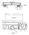
- each conveyor of the pairs of conveyors is advantageously provided with a rear lock mechanism 30 having a spring-loaded arm 32 which is normally in the "up" position and engages the end of carrier 10, to prevent any unintended displacement thereof.
- Arm 32 of mechanism 30 is pivotally mounted on its associated conveyor, and is urged upwardly by spring 33.
- arm 32 When in the "up" position and engaged, arm 32 lifts the adjacent end of carrier 10 off of rollers 6, as shown in solid line in Fig. 3, so that carrier 10 is supported only by arm 32, and the first roller of the conveyor. Rollers 6 may then freely rotate as carrier 8 is rolled thereon, while carrier 10 remains stationary.
- detent 12 forces arm 32 to pivot into the "down” position, thereby disengaging it from carrier 10, as shown in phantom in FIG. 3, so that carrier 10 may thereafter be moved.
- pallet 2 As pallet 2 pushes pallet 1 slightly uphill into position B, pallet 2 is simultaneously entering storage position A. As load positions A, B and C have the same dimensions and are equal in length to the pallets (the pallets all being of equal length), pallet 1 becomes entirely displaced into storage position B just as pallet 2 becomes positioned into storage position A.
- the fork lift truck may then lower pallet 2 onto carriers 10 which are extending through load positions A and B, with the sections of carrier 10 extending into storage position A having been uncovered by carriers 8 which are now supporting pallet 2 in storage position B.
- pallet 3 is delivered to the access side L and as was done previously with pallet 2, using the fork lift truck, pallet 3 is pushed against pallet 2, thereby simultaneously moving pallet 1 into storage position C, pallet 2 into storage position B, and pallet 3 into storage position A.
- Rear lock mechanism 30 having been previously released by the passage of carriers 8 thereover, allows carriers 10 to be displaced into load positions B and C during this final loading step.
- carriers 8 are within storage position C and carriers 10 are occupying load positions B and C, so that there are no carriers remaining in storage position A.
- pallet 3 when pallet 3 is deposited into storage position A by the fork lift truck, it rests directly on sections 5a and 5b of conveyors 4. As conveyor rollers 6 are partially enclosed by these sections, pallet 3 does not come into contact with rollers 6 which remain free to rotate. Sections 5a and 5b therefore support pallet 3 in the manner of an ordinary shelf, with pallet 3 not being rollable or slidable thereon.
- Pallet 3 is engaged by e.g., a fork lift truck, is lifted off of conveyor sections 5a and 5b and is backed out or removed from storage position A through access side L.
- Pallets 2 and 1 solely under the force of gravity roll on their carriers 10 and 8, respectively, downhill on conveyors 4 towards access side L, so that when pallet 3 is entirely withdrawn from the storage system, pallet 2 again occupies storage position A and pallet 1 rolls into storage position B.
- pallet 3 is withdrawn from storage position A in a smooth and gradual motion by the fork lift truck so that pallets 2 and 1 move towards access side L, at a rate of speed controlled by the receding fork lift truck.
- pallets 2 and 1 avoid an abrupt and jarring impact as pallet 2 and/or carrier 10 roll into stop 24 adjacent to access side L, which would otherwise occur if pallet 3 were quickly removed from the storage system.
- the rolling interaction occurs between rollers 6 and carriers 8 and 10
- the pallets themselves even though they may have uneven or broken bottom surfaces, may nevertheless be conveyed smoothly and reliably.
- pallet 2 With pallet 3 removed, pallet 2 once again occupies storage position A, with carrier 10 now in load positions A and B, and pallet 1 and carriers 8 disposed in storage position B. Pallet 2 can then be removed from storage system 1 by a fork lift truck through access side L, as was done previously during the removal of pallet 3. Finally, pallet 1 may also be removed from storage position A through access side L, as were the other pallets.
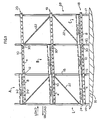
- FIG. 1 several layers of conveyors 4 may be provided in a stacked configuration on supports 14-17 creating levels 18-20 of storage lanes.
- Storage levels 19 and 20 have a construction and operation identical to that of level 18 previously described.
- the vertical spacings between levels 18-20 are determined generally according to the height of the loads carried by the pallets.
- Diagonal support bars 22 may be provided between supports 14-17 to provide a stronger structure.
- diagonal supports 22 disposed at the sides of the load positions do not at all interfere with the operation of the storage system. No access is required to rear surface 28 or to the sides of the storage system, thereby allowing it to be installed in a corner, against a wall, etc.
- conveyors 4 and carriers 8 and 10 have an exceptionally low profile thereby providing for a more effective use of space within the available volume of the storage system. Carriers 8 and 10, which are supported on the common rollers 6 of conveyors 4, also eliminate the need for separate support rollers for each carrier.
- the storage system may be multiplied or repeated in the lateral direction to provide additional storage space.
- the storage system could also be expanded vertically by extending supports 14-17 and by providing additional storage levels beyond the three levels 18-20 shown in Fig. 1.
- additional storage positions could be created by increasing the depth of the system, and by providing additional carriers and lock mechanisms.
- this storage system is ideally suited for a total of 3-7 storage positions.
Landscapes
- Engineering & Computer Science (AREA)
- Mechanical Engineering (AREA)
- Warehouses Or Storage Devices (AREA)
- Ultra Sonic Daignosis Equipment (AREA)
- Memory System Of A Hierarchy Structure (AREA)
- Pinball Game Machines (AREA)
Abstract
Description
- The invention relates to a gravity flow storage system for storing pallets comprising at least one pair of parallel and laterally spaced-apart conveyors (4) being disposed at an inclined angle to define a storage lane having a front lower end and a rear upper end; and at least one pair of pallet carrier sets, each of said sets disposed respectively on an associated conveyor (4), said sets comprising at least two nested telescoping pallet carriers (8, 10) including an innermost and an outermost pallet carrier, with said nested pallet carriers (8, 10) normally resting upon said conveyors (4) and being longitudinally displaceable on said associated conveyor (4), wherein corresponding pallet carriers (8, 10) of said carrier sets cooperate to support a pallet thereon such that said system is loadable by successively placing pallets onto corresponding carrieres at said front lower end (L) and moving the pallets on said corresponding carriers (8, 10) rolling on said conveyors (4) towards said rear upper end (28), beginning with said outermost carriers (8), and said system being conversely unloadable by successively removing pallets at said front lower end (L), thereby allowing any previously loaded pallets to move under the force of gravity towards said front lower end (L).
- In conventional drive-in or aisle-type fixed rack storage systems, lift trucks are required for every product or pallet movement. In contrast, a gravity flow or live storage system makes use of conveyors fitted with wheels or rollers, and suitable speed control devices, which are selected according to the type of pallet used in the system. The conveyors are inclined at a slight angle with respect to the floor. After a pallet is initially loaded into the system, it moves at a controlled speed under the force of gravity towards the lower end or discharge face of the rack system where it can be removed by fork lift, stacker, or other material handling equipment. This type of gravity flow storage system is frequently referred to as a "first in/first out" ("FIFO") storage system.
- These gravity flow systems can provide high storage density due to the elimination of access aisles previously needed to allow lift trucks to maneuver while loading and unloading pallets. In addition, the storage system operating requirements for fork lift truck operations, loading times, and operating personnel can be substantially reduced. Moreover, with such gravity flow storage systems, high storage density is also achieved because no empty space is left between the stored pallets, which abut each other under the force of gravity. In such storage systems, it is only necessary to access the loading face where the pallets are placed into the storage system, and the discharge face from where the pallets are removed. In between the loading and discharge faces, pallets move "downstream" automatically by gravity, without the assistance of any other operator-controlled material handling equipment.
- Such "FIFO" gravity flow storage systems have been quite successful for relatively large storage facilities. However, they typically are not suitable in small storage facilities where because of dimensional and configurational restrictions it is not possible to provide adequate access space for the loading and discharge ends of the rack system. For example, the storage area may be long and narrow with access available at only one narrow end. Moreover, even if sufficient access were available at both narrow ends of such a storage space, it might be more advantageous for applications where a variety of different products are being stored to have access to a large number of pallet storage lanes having a relatively short multi-pallet depth (e.g., 3-5 pallets) rather than just two or three long lanes.
- To accommodate such smaller storage facilities, a variety of "LIFO" (Last-in/First-out) gravity flow storage systems have been proposed wherein, the rollers or conveyors are inclined from the rear end of the rack, which is normally situated against a wall. The front end of the conveyor provides access for both loading and unloading pallets onto the rack. However, these storage systems have been relatively complex and often themselves occupy a substantial amount of space, thereby significantly reducing the available storage space in any particular application.
- Specifically, one known system known by GB-A 2 024 179 utilizes overlying or stacked carts having wheels which roll upon inclined rails. However, the overlying nature of the carts causes them to occupy additional height and width within the storage system, thereby wasting storage space. In addition, be- . cause they must carry the entire pallet weight directly, the overlying carts must be constructed from relatively large und heavy structural members, and include a centrally located support or cross beam. This not only takes up additional storage space, but it also requires the system structure be sufficient to carry not only the payload weight of the pallets, but also the substantial weight of the carts themselves. Moreover, the crossbeams of the carts tend to interfere with the insertion of lifting forks during fork-lift operations. In addition, each cart requires its own set of wheels.
- Another important consideration in rack storage is that the bottom surface of a conventional wooden pallet is generally poorly suited for acting as a roller facing or bearing surface. While it is possible that such pallets can be moved directly on wheel or roller conveyors in a flow storage system, their operation therein is erratic and pallets frequently "hang- up" in the upstream position. In such cases, operating personnel may be required to climb into the supporting structure to free "stuck" pallets, thereby subjecting themselves to possible injury. Similarly, broken or defective wooden pallets cannot be conveyed safely and reliably in conventional flow storage racks. Moreover, existing storage systems cannot easily handle "slave" pallets which are generally made of plywood or steel, and are usually from %" to 1―s" (19 to 38 mm) thick but without provision for lift truck forks to enter into the pallet itself. Hence the forks support the pallet on its bottom surface, and in such cases, existing systems using carts are not practical, because setting the pallet down on the cart is impossible, due to the position of the forks in between the cart and pallet.
- It is an object of the invention to provide a flow storage system which is of simple and economical construction, easy to use and install, and which is safe and reliable in operation, such a system being mainly defined by
claim 1. - Certain of the foregoing and related objects are readily attained in a gravity flow storage system for storing pallets comprising at least one pair of parallel and laterally spaced-apart conveyors having a plurality of parallel longitudinally spaced-apart rollers rotatably mounted in a frame. The conveyors are disposed at an inclined angle to define a storage lane having a front lower end and a rear upper end. At least one pair of pallet carrier sets are provided with each of the sets disposed respectively on an associated conveyor. The sets have at least two nested telescoping pallet carriers including an innermost and an outermost pallet carrier. The nested pallet carriers are normally resting upon the conveyor rollers and are longitudinally displaceable on their associated conveyor via the rollers thereof. Corresponding pallet carriers of the carrier sets cooperate to support a pallet thereon such that the system is loadable by successively placing pallets onto corresponding carriers at the front lower end and moving the pallets (e.g. by pushing the pallets with the next pallet to be loaded carried by a fork lift truck), on the corresponding carriers rolling on the rollers towards the rear upper end, beginning with the outermost carriers. The last pallet loaded into the storage system is placed directly on the conveyor frame or housing. The system is conversely unloadable by successively removing pallets at the front lower end, thereby allowing the previously loaded pallets to move under the force of gravity towards the front lower end.
- Preferably, the conveyors each include a pair of opposing generally C-shaped channel sections forming the conveyor frame and supporting the rollers therebetween. The carriers may be elongated, generally inverted U-shaped sections, disposed substantially in between the channel sections with the legs of the U-shaped sections resting on the rollers. The pallet carriers of each set which occupy the same relative positions within the sets have approximately the same lengths, and the pallet carriers within each set have lengths approximately equal to integer multiples of the length of the pallets.
- The lock means for preventing unintentional movement of the carriers toward the rear end includes a pair of spring-actuated levers, each of which is pivotally mounted on one of the conveyors for movement between an upper and lower position. The levers in the upper position are disposed to engage a carrier end such that the carrier end is lifted substantially off of the rollers of its associated conveyor. The levers in the lower position are then disengageable therefrom to allow intended passage of a carrier thereover. The storage system may additionally include a frame supporting the pair of conveyors. A multiplicity of vertically spaced-apart pairs of conveyors, supported by the frame to form a vertical column of storage lanes, may also be provided. Preferably the conveyors are at an inclination of about one-half inch per foot (4.17 percent).
- Other objects and features of the present invention will become apparent from the following detailed description when taken in connection with the accompanying drawings which disclose a single embodiment of the invention. It is to be understood that the drawings are designed for the purpose of illustration only, and are not intended as a definition of the limits of the invention.
- In the drawings, wherein similar reference characters denote similar elements throughout the several views:
- FIG. 1 is a schematical side elevational view of the storage system embodying the present invention;
- FIG. 2 is a fragmentarily-illustrated sectional view taken along line 2-2 of FIG. 1; and
- FIG. 3 is a fragmentarily-illustrated side elevational view on an enlarged scale of the rear lock mechanism illustrated in FIG 1, with the "up" position of the lock mechanism as it engages and lifts the innermost carrier shown in solid line, and the "down" position of lock mechanism as it is disengaged by an overlying carrier, in phantom line.
- Turning now in detail to the appended drawings, therein illustrated is a novel gravity flow storage system embodying the present invention which, as shown best in FIGS. 1 and 2, basically includes a multiplicity of paired spaced-apart,
parallel conveyors 4 mounted upon upstanding supports 14-17 at an inclined angle with respect to the floor orhorizontal H. Conveyors 4 are comprised of a frame composed of two opposing, generally C-shaped channel sections 5a, 5b holding a multiplicity of rotatably mounted and longitudinally spaced-apartparallel rollers 6. Eachconveyor 4 has a set of U-shaped pallet carriers arranged in a nested, telescoping manner normally resting atoprollers 6 betweenchannel sections 5a, 5b. The embodiment of the invention illustrated in FIG. 1 has three pallet-storage positions A, B and C. and correspondingly includes only afirst carrier 8 and asecond carrier 10 dimensioned so that it may be positioned completely within the envelope offirst carrier 8 in a telescoping-like manner. However, additional pallet storage positions, and in turn pallet conveyors, may be added according to the particular application. -
First carrier 8 is approximately equal to the length of the pallets to be loaded and stored in the system.Second carrier 10 is about twice as long asfirst carrier 8, and therefore extends onconveyor 4. through two storage positions. Bothcarriers conveyors 4 with a minimum amount of exerted force. - When no pallets are being stored within the system,
carriers conveyors 4 towards the lower or access and loading side L of the system. In operation, the first pallet to be loaded (pallet 1) is delivered through the access end L into storage position A by a fork lift truck or other material handling equipment.Pallet 1 is then lowered ontofirst carriers 8 and, e.g., the fork lift truck is withdrawn. To loadpallet 2, a fork lift truck deliverspallet 2 to access side L and then pushespallet 2 againstpallet 1 so thatpallet 1 and the first set ofcarriers 8 on whichpallet 1 is resting is displaced away from end L and slightly upwardly onconveyors 4 untilpallet 1 andcarriers 8 are entirely within storage position B. Aspallet 1 is pushed onconveyors 4 by the forklift pushing pallet 2,carriers 8 roll onrollers 6 ofconveyors 4 thereby causing therollers 6 over whichcarrier 8 is passing to rotate. Assecond carriers 10 are also resting on the rollers ofconveyors 4, there is a tendency for this movement offirst carriers 8 to causesecond carriers 10 to also be displaced from their original position, by virtue of the friction between the rotating rollers and the bottom surface ofsecond carriers 10. In order to prevent this from happening and to maintaincarrier 10 in its original position before it has received a pallet, each conveyor of the pairs of conveyors is advantageously provided with arear lock mechanism 30 having a spring-loadedarm 32 which is normally in the "up" position and engages the end ofcarrier 10, to prevent any unintended displacement thereof.Arm 32 ofmechanism 30 is pivotally mounted on its associated conveyor, and is urged upwardly byspring 33. When in the "up" position and engaged,arm 32 lifts the adjacent end ofcarrier 10 off ofrollers 6, as shown in solid line in Fig. 3, so thatcarrier 10 is supported only byarm 32, and the first roller of the conveyor.Rollers 6 may then freely rotate ascarrier 8 is rolled thereon, whilecarrier 10 remains stationary. Ascarrier 8 passes overlock mechanism 30,detent 12forces arm 32 to pivot into the "down" position, thereby disengaging it fromcarrier 10, as shown in phantom in FIG. 3, so thatcarrier 10 may thereafter be moved. - As
pallet 2 pushespallet 1 slightly uphill into position B,pallet 2 is simultaneously entering storage position A. As load positions A, B and C have the same dimensions and are equal in length to the pallets (the pallets all being of equal length),pallet 1 becomes entirely displaced into storage position B just aspallet 2 becomes positioned into storage position A. The fork lift truck may thenlower pallet 2 ontocarriers 10 which are extending through load positions A and B, with the sections ofcarrier 10 extending into storage position A having been uncovered bycarriers 8 which are now supportingpallet 2 in storage position B. - The last pallet to be loaded in this embodiment,
pallet 3, is delivered to the access side L and as was done previously withpallet 2, using the fork lift truck,pallet 3 is pushed againstpallet 2, thereby simultaneously movingpallet 1 into storage position C,pallet 2 into storage position B, andpallet 3 into storage position A.Rear lock mechanism 30 having been previously released by the passage ofcarriers 8 thereover, allowscarriers 10 to be displaced into load positions B and C during this final loading step. At this point,carriers 8 are within storage position C andcarriers 10 are occupying load positions B and C, so that there are no carriers remaining in storage position A. Thus, whenpallet 3 is deposited into storage position A by the fork lift truck, it rests directly onsections 5a and 5b ofconveyors 4. Asconveyor rollers 6 are partially enclosed by these sections,pallet 3 does not come into contact withrollers 6 which remain free to rotate.Sections 5a and 5b thereforesupport pallet 3 in the manner of an ordinary shelf, withpallet 3 not being rollable or slidable thereon. - In order to remove or unload pallets from the storage system, the loading sequence of steps is followed in reverse order.
Pallet 3 is engaged by e.g., a fork lift truck, is lifted off ofconveyor sections 5a and 5b and is backed out or removed from storage position A through access side L. Aspallet 3 is withdrawn,pallets carriers conveyors 4 towards access side L, so that whenpallet 3 is entirely withdrawn from the storage system,pallet 2 again occupies storage position A andpallet 1 rolls into storage position B. As this occurs,carriers 8 slide off ofrear lock mechanism 30 which then pivots back into its locked "up" position under the influence ofspring 33, asarm 32 is no longer depressed or held down into the unlocked "down" position bycarrier 10. Preferably,pallet 3 is withdrawn from storage position A in a smooth and gradual motion by the fork lift truck so thatpallets pallets pallet 2 and/orcarrier 10 roll intostop 24 adjacent to access side L, which would otherwise occur ifpallet 3 were quickly removed from the storage system. As the rolling interaction occurs betweenrollers 6 andcarriers - With
pallet 3 removed,pallet 2 once again occupies storage position A, withcarrier 10 now in load positions A and B, andpallet 1 andcarriers 8 disposed in storageposition B. Pallet 2 can then be removed fromstorage system 1 by a fork lift truck through access side L, as was done previously during the removal ofpallet 3. Finally,pallet 1 may also be removed from storage position A through access side L, as were the other pallets. - As shown in FIG. 1, several layers of
conveyors 4 may be provided in a stacked configuration on supports 14-17 creating levels 18-20 of storage lanes.Storage levels level 18 previously described. The vertical spacings between levels 18-20 are determined generally according to the height of the loads carried by the pallets. Diagonal support bars 22 may be provided between supports 14-17 to provide a stronger structure. As pallets are loaded and unloaded only through access side L,diagonal supports 22 disposed at the sides of the load positions do not at all interfere with the operation of the storage system. No access is required to rearsurface 28 or to the sides of the storage system, thereby allowing it to be installed in a corner, against a wall, etc. In addition, due to the fact that the paired conveyors are laterally spaced apart without any lateral interconnection, the forks of a fork lift truck may be quickly and easily engaged underneath wooden or slave pallets, without the need for precise alignment. As best illustrated in FIG. 2,conveyors 4 andcarriers Carriers common rollers 6 ofconveyors 4, also eliminate the need for separate support rollers for each carrier. - Of course, the storage system may be multiplied or repeated in the lateral direction to provide additional storage space. Moreover, the storage system could also be expanded vertically by extending supports 14-17 and by providing additional storage levels beyond the three levels 18-20 shown in Fig. 1. In addition, although the embodiment illustrated includes three storage positions, i.e., A, B and C, additional storage positions could be created by increasing the depth of the system, and by providing additional carriers and lock mechanisms. However, this storage system is ideally suited for a total of 3-7 storage positions. It should also be apparent that other variations might also be possible, and would be apparent to those skilled in the art. For example, it may be possible to have interlocking carriers all of about the same length, and linked to each other in a telescope-like structure. It may also be possible to provide a place of the lock mechanism, a plurality of rows of split rollers, with each row aligned with a leg of a downwardly facing U-shaped carrier.
Claims (5)
Priority Applications (1)
| Application Number | Priority Date | Filing Date | Title |
|---|---|---|---|
| AT86111918T ATE53982T1 (en) | 1986-04-10 | 1986-08-28 | LIQUID STORAGE SYSTEM USING GRAVITY. |
Applications Claiming Priority (2)
| Application Number | Priority Date | Filing Date | Title |
|---|---|---|---|
| US850227 | 1986-04-10 | ||
| US06/850,227 US4715765A (en) | 1986-04-10 | 1986-04-10 | Gravity flow storage system |
Publications (2)
| Publication Number | Publication Date |
|---|---|
| EP0241579A1 EP0241579A1 (en) | 1987-10-21 |
| EP0241579B1 true EP0241579B1 (en) | 1990-06-20 |
Family
ID=25307602
Family Applications (1)
| Application Number | Title | Priority Date | Filing Date |
|---|---|---|---|
| EP86111918A Expired - Lifetime EP0241579B1 (en) | 1986-04-10 | 1986-08-28 | Gravity flow storage system |
Country Status (6)
| Country | Link |
|---|---|
| US (1) | US4715765A (en) |
| EP (1) | EP0241579B1 (en) |
| JP (1) | JPS62255302A (en) |
| AT (1) | ATE53982T1 (en) |
| CA (1) | CA1270789A (en) |
| DE (1) | DE3672124D1 (en) |
Families Citing this family (29)
| Publication number | Priority date | Publication date | Assignee | Title |
|---|---|---|---|---|
| WO1988005398A1 (en) * | 1987-01-26 | 1988-07-28 | Babcock Energy Limited | Apparatus for stowing and deploying stores from air and marine craft |
| US4936738A (en) * | 1988-04-26 | 1990-06-26 | Food Plant Engineering, Inc. | Alternating push back selective rack storage system |
| FI79818C (en) * | 1988-06-01 | 1990-03-12 | Kone Oy | Procedure and plant for storage and displacement of pallets or equivalent |
| DE3920405C1 (en) * | 1989-06-22 | 1990-03-29 | Goldschmidt, Sol, Zuerich, Ch | |
| US4982851A (en) * | 1990-02-07 | 1991-01-08 | Konstant Anthony N | Supported pallet rack |
| US5180069A (en) * | 1990-12-06 | 1993-01-19 | Advance Storage Products | Four-deep push-back warehouse storage rack system |
| US5224828A (en) * | 1991-09-17 | 1993-07-06 | Creative Storage Systems, Inc. | Pallet brake track assembly |
| US5350270A (en) * | 1991-10-09 | 1994-09-27 | Qube, Inc. | Pickface conveyor |
| US5178288A (en) * | 1991-11-18 | 1993-01-12 | Interroll Canada Limited | Push back pallet rack |
| US5285909A (en) * | 1993-02-04 | 1994-02-15 | Slater Robert C | Pallet storage rack |
| US5415300A (en) * | 1993-11-05 | 1995-05-16 | Krummell; John V. R. | Push-back cart storage system |
| US5524776A (en) * | 1993-12-17 | 1996-06-11 | Hall; Roger W. | Low inclination push back storage rack system |
| US5638965A (en) * | 1994-12-23 | 1997-06-17 | The Interlake Companies, Inc. | Cartless push-back rack |
| DE29711710U1 (en) * | 1997-07-04 | 1997-09-11 | Nedcon Magazijninrichting Bv | Flow rack for order picking |
| US6267258B1 (en) | 1999-05-07 | 2001-07-31 | Gilmour, Inc. | Gravity feed pull out shelf with rear storage area and associated method for displaying and storing a product |
| US6230908B1 (en) * | 1999-09-01 | 2001-05-15 | Dell Usa, L.P. | Flow rack with reverse flow limiting device |
| CA2336502A1 (en) * | 2000-07-12 | 2002-01-12 | Ridg-U-Rak, Inc. | Push back storage rack system |
| ES2226548B2 (en) * | 2002-12-05 | 2006-09-01 | Mecalux, S.A. | PERFECTED STRUCTURE FOR "PUSH BACK" PALLET STORAGE SYSTEMS. |
| US20040112260A1 (en) * | 2002-12-10 | 2004-06-17 | Allan Grainger | Support apparatus |
| EP1757540B1 (en) * | 2004-05-13 | 2011-01-05 | Mecalux, S.A. | Improved structure for push-back pallet storage systems |
| US7214024B2 (en) * | 2005-02-02 | 2007-05-08 | Mecalux, S.A. | Push back pallet storage system |
| CA2547592A1 (en) | 2005-05-23 | 2006-11-23 | Thomas Scott Richter | Flow through article storage device |
| US7770903B2 (en) * | 2007-02-26 | 2010-08-10 | Konstant Products, Inc. | Drawer type storage cart |
| US9630545B1 (en) | 2011-01-06 | 2017-04-25 | Jkc Development, Inc. | Apparatus and system for facilitating loading and unloading cargo from cargo spaces of vehicles |
| US9056577B2 (en) | 2011-01-06 | 2015-06-16 | Jkc Development, Inc. | Apparatus and system for facilitating loading and unloading cargo from cargo spaces of vehicles |
| US10106293B2 (en) | 2014-11-03 | 2018-10-23 | Fred E. Clark | Pallet for the storage and transportation of articles |
| US9522816B2 (en) * | 2015-05-05 | 2016-12-20 | Kenneth Taylor | Apparatus and method for moving catalyst bins |
| US10934093B2 (en) * | 2017-11-14 | 2021-03-02 | United Parcel Service Of America, Inc | Automated package transport vehicle |
| SE543416C2 (en) | 2018-11-27 | 2021-01-12 | Eab Ab | A method, a computer program and a device for transporting pallets |
Family Cites Families (8)
| Publication number | Priority date | Publication date | Assignee | Title |
|---|---|---|---|---|
| US3837511A (en) * | 1971-10-22 | 1974-09-24 | N Howlett | Method of loading and unloading articles in a storage apparatus |
| US4197047A (en) * | 1975-11-28 | 1980-04-08 | Weelpal Ag | Shelf storage system |
| US4168780A (en) * | 1978-03-16 | 1979-09-25 | Engineered Products | Flow rail rack |
| DE2829325C3 (en) * | 1978-07-04 | 1981-10-22 | Döring, Erich, 9442 Berneck, Sankt Gallen | High rack for panels |
| US4304521A (en) * | 1978-12-08 | 1981-12-08 | Hammond Theodore A | Method for handling palletized loads |
| US4462500A (en) * | 1982-05-19 | 1984-07-31 | Speedrack, Inc. | Multiple location storage bays |
| US4527937A (en) * | 1983-05-13 | 1985-07-09 | Orion Automation Industries | Automatic storage and distribution system |
| US4613270A (en) * | 1983-11-17 | 1986-09-23 | Speedrack, Inc. | Storage rack having bays with multiple rails and interlocking trolleys |
-
1986
- 1986-04-10 US US06/850,227 patent/US4715765A/en not_active Expired - Fee Related
- 1986-07-02 CA CA000512910A patent/CA1270789A/en not_active Expired - Lifetime
- 1986-08-28 AT AT86111918T patent/ATE53982T1/en not_active IP Right Cessation
- 1986-08-28 EP EP86111918A patent/EP0241579B1/en not_active Expired - Lifetime
- 1986-08-28 DE DE8686111918T patent/DE3672124D1/en not_active Expired - Lifetime
-
1987
- 1987-04-09 JP JP62088599A patent/JPS62255302A/en active Pending
Also Published As
| Publication number | Publication date |
|---|---|
| CA1270789C (en) | 1990-06-26 |
| DE3672124D1 (en) | 1990-07-26 |
| JPS62255302A (en) | 1987-11-07 |
| US4715765A (en) | 1987-12-29 |
| EP0241579A1 (en) | 1987-10-21 |
| ATE53982T1 (en) | 1990-07-15 |
| CA1270789A (en) | 1990-06-26 |
Similar Documents
| Publication | Publication Date | Title |
|---|---|---|
| EP0241579B1 (en) | Gravity flow storage system | |
| US4462500A (en) | Multiple location storage bays | |
| US4773546A (en) | Pallet rack | |
| US4982851A (en) | Supported pallet rack | |
| CA1327166C (en) | Multiple pallet rack | |
| US4341313A (en) | Shelving for pallets | |
| US4988251A (en) | Multiple load storage rack structure | |
| US5141118A (en) | Multiple carriage based rack assembly | |
| US5419444A (en) | Low profile push-back rack assembly | |
| US4197047A (en) | Shelf storage system | |
| CA2098433C (en) | Pallet storage system | |
| US5476180A (en) | Cart return device | |
| IE46129B1 (en) | Storage racks for warehouses and the like | |
| EP0164387B1 (en) | A storage and handling installation for palletised goods | |
| MXPA04010361A (en) | Pushback cart storage system. | |
| US7114904B2 (en) | Push-back pallet storage system | |
| US3524412A (en) | Inclined ramp which enables a wheeled base to traverse therealong in a horizontal position | |
| US4199290A (en) | Material handling apparatus | |
| WO2005095235A1 (en) | Compact pushback storing system for pallets | |
| JPH0798582B2 (en) | Loading method | |
| JP3369758B2 (en) | Automatic warehouse | |
| JPH0610210U (en) | Slide-type article storage mechanism for article storage shelves | |
| CA2151315C (en) | Cart return system | |
| JP2001010705A (en) | Storing device | |
| JP3020342U (en) | Goods storage shelves |
Legal Events
| Date | Code | Title | Description |
|---|---|---|---|
| PUAI | Public reference made under article 153(3) epc to a published international application that has entered the european phase |
Free format text: ORIGINAL CODE: 0009012 |
|
| AK | Designated contracting states |
Kind code of ref document: A1 Designated state(s): AT BE CH DE FR GB IT LI LU NL SE |
|
| 17P | Request for examination filed |
Effective date: 19880317 |
|
| 17Q | First examination report despatched |
Effective date: 19890323 |
|
| RAP3 | Party data changed (applicant data changed or rights of an application transferred) |
Owner name: AGNOFF, CHARLES |
|
| GRAA | (expected) grant |
Free format text: ORIGINAL CODE: 0009210 |
|
| AK | Designated contracting states |
Kind code of ref document: B1 Designated state(s): AT BE CH DE FR GB IT LI LU NL SE |
|
| PG25 | Lapsed in a contracting state [announced via postgrant information from national office to epo] |
Ref country code: SE Effective date: 19900620 Ref country code: AT Effective date: 19900620 |
|
| REF | Corresponds to: |
Ref document number: 53982 Country of ref document: AT Date of ref document: 19900715 Kind code of ref document: T |
|
| ITF | It: translation for a ep patent filed |
Owner name: SOCIETA' ITALIANA BREVETTI S.P.A. |
|
| DIN2 | Information on inventor provided after grant (deleted) | ||
| REF | Corresponds to: |
Ref document number: 3672124 Country of ref document: DE Date of ref document: 19900726 |
|
| RAP2 | Party data changed (patent owner data changed or rights of a patent transferred) |
Owner name: INTERROLL HOLDING AG |
|
| RIN2 | Information on inventor provided after grant (corrected) |
Free format text: AGNOFF, CHARLES |
|
| ET | Fr: translation filed | ||
| PG25 | Lapsed in a contracting state [announced via postgrant information from national office to epo] |
Ref country code: LU Free format text: LAPSE BECAUSE OF NON-PAYMENT OF DUE FEES Effective date: 19900831 |
|
| PLBE | No opposition filed within time limit |
Free format text: ORIGINAL CODE: 0009261 |
|
| STAA | Information on the status of an ep patent application or granted ep patent |
Free format text: STATUS: NO OPPOSITION FILED WITHIN TIME LIMIT |
|
| 26N | No opposition filed | ||
| ITTA | It: last paid annual fee | ||
| PGFP | Annual fee paid to national office [announced via postgrant information from national office to epo] |
Ref country code: FR Payment date: 19920623 Year of fee payment: 7 |
|
| PGFP | Annual fee paid to national office [announced via postgrant information from national office to epo] |
Ref country code: BE Payment date: 19920625 Year of fee payment: 7 |
|
| PGFP | Annual fee paid to national office [announced via postgrant information from national office to epo] |
Ref country code: GB Payment date: 19920629 Year of fee payment: 7 |
|
| PGFP | Annual fee paid to national office [announced via postgrant information from national office to epo] |
Ref country code: CH Payment date: 19920821 Year of fee payment: 7 |
|
| PGFP | Annual fee paid to national office [announced via postgrant information from national office to epo] |
Ref country code: NL Payment date: 19920831 Year of fee payment: 7 |
|
| PGFP | Annual fee paid to national office [announced via postgrant information from national office to epo] |
Ref country code: DE Payment date: 19921030 Year of fee payment: 7 |
|
| PG25 | Lapsed in a contracting state [announced via postgrant information from national office to epo] |
Ref country code: GB Effective date: 19930828 |
|
| PG25 | Lapsed in a contracting state [announced via postgrant information from national office to epo] |
Ref country code: LI Effective date: 19930831 Ref country code: CH Effective date: 19930831 Ref country code: BE Effective date: 19930831 |
|
| BERE | Be: lapsed |
Owner name: INTERROLL HOLDING A.G. Effective date: 19930831 |
|
| PG25 | Lapsed in a contracting state [announced via postgrant information from national office to epo] |
Ref country code: NL Effective date: 19940301 |
|
| NLV4 | Nl: lapsed or anulled due to non-payment of the annual fee | ||
| GBPC | Gb: european patent ceased through non-payment of renewal fee |
Effective date: 19930828 |
|
| PG25 | Lapsed in a contracting state [announced via postgrant information from national office to epo] |
Ref country code: FR Effective date: 19940429 |
|
| REG | Reference to a national code |
Ref country code: CH Ref legal event code: PL |
|
| PG25 | Lapsed in a contracting state [announced via postgrant information from national office to epo] |
Ref country code: DE Effective date: 19940503 |
|
| REG | Reference to a national code |
Ref country code: FR Ref legal event code: ST |
|
| PG25 | Lapsed in a contracting state [announced via postgrant information from national office to epo] |
Ref country code: IT Free format text: LAPSE BECAUSE OF NON-PAYMENT OF DUE FEES;WARNING: LAPSES OF ITALIAN PATENTS WITH EFFECTIVE DATE BEFORE 2007 MAY HAVE OCCURRED AT ANY TIME BEFORE 2007. THE CORRECT EFFECTIVE DATE MAY BE DIFFERENT FROM THE ONE RECORDED. Effective date: 20050828 |