EP0241499B1 - Ventil für konstante luftdurchflussmenge - Google Patents
Ventil für konstante luftdurchflussmenge Download PDFInfo
- Publication number
- EP0241499B1 EP0241499B1 EP86905821A EP86905821A EP0241499B1 EP 0241499 B1 EP0241499 B1 EP 0241499B1 EP 86905821 A EP86905821 A EP 86905821A EP 86905821 A EP86905821 A EP 86905821A EP 0241499 B1 EP0241499 B1 EP 0241499B1
- Authority
- EP
- European Patent Office
- Prior art keywords
- flow rate
- throttling
- passage section
- gas flow
- valve according
- Prior art date
- Legal status (The legal status is an assumption and is not a legal conclusion. Google has not performed a legal analysis and makes no representation as to the accuracy of the status listed.)
- Expired - Lifetime
Links
Images

Classifications
-
- F—MECHANICAL ENGINEERING; LIGHTING; HEATING; WEAPONS; BLASTING
- F24—HEATING; RANGES; VENTILATING
- F24F—AIR-CONDITIONING; AIR-HUMIDIFICATION; VENTILATION; USE OF AIR CURRENTS FOR SCREENING
- F24F11/00—Control or safety arrangements
- F24F11/70—Control systems characterised by their outputs; Constructional details thereof
- F24F11/72—Control systems characterised by their outputs; Constructional details thereof for controlling the supply of treated air, e.g. its pressure
- F24F11/74—Control systems characterised by their outputs; Constructional details thereof for controlling the supply of treated air, e.g. its pressure for controlling air flow rate or air velocity
- F24F11/75—Control systems characterised by their outputs; Constructional details thereof for controlling the supply of treated air, e.g. its pressure for controlling air flow rate or air velocity for maintaining constant air flow rate or air velocity
-
- Y—GENERAL TAGGING OF NEW TECHNOLOGICAL DEVELOPMENTS; GENERAL TAGGING OF CROSS-SECTIONAL TECHNOLOGIES SPANNING OVER SEVERAL SECTIONS OF THE IPC; TECHNICAL SUBJECTS COVERED BY FORMER USPC CROSS-REFERENCE ART COLLECTIONS [XRACs] AND DIGESTS
- Y10—TECHNICAL SUBJECTS COVERED BY FORMER USPC
- Y10T—TECHNICAL SUBJECTS COVERED BY FORMER US CLASSIFICATION
- Y10T137/00—Fluid handling
- Y10T137/7722—Line condition change responsive valves
- Y10T137/7781—With separate connected fluid reactor surface
- Y10T137/7784—Responsive to change in rate of fluid flow
- Y10T137/7787—Expansible chamber subject to differential pressures
- Y10T137/7791—Pressures across flow line valve
-
- Y—GENERAL TAGGING OF NEW TECHNOLOGICAL DEVELOPMENTS; GENERAL TAGGING OF CROSS-SECTIONAL TECHNOLOGIES SPANNING OVER SEVERAL SECTIONS OF THE IPC; TECHNICAL SUBJECTS COVERED BY FORMER USPC CROSS-REFERENCE ART COLLECTIONS [XRACs] AND DIGESTS
- Y10—TECHNICAL SUBJECTS COVERED BY FORMER USPC
- Y10T—TECHNICAL SUBJECTS COVERED BY FORMER US CLASSIFICATION
- Y10T137/00—Fluid handling
- Y10T137/7722—Line condition change responsive valves
- Y10T137/7781—With separate connected fluid reactor surface
- Y10T137/7784—Responsive to change in rate of fluid flow
- Y10T137/7792—Movable deflector or choke
Definitions
- the present invention relates to a constant gas flow rate valve having a throttling member located in a flow passage defined by a passage section, the throttling member, having a throttling part changing shape under the effect of changes in the pressure differential across the valve so that the free flow area between the walls of the passage section and the throttling part varies as the pressure differential varies, the projection of the throttling part on a plane perpendicular to the central axis of the passage section having a substantially circular circumscribing shape.
- a constant gas flow rate valve of this type has been disclosed in US 3718160.
- the valve has an elastic throttling member located in the gas flow passage, the throttling member having a substantially circular cross-section and a wavy shape, the wave peaks and troughs running circumferentially.
- the throttling member changes shape so that the free flow area is reduced.
- the higher the pressure differential the smaller the free flow area becomes; similarly decreasing the pressure differential causes the free flow area to increase. In this way the gas flow rate through the valve is kept approximately constant.
- This form of throttling member has the disadvantage that the "bellows" structure is susceptible to vibration and cannot control the flow accurately.
- EP 0027068 shows a similar valve, in which the shape changes of the throttling member are controlled by spring means. In both valves the changes in width of the free flow area are not uniform over the entire cross section of the valve.
- the valve should be inexpensive to manufacture.
- the invention provides a constant gas flow rate valve in which the throttling member can assume in one extreme position a wavy shape in which the wave peaks and troughs run substantially parallel to the central axis of the passage section.
- the passage section has a changing cross section that varies along the central axis of the passage section, a conical shape being particularly suitable.
- the throttling member preferably comprises a throttling part of elastic material.
- the constant gas flow rate valve of the invention can be constructed so that independently of the variations of free flow area with variation in the pressure differential, the space between the walls of the passage section and the throttling member can be altered in order to adjust the set gas flow rate. This may be achieved by moving the throttling member relative to the passage section; preferably it is moved parallel to the central axis of the passage section, shaft means being provided along with the throttling member may be displaced. Preferably the shaft means is located on the central axis of the passage section.
- Spring means may be provided associated with the throttling member and biasing the throttling member into a given shape.
- the throttling member comprises a body part, the throttling part and a curved flow deflector on an upstream surface, the spring means being located around the body part in an equalising space defined between the body part and the throttling part.
- the periphery of the throttling member increases when the pressure differential increases and decreases when the pressure differential decreases, the entire circumference of the throttling part moving towards the passage section.
- the substantially circular configuration of the throttling member allows throttling and adjustment of the flow rate to be generally uniform around the periphery of the throttling member.
- the valve according to the invention may thus allow substantially stepless adjustment of the set gas flow rate within a wide range of flow rates; the valve can be arranged so that at one extreme position, it is fully closed.
- the valve may also be simple to construct and have advantages in manufacture.
- Fig. 1 is depicted a constant air flow rate valve according to the invention, in elevational sectioned view, the spring of the constant airflow rate valve having been schematically indicated in this figure.
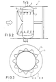
- Fig. 2 are illustrated the two extreme positions of the constant air flow rate valve of the invention, these positions being indicated with symbols C 1 and C 2 , respectively.
- Fig. 3 In Fig. 3 are shown said extreme positions C 1 and C 2 of Fig. 2 along the section lines A-A and B-B, whereof the section plane A-A represents one extreme position C 1 and section plane B-B represents the other extreme position C 2 .
- the constant air flow rate valve 1 comprises a throttling member, which has been indicated with the general reference numeral 2.
- the throttling member 2 comprises a throttling part 3 made of an elastic material, preferably of silicone.
- the throttling part 3 has a flow-throttling portion 3a, and at its ends a first end portion 3b and at the other end a second end portion 3c.
- the first end portion 3b carries a spring fixing shoulder or another equivalent spring fixing part 3b i , and on the same end is also located the first fixing border 3b 2 for the throttling part 3.
- In the other end portion 3c is located the second fixing border 3 C1 for the throttling part 3.
- the throttling member 2 comprises a body part 4, consisting of a main body 4a and a fixing disk 4b attaching thereto substantially in its central area.
- the fixing disk 4b carries fixing means 4b 1 for the end of the spring, these being preferably formed by cavities in which one end of the spring can be placed and in which the spring is thus firmly held.
- the fixing disk 4b also comprises a second fixing border 3b 2 for the throttling part 3, fixing means 4b 2 , likewise preferably formed by a cavity, the second border 3b 2 of the throttling part 3 being placeable and fixable in this cavity.
- the main body 4a is advantageously an elongated, cylindrical body part having on its central axis an elongated threaded hole 4a,, closed at one end, for the shaft 10.
- the threads provided on the shaft 10 and in the threaded hole 4a, in the body 4 are compatible as to their thread systems so that the body 4 can be rotated on the shaft 10 in the direction of the central axis X 1 .
- the body 4 has also been provided with a threaded hole 4a 2 for the set-point value locking screw 9. This enables the throttling member 2 to be locked in a given position on the shaft 10.
- an expansion chamber 6 in this chamber being accommodated a spring 5, preferably a compression spring.
- the chamber 6 communicates by an air aperture 7 with the entrance chamber 8 and, further, through the central aperture 11 a in the flow deflector part 11 with the air space on the incoming air flow side of the throttling member 2. Said air communication has expressly been provided to enable air to flow through the apertures 11 a and 7 into the expansion chamber 6 when the throttling part 3 changes shape.
- the shaft 10 has expressly been provided for set-point fixing.
- the throttling member 2 can be displaced in the direction of the central axis of the shaft 10 to assume the position on the shaft 10 which is desired in each particular instance, and, thereby, the desired position in relation to the passage structures of the valve.
- the air flow deflector part 11 has been attached to the throttling part 3 in the region between the throttling portion 3a and the first end portion 3b.
- the flow deflector part 11 is a part with curved surface and its effect is, by its curvature, to deflect the flow smoothly to pass along the flow path defined between the throttling part 3 and the passage.
- the flow deflector part 11 has a central air aperture 11a, through which air is enabled to flow into the chamber 8 and, further, through the air aperture 7 into the equalizing chamber 6, or vice versa, depending on whether the throttling of the air flow is being increased or reduced, i.e., whether the chamber 6 expands or contracts.
- the locking part 12 is located at one very end of the body 4a. It is possible by means of the locking part 12 to ensure the holding of the first fixing border 3b 2 of the throttling part in contiguity with the body proper, 4.
- the fixing part 12 is provided with a central flow aperture, and it has on one end a shoulder 12a which urges the fixing border of the throttling part 3 into the cavity in the main body 4a and holds it there.
- the shaft 10 is attached to a yoke part 13, which is further fixedly positioned in relation to the valve passage 14.
- the valve is provided with a set-point scale, this scale being advantageously marked on the shaft 10.
- the valve passage 14 is most advantageously a conical body.
- the passage section 14 has a flow surface 14a obliquely positioned in relation to the central axis X 1 .
- Its flow cross section is substantially circular, and consequently the central axis X 1 .
- the passage section 14 flares out conically.
- Its flow cross section is substantially circular, and consequently the central axis X 1 is, at the same time, the axis of symmetry for the passage section.
- the spring 5 is fitted with one end to the throttling part 3 and with its other end to the fixing disk 4b on the body 4 of the throttling member 2, in its spring end fixing means 4b i , which preferably consist of cavities. On the other end, the spring 5 is attached to the throttling part 3 itself, to its first end portion 3b. It is fixed on said first end portion 3b with the air of a spring fixing shoulder 3b, or equivalent.
- the valve is adjusted to pass an air flow of given magnitude, independent of the differential pressures, by setting the throttling member 2 in a given position on the central axis X 1 of the passage section 14. Since the passage section 14 expands in conical fashion, it is obvious that when the throttling member 2 is displaced in the direction of the central axis X 1 the throttling member 2 can always be made to be located at desired distance from the flow surface 14a disposed obliquely in relation to the central axis X 1 of the passage section 14.
- the throttling regions of the throttling part 3 of the throttling member 2 are located very close to the flow surface 14a of the passage section 14. In this case a set-point has been imposed at which the least possible air flow is admitted to pass through the valve.
- the throttling member 2 is located as far away as possible from the intake aperture A through which the air enters the valve, the throttling part 3 of throttling member 2 is located as far as possible from the flow surface 14a of the passage section 14, and the greatest possible flow is admitted through the valve.
- the shaft 10 is in this case fixedly carried in the yoke 13, this yoke 13 further being fixedly located in relation to the passage section 14. It is obvious that the control procedure may equally be implemented in such manner that the shaft 10 is fixedly attached to the throttling member 2, the throttling member 2 together with the shaft 10 then being rotated in threads provided in the yoke 13.
- C 1 indicates that shape of the throttling part 3 with which the flow aperture is at its largest.
- C 2 indicates in this figure that shape of the throttling part 3 with which the flow aperture is smallest.
- Fig. 3 illustrates these two extreme shapes of the throttling part 3, in cross section and shown as sectioned along the lines A-A and B-B in Fig. 2.
- the throttling portion wall ofthethrottling part3 is pleated in undulating fashion (section A-A). This wavy shape enables the throttling part 3 to expand towards the flow surface 14a of the passage section 14.
- C 2 in Fig. 3 indicates this throttling part 3 when fully expanded, in which case the cross section shape is circular (section B-B).
- the crests and dales of the waves occurring here run parallel to the central axis X 1 .
- the shaft 10 is a guide with rectangular cross section, on which the throttling member 2 can be secured in various positions with the aid of a locking screw or equivalent.
- the guide carries on one face a scale for different flow rate settings.
- the chamber 8 serves as a damping means preventing resonance vibrations of the throttling part 3.
- a wide chamber space has been established at the point 8' in the body part 4a of the throttling member 2, communication being provided therefrom to the space on the incoming flow side, and one or several air apertures to the equalizing space 6.
- the respective chamber in the body part 4a will then operate as a highly effective resonance damping means, and no anterior chamber 8 is then needed in this embodiment.
Landscapes
- Physics & Mathematics (AREA)
- Fluid Mechanics (AREA)
- Engineering & Computer Science (AREA)
- Chemical & Material Sciences (AREA)
- Combustion & Propulsion (AREA)
- Mechanical Engineering (AREA)
- General Engineering & Computer Science (AREA)
- Safety Valves (AREA)
- Lift Valve (AREA)
Claims (16)
Priority Applications (1)
| Application Number | Priority Date | Filing Date | Title |
|---|---|---|---|
| AT86905821T ATE60425T1 (de) | 1985-09-27 | 1986-09-25 | Ventil fuer konstante luftdurchflussmenge. |
Applications Claiming Priority (2)
| Application Number | Priority Date | Filing Date | Title |
|---|---|---|---|
| FI853751 | 1985-09-27 | ||
| FI853751A FI74798C (fi) | 1985-09-27 | 1985-09-27 | Ventil med standardluftmaengd och foerfarande foer reglering av en ventil med standardluftmaengd. |
Publications (2)
| Publication Number | Publication Date |
|---|---|
| EP0241499A1 EP0241499A1 (de) | 1987-10-21 |
| EP0241499B1 true EP0241499B1 (de) | 1991-01-23 |
Family
ID=8521422
Family Applications (1)
| Application Number | Title | Priority Date | Filing Date |
|---|---|---|---|
| EP86905821A Expired - Lifetime EP0241499B1 (de) | 1985-09-27 | 1986-09-25 | Ventil für konstante luftdurchflussmenge |
Country Status (5)
| Country | Link |
|---|---|
| US (1) | US4827971A (de) |
| EP (1) | EP0241499B1 (de) |
| DE (1) | DE3677203D1 (de) |
| FI (1) | FI74798C (de) |
| WO (1) | WO1987002120A1 (de) |
Family Cites Families (18)
| Publication number | Priority date | Publication date | Assignee | Title |
|---|---|---|---|---|
| US2740418A (en) * | 1951-08-06 | 1956-04-03 | Phillips Petroleum Co | Combined excess flow and shut off valve |
| US2925826A (en) * | 1955-01-17 | 1960-02-23 | Dole Valve Co | Variable flow controller |
| US3022977A (en) * | 1958-09-25 | 1962-02-27 | Sam A Jones | Vacuum operated normally closed valve |
| US3255963A (en) * | 1963-06-26 | 1966-06-14 | Boston Fluid Control Corp | Thermostatically determined constant volume fluid supply system |
| DE2019862C3 (de) * | 1970-04-24 | 1980-06-26 | Rox Lufttechnische Geraetebau Gmbh, 5000 Koeln | Regler zum Konstanthalten des Volumenstroms fur gasförmige Medien, insbesondere fur Hochdruckklimaanlagen |
| US3718160A (en) * | 1971-04-01 | 1973-02-27 | Serva Soc | Device for controlling air flow in ventilation pipes |
| BE790530A (fr) * | 1971-11-02 | 1973-02-15 | Svenska Flaektfabriken Ab | Dispositif de commande d'ecoulement, de preference pour de l'air et d'autres milieux gazeux |
| CH555519A (de) * | 1972-09-05 | 1974-10-31 | Sulzer Ag | Einrichtung zur individuellen klimatisierung der einzelnen raeume eines gebaeudes. |
| JPS5535615B2 (de) * | 1974-04-23 | 1980-09-16 | ||
| DE2617830C2 (de) * | 1976-04-23 | 1986-05-15 | Gebrüder Trox, GmbH, 4133 Neukirchen-Vluyn | Regelventil zur Aufrechterhaltung eines konstanten Volumenstroms, insbesondere in klimatechnischen Anlagen |
| DE2649307A1 (de) * | 1976-10-29 | 1978-05-03 | Trox Gmbh Geb | Luftkanalabschnitt fuer insbesondere klimatechnische anlagen mit einer ventilklappe zur steuerung des luftstromes |
| AU3194877A (en) * | 1977-01-17 | 1979-06-28 | Warman C H | Fluid activated flow control valve |
| SU670769A1 (ru) * | 1977-02-01 | 1979-06-30 | Ждановский Ордена Ленина И Ордена Октябрьской Революции Завод Тяжелого Машиностроения Им.50-Летия Великой Октябрьской Социалистической Революции | Автоматическое регулирующее устройство |
| US4176690A (en) * | 1977-12-07 | 1979-12-04 | Carrier Corporation | Regulator for a damper assembly |
| US4186876A (en) * | 1977-12-07 | 1980-02-05 | Carrier Corporation | System powered damper blade assembly for use in an air conditioning system |
| GB2123947A (en) * | 1982-06-25 | 1984-02-08 | British Leyland Cars Ltd | Ventilation ducts for motor vehicles |
| SE443864B (sv) * | 1982-09-20 | 1986-03-10 | Flaekt Ab | Flodesregulator for konstanthallande av ett instellbart luftflode i en ventilationskanal |
| GB2156067A (en) * | 1984-03-21 | 1985-10-02 | Austin Rover Group | A closable air vent |
-
1985
- 1985-09-27 FI FI853751A patent/FI74798C/fi not_active IP Right Cessation
-
1986
- 1986-09-25 EP EP86905821A patent/EP0241499B1/de not_active Expired - Lifetime
- 1986-09-25 WO PCT/FI1986/000100 patent/WO1987002120A1/en not_active Ceased
- 1986-09-25 DE DE8686905821T patent/DE3677203D1/de not_active Expired - Fee Related
- 1986-09-25 US US07/053,880 patent/US4827971A/en not_active Expired - Lifetime
Also Published As
| Publication number | Publication date |
|---|---|
| WO1987002120A1 (en) | 1987-04-09 |
| EP0241499A1 (de) | 1987-10-21 |
| FI74798B (fi) | 1987-11-30 |
| FI853751A0 (fi) | 1985-09-27 |
| DE3677203D1 (de) | 1991-02-28 |
| FI853751L (fi) | 1987-03-28 |
| US4827971A (en) | 1989-05-09 |
| FI74798C (fi) | 1988-03-10 |
Similar Documents
| Publication | Publication Date | Title |
|---|---|---|
| US8327876B2 (en) | Fluid controller | |
| JPS6217850Y2 (de) | ||
| US7128086B2 (en) | Flow control valves | |
| US5158230A (en) | Air flow control apparatus | |
| US5000221A (en) | Flow control system | |
| US6146092A (en) | Centrifugal blower assembly with a diffuser | |
| US20120195774A1 (en) | Piezoelectric micro-blower | |
| KR960700469A (ko) | 압력 조정기(pressure regulator) | |
| US20020179152A1 (en) | Regulator with improved seat | |
| US2775984A (en) | Flow control structure | |
| JPH0446276A (ja) | ダイヤフラム制御弁 | |
| KR102057659B1 (ko) | 유량 조절기 유닛 | |
| US5295905A (en) | Air nozzle for a directed air flow into a room | |
| US4724870A (en) | Flow regulator | |
| US5029824A (en) | Hydraulic engine mount with pressure relief valve | |
| CA1170542A (en) | Valve with a device for minimizing of acoustic vibrations self-excited by the working medium | |
| KR20030006945A (ko) | 팽창 밸브 | |
| US4315520A (en) | Fluid leakport orifice structure | |
| JPH08320046A (ja) | 減衰装置 | |
| US4827971A (en) | Constant air flow rate valve, and procedure for controlling a constant air flow rate valve | |
| CN107238238B (zh) | 节流装置和空调系统 | |
| US4886093A (en) | Vent valve of an air pump | |
| US3403698A (en) | Micro-valve | |
| US20190020958A1 (en) | Hearing device including a vibration preventing arrangement | |
| US4721370A (en) | Adaptive gas lens |
Legal Events
| Date | Code | Title | Description |
|---|---|---|---|
| PUAI | Public reference made under article 153(3) epc to a published international application that has entered the european phase |
Free format text: ORIGINAL CODE: 0009012 |
|
| 17P | Request for examination filed |
Effective date: 19870526 |
|
| AK | Designated contracting states |
Kind code of ref document: A1 Designated state(s): AT BE CH DE FR GB LI NL SE |
|
| 17Q | First examination report despatched |
Effective date: 19881215 |
|
| GRAA | (expected) grant |
Free format text: ORIGINAL CODE: 0009210 |
|
| AK | Designated contracting states |
Kind code of ref document: B1 Designated state(s): AT BE CH DE FR GB LI NL SE |
|
| REF | Corresponds to: |
Ref document number: 60425 Country of ref document: AT Date of ref document: 19910215 Kind code of ref document: T |
|
| REF | Corresponds to: |
Ref document number: 3677203 Country of ref document: DE Date of ref document: 19910228 |
|
| ET | Fr: translation filed | ||
| PG25 | Lapsed in a contracting state [announced via postgrant information from national office to epo] |
Ref country code: AT Effective date: 19910925 |
|
| PG25 | Lapsed in a contracting state [announced via postgrant information from national office to epo] |
Ref country code: LI Effective date: 19910930 Ref country code: CH Effective date: 19910930 Ref country code: BE Effective date: 19910930 |
|
| PLBE | No opposition filed within time limit |
Free format text: ORIGINAL CODE: 0009261 |
|
| STAA | Information on the status of an ep patent application or granted ep patent |
Free format text: STATUS: NO OPPOSITION FILED WITHIN TIME LIMIT |
|
| 26N | No opposition filed | ||
| BERE | Be: lapsed |
Owner name: HALTON OY Effective date: 19910930 |
|
| PG25 | Lapsed in a contracting state [announced via postgrant information from national office to epo] |
Ref country code: NL Effective date: 19920401 |
|
| NLV4 | Nl: lapsed or anulled due to non-payment of the annual fee | ||
| REG | Reference to a national code |
Ref country code: CH Ref legal event code: PL |
|
| PGFP | Annual fee paid to national office [announced via postgrant information from national office to epo] |
Ref country code: GB Payment date: 19920911 Year of fee payment: 7 |
|
| PGFP | Annual fee paid to national office [announced via postgrant information from national office to epo] |
Ref country code: SE Payment date: 19920918 Year of fee payment: 7 |
|
| PGFP | Annual fee paid to national office [announced via postgrant information from national office to epo] |
Ref country code: DE Payment date: 19921030 Year of fee payment: 7 |
|
| PG25 | Lapsed in a contracting state [announced via postgrant information from national office to epo] |
Ref country code: GB Effective date: 19930925 |
|
| PG25 | Lapsed in a contracting state [announced via postgrant information from national office to epo] |
Ref country code: SE Effective date: 19930926 |
|
| GBPC | Gb: european patent ceased through non-payment of renewal fee |
Effective date: 19930925 |
|
| PG25 | Lapsed in a contracting state [announced via postgrant information from national office to epo] |
Ref country code: DE Effective date: 19940601 |
|
| EUG | Se: european patent has lapsed |
Ref document number: 86905821.4 Effective date: 19940410 |
|
| PGFP | Annual fee paid to national office [announced via postgrant information from national office to epo] |
Ref country code: FR Payment date: 20020828 Year of fee payment: 17 |
|
| PG25 | Lapsed in a contracting state [announced via postgrant information from national office to epo] |
Ref country code: FR Free format text: LAPSE BECAUSE OF NON-PAYMENT OF DUE FEES Effective date: 20040528 |
|
| REG | Reference to a national code |
Ref country code: FR Ref legal event code: ST |