EP0241424B1 - Verfahren zur Bestimmung des Durchflusses eines Fluids - Google Patents
Verfahren zur Bestimmung des Durchflusses eines Fluids Download PDFInfo
- Publication number
- EP0241424B1 EP0241424B1 EP87810199A EP87810199A EP0241424B1 EP 0241424 B1 EP0241424 B1 EP 0241424B1 EP 87810199 A EP87810199 A EP 87810199A EP 87810199 A EP87810199 A EP 87810199A EP 0241424 B1 EP0241424 B1 EP 0241424B1
- Authority
- EP
- European Patent Office
- Prior art keywords
- fluid
- temperature
- probe
- time
- flow
- Prior art date
- Legal status (The legal status is an assumption and is not a legal conclusion. Google has not performed a legal analysis and makes no representation as to the accuracy of the status listed.)
- Expired - Lifetime
Links
- 239000012530 fluid Substances 0.000 title claims abstract description 43
- 238000000034 method Methods 0.000 title claims description 14
- 239000000523 sample Substances 0.000 claims abstract description 36
- XLYOFNOQVPJJNP-UHFFFAOYSA-N water Substances O XLYOFNOQVPJJNP-UHFFFAOYSA-N 0.000 claims abstract description 8
- 238000010438 heat treatment Methods 0.000 claims description 13
- 238000009529 body temperature measurement Methods 0.000 claims 1
- 238000001816 cooling Methods 0.000 abstract description 7
- 238000005259 measurement Methods 0.000 description 11
- 238000010586 diagram Methods 0.000 description 9
- 230000006870 function Effects 0.000 description 9
- 238000005265 energy consumption Methods 0.000 description 3
- 238000009434 installation Methods 0.000 description 3
- BASFCYQUMIYNBI-UHFFFAOYSA-N platinum Chemical compound [Pt] BASFCYQUMIYNBI-UHFFFAOYSA-N 0.000 description 3
- 230000007423 decrease Effects 0.000 description 2
- OKTJSMMVPCPJKN-UHFFFAOYSA-N Carbon Chemical compound [C] OKTJSMMVPCPJKN-UHFFFAOYSA-N 0.000 description 1
- 239000000919 ceramic Substances 0.000 description 1
- 238000009432 framing Methods 0.000 description 1
- 239000011521 glass Substances 0.000 description 1
- 239000007788 liquid Substances 0.000 description 1
- 239000002184 metal Substances 0.000 description 1
- 229910052751 metal Inorganic materials 0.000 description 1
- 229910052697 platinum Inorganic materials 0.000 description 1
- 230000007425 progressive decline Effects 0.000 description 1
- 230000001681 protective effect Effects 0.000 description 1
- 230000035945 sensitivity Effects 0.000 description 1
- 230000001360 synchronised effect Effects 0.000 description 1
- 230000009466 transformation Effects 0.000 description 1
Images
Classifications
-
- G—PHYSICS
- G01—MEASURING; TESTING
- G01F—MEASURING VOLUME, VOLUME FLOW, MASS FLOW OR LIQUID LEVEL; METERING BY VOLUME
- G01F1/00—Measuring the volume flow or mass flow of fluid or fluent solid material wherein the fluid passes through a meter in a continuous flow
- G01F1/68—Measuring the volume flow or mass flow of fluid or fluent solid material wherein the fluid passes through a meter in a continuous flow by using thermal effects
- G01F1/696—Circuits therefor, e.g. constant-current flow meters
- G01F1/698—Feedback or rebalancing circuits, e.g. self heated constant temperature flowmeters
- G01F1/6986—Feedback or rebalancing circuits, e.g. self heated constant temperature flowmeters with pulsed heating, e.g. dynamic methods
Definitions
- the present invention relates to a method for determining the flow rate of a fluid flowing in a conduit by measuring the temperature of this fluid as well as that of the time necessary for a probe, brought to a first temperature, different from that of the fluid, or brought to a second temperature closer to that of this fluid.
- the heating power of the probe is supplied by a train of identical pulses separated by sufficiently long intervals to guarantee that the probe is brought back to its equilibrium temperature with the fluid at the start of each pulse.
- the variations in flow are detected by the variations recorded from one pulse to another in the rate of change of electrical resistance of the probe during a pulse.
- This resistance change speed is given by the voltage variation derived from a thermistor immersed in the fluid.
- This voltage is applied to a voltage-frequency converter whose frequency decreases continuously as a function of the progressive decrease in voltage. Then, the resulting frequency is measured for the duration of the pulse and the flow is deducted.
- Conventional thermal energy consumption meters measure on the one hand, the temperature difference between the inlet and the outlet of the heater and, on the other hand, the flow rate by a conventional water meter at turbine. In this type of device, if the measurement accuracy of the flow rate is satisfactory at high flow rates, it becomes poor at low flow rates (below 10-20% of the nominal flow rate) which are most frequent in central heating installations.
- the object of the present invention is to provide a solution that is both precise and simple enough to be applicable to the aforementioned fields, where price and precision are two elements which must be reconcilable, as well as industrial fields and to fluids other than liquids, in particular steam.
- the subject of this invention is a method for determining the flow rate of a fluid according to claim 1.
- the basis used in this process is the same as that of known solutions, namely, the temperature of the fluid and the time difference between two temperature thresholds after having supplied the probe with an energy pulse which carries its temperature at a value different from that of the fluid.
- the difference lies in the method of double interpolation which is simple to carry out on the electronic level, and which makes it possible to take account of the variation between the exponential curves at different flow rates and temperatures, thereby guaranteeing an accuracy of the order of 1 at around 2%.
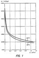
- the diagram in fig. 1 gives the flow rate in m3 / h plotted on the abscissa as a function of the time differences, the unit of which is here 100 ⁇ s, plotted on the ordinate.
- the time differences necessary for cooling a probe heated to 15 ° C above the temperature of the fluid have been plotted so that it reaches a second temperature threshold closer to the temperature of the fluid.
- This diagram clearly shows that the measured time difference does not only depend on the flow rate but also, in a non negligible way , of the temperature of the fluid, from where the important imprecision which results from it by using exponential equations.
- a table is established comprising n columns of increasing temperatures, for example for a hot water circuit every 10 ° C between 20 ° C and 90 ° C, and x lines of increasing flows between 0 and 1.1 m 3 / h with invervals of 0.1 m 3 / h, in which we carry the reference values of the characteristic time differences measured to go from temperatures T i to T 2 .
- This table constitutes the reference.
- the zero flow in this table allows a calibration of the probe, since it suffices to measure the cooling time of this probe between temperatures Ti and T 2 in a fluid of known temperature and to compare this time with that of the reference table .
- a correction factor can thus be determined to take account of the difference between the reference value and that of the probe.
- the table above illustrates, by way of example, the time differences for two temperatures of the fluid as a function of the flow rates ranging from 0 to 1.1 m 3 / h. It is obvious that this table can be completed for other temperatures, the principle of determining the flow rate remaining the same.
- the value of the time difference unit which is here 100 ps is determined according to the desired precision. As the slope of the curves decreases sharply when the flow increases, this time unit is chosen to have at least one unit per% of flow at the highest flow and at the lowest temperature where the sensitivity is the lowest. As seen in the table at 30 ° C, between the flows 1.0 and 1.1 m 3 / h there are 15 time units, ie 1.5 units per% of flow.
- the exploitation of this table is carried out using a double interpolation.
- a fluid temperature of 37 ° C and a time difference of 2225 units are measured between the temperatures Ti and T 2 .
- the first operation consists in calculating the time differences for a temperature of 37 ° C.
- the second operation consists in identifying the two values framing the measured time difference and in interpolating between these two values in our example 2280 at 0.4 m 3 / h and 2214 at 0.5 m 3 / h.
- the functions are not linear as we have seen, we note that the error which can be introduced by this interpolation method is extremely small at the calculation level, taking into account the reduced intervals between the values of the table.
- the table has 12 rows and 8 columns (between 20 ° C and 90 ° C), so that there are only 96 values of four digits each to memorize, which requires low memory capacity and therefore inexpensive components, which is important in the case of domestic applications in particular.
- Degussa probes typen F 2101, Minco, type S260 PD, Heraeus, type 1 Pt 100 FKG 1030.6 or Jumo type PC 1.32 10.1.
- the dimensions of this probe are, for example, 10 x 3 x 1 (mm, L x 1 xe) and the time constant is of the order of 0.3 s in water at 0.2 m / s.
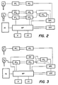
- the block diagram in FIG. 2, illustrating the application of the method to a heat meter, comprises two probes S 1 and S 2 arranged respectively in the inlet duct and in that of the outlet of a central heating circuit.
- the probe S 1 only measures the inlet temperature of the fluid, and is connected for this purpose to a source of measurement current SC 1 of 5mA which generates a heating of less than 0.05 ° C in calm water.
- a differential amplifier AD 1 amplifies the measurement signal and transmits it to an MPL multiplexer.
- the probe S 2 is double as illustrated in fig. 2.
- One of the elements of this probe is connected to a current source SC 2 which, like the source SC 1 provides a direct current of 5 mA, corresponding to a current for measuring the voltage of this probe proportional to the resistance , itself a function of the temperature of the fluid.
- the other element of this double probe S 2 is connected to a source SC 3 which supplies it alternately with a heating current of 150 mA and a measurement current of 5 mA during the period of cooling of this element by the flow of fluid.
- These two sources SC 2 and SC s are connected to two differential amplifiers AD 2 respectively AD 3 .
- the second of these amplifiers AD 3 adapts its gain from 1 to 30 depending on whether the source SC 3 is 5 mA or 150 mA corresponding to the measurement periods respectively of heating the probe element S 2 , so that the resulting gain remains constant.
- the source SCs and the amplifier AD 3 are for this purpose connected to the microprocessor MP which comprises the program fixing in particular the periodicity of the switching between the measurement current and the heating current, as well as that of the respective gains of the differential amplifier AD 3 synchronized with the current from the source SCs.
- the two differential amplifiers AD 2 , ADs are connected to another differential amplifier AD 4 , which indicates to the multiplexer MPL the value of the time interval which has elapsed for the probe element S 2 , after having been heated , goes from temperature Ti to temperature T 2 , thus providing the microprocessor with the time difference necessary for the above-mentioned interpolation calculation.
- the output of the differential amplifier AD 2 is also connected to the multiplexer MPL to indicate the temperature of the fluid at the output of the heating installation.
- the output of the multiplexer is connected to the MP microprocessor and to a 10-bit ADC analog-digital converter, also connected to the MP microprocessor whose outputs go to a D display and a CC control command.
- the entire circuit is supplied by a general supply AL.
- the CC control command is used to choose the value to be displayed on the display unit D. Since it receives the inlet and outlet temperatures and calculates the flow rate of the fluid, the microprocessor can also calculate the energy consumption in kW. It is then possible to choose one of these values to appear by choosing it using the CC control command.
- the block diagram illustrated in FIG. 3 is a variant of the previous one in which the probe S 2 has only one sensor and is therefore only supplied by the current source SC 3 , the current source SC 2 and the differential amplifier AD 2 being eliminated.
- the source connects alternately on a heating power of 150 mA and on a measurement power of 5 mA.
- a new cycle is preceded by the measurement of the temperature of the fluid and its storage in an analog memory MA replacing the second sensor and keeping the voltage value proportional to the resistance of probe S 2 characteristic of the fluid temperature.
- This memory is connected on the one hand to the microprocessor MP, on the other hand to the differential amplifier AD 4 and to the multiplexer MPL.
- the rest of the circuit is similar to that of fig. 2.
Landscapes
- Physics & Mathematics (AREA)
- Fluid Mechanics (AREA)
- General Physics & Mathematics (AREA)
- Measuring Volume Flow (AREA)
- Flow Control (AREA)
- Details Of Flowmeters (AREA)
- Transition And Organic Metals Composition Catalysts For Addition Polymerization (AREA)
Claims (4)
Priority Applications (1)
| Application Number | Priority Date | Filing Date | Title |
|---|---|---|---|
| AT87810199T ATE51295T1 (de) | 1986-04-08 | 1987-04-02 | Verfahren zur bestimmung des durchflusses eines fluids. |
Applications Claiming Priority (2)
| Application Number | Priority Date | Filing Date | Title |
|---|---|---|---|
| CH1369/86A CH667919A5 (fr) | 1986-04-08 | 1986-04-08 | Procede pour determiner le debit d'un fluide. |
| CH1369/86 | 1986-04-08 |
Publications (2)
| Publication Number | Publication Date |
|---|---|
| EP0241424A1 EP0241424A1 (de) | 1987-10-14 |
| EP0241424B1 true EP0241424B1 (de) | 1990-03-21 |
Family
ID=4208805
Family Applications (1)
| Application Number | Title | Priority Date | Filing Date |
|---|---|---|---|
| EP87810199A Expired - Lifetime EP0241424B1 (de) | 1986-04-08 | 1987-04-02 | Verfahren zur Bestimmung des Durchflusses eines Fluids |
Country Status (8)
| Country | Link |
|---|---|
| US (1) | US4770037A (de) |
| EP (1) | EP0241424B1 (de) |
| JP (1) | JPS62259017A (de) |
| AT (1) | ATE51295T1 (de) |
| AU (1) | AU7117087A (de) |
| CH (1) | CH667919A5 (de) |
| DE (1) | DE3762005D1 (de) |
| DK (1) | DK175987A (de) |
Families Citing this family (13)
| Publication number | Priority date | Publication date | Assignee | Title |
|---|---|---|---|---|
| DE3639666A1 (de) * | 1986-11-20 | 1988-06-01 | Draegerwerk Ag | Verfahren zur bestimmung einer messgroesse eines stroemenden mediums und messschaltung hierzu |
| US6965815B1 (en) | 1987-05-27 | 2005-11-15 | Bilboa Instruments, Inc. | Spa control system |
| US5361215A (en) | 1987-05-27 | 1994-11-01 | Siege Industries, Inc. | Spa control system |
| NL9201906A (nl) * | 1992-11-02 | 1994-06-01 | Huiberts Albertus T | Werkwijze en inrichting voor het meten van het debiet van een mediumstroom. |
| US5764539A (en) * | 1994-01-21 | 1998-06-09 | Novartis Nutrition Ag | Non-invasive system and method for a fluid flow monitoring system |
| DE19504496C2 (de) * | 1994-02-28 | 2000-05-31 | Ifm Electronic Gmbh | Verfahren zur Überwachung der Strömung strömender Medien |
| GB9612096D0 (en) * | 1996-06-10 | 1996-08-14 | Secr Defence | Temperature probe |
| KR20010031132A (ko) * | 1997-10-15 | 2001-04-16 | 미야무라 심뻬이 | 유량센서, 유량계 및 액체토출기기의 토출량 제어장치 |
| US6596059B1 (en) * | 2000-09-12 | 2003-07-22 | Skyline Products, Inc. | Automated filter changing device and method |
| WO2006135293A1 (en) * | 2005-06-16 | 2006-12-21 | St. Jude Medical Ab | Flow sensor and method for measuring the flow of a body fluid |
| US8348731B2 (en) * | 2005-08-05 | 2013-01-08 | Wilmington Research And Development Corporation | Adaptive cooling method for computer rack enclosure |
| US9151152B2 (en) | 2012-06-20 | 2015-10-06 | Schlumberger Technology Corporation | Thermal optical fluid composition detection |
| EP3544489A1 (de) * | 2016-11-28 | 2019-10-02 | Koninklijke Philips N.V. | Durchflussmesser und verfahren zur bestimmung einer durchflussmenge |
Family Cites Families (6)
| Publication number | Priority date | Publication date | Assignee | Title |
|---|---|---|---|---|
| DE1548614B2 (de) * | 1965-06-28 | 1976-05-20 | C al vet, Pierre Jean Felix, Meudon (Frankreich) | Verfahren und vorrichtung zur messung von zustandsgroessen von gasen und fluessigkeiten |
| FR1577448A (de) * | 1968-05-22 | 1969-08-08 | ||
| US3719083A (en) * | 1970-04-01 | 1973-03-06 | Nat Res Dev | Flowmeters |
| JPS5543447A (en) * | 1978-09-22 | 1980-03-27 | Hitachi Ltd | Hot-wire type flow rate measuring device |
| JPS58501094A (ja) * | 1981-07-13 | 1983-07-07 | バテル メモリアル インステイチユ−ト | 流体中に浸漬された探査子の熱交換と関連する該流体の少なくとも1つの瞬時的パラメ−タを算定する方法及び該方法を実行するための装置 |
| US4402012A (en) * | 1981-11-16 | 1983-08-30 | General Electric Company | Two-dimensional digital linear interpolation system |
-
1986
- 1986-04-08 CH CH1369/86A patent/CH667919A5/fr not_active IP Right Cessation
-
1987
- 1987-04-02 AT AT87810199T patent/ATE51295T1/de not_active IP Right Cessation
- 1987-04-02 EP EP87810199A patent/EP0241424B1/de not_active Expired - Lifetime
- 1987-04-02 DE DE8787810199T patent/DE3762005D1/de not_active Expired - Lifetime
- 1987-04-07 JP JP62083936A patent/JPS62259017A/ja active Pending
- 1987-04-07 DK DK175987A patent/DK175987A/da not_active Application Discontinuation
- 1987-04-07 US US07/035,487 patent/US4770037A/en not_active Expired - Fee Related
- 1987-04-08 AU AU71170/87A patent/AU7117087A/en not_active Withdrawn
Also Published As
| Publication number | Publication date |
|---|---|
| DK175987A (da) | 1987-10-09 |
| DK175987D0 (da) | 1987-04-07 |
| AU7117087A (en) | 1987-10-15 |
| JPS62259017A (ja) | 1987-11-11 |
| ATE51295T1 (de) | 1990-04-15 |
| CH667919A5 (fr) | 1988-11-15 |
| EP0241424A1 (de) | 1987-10-14 |
| US4770037A (en) | 1988-09-13 |
| DE3762005D1 (de) | 1990-04-26 |
Similar Documents
| Publication | Publication Date | Title |
|---|---|---|
| WO1983000227A1 (en) | Method and device for analyzing a fluid by means of a heated probe | |
| EP0241424A1 (de) | Verfahren zur Bestimmung des Durchflusses eines Fluids | |
| AU670162B2 (en) | Method and apparatus for measuring the flow rate of a medium flow | |
| FR2552876A1 (fr) | Systeme thermique de mesure de niveau de liquide | |
| JP3204673B2 (ja) | 流体計測 | |
| JP5312579B2 (ja) | 熱交換器内のファウリングの検出及び/又は測定のための方法及び装置 | |
| FR2514497A1 (fr) | Dispositif de detection numerique de niveau par fil chaud | |
| US4036053A (en) | Methods of and means for measuring liquid flow | |
| CN113176013B (zh) | 一种用于热流测试的薄膜热电阻热流计和同轴热电偶的标定方法 | |
| FR2993981A1 (fr) | Calorimetre auto-etalonnable par substitution electrique | |
| RU2145063C1 (ru) | Способ учета расхода тепловой энергии отопительного прибора и устройство для его осуществления | |
| JP2010101841A (ja) | 付着物検出ユニット及び検出装置 | |
| FR2558954A1 (fr) | Calorimetre | |
| Bernhardsgrütter et al. | Robust and flexible thermal sensor using the 3-omega-method to investigate thermal properties of fluids | |
| FR2633048A1 (fr) | Procede d'etalonnage automatique en ligne d'un capteur de mesure de la concentration d'une espece electrochimique dissoute en phase liquide | |
| EP0852331A1 (de) | Verfahren und Anordnung zur Messung des Volumenkoeffizienten von Wärmeverlusten eines elektrisch gheizten Raumes | |
| FR2739931A1 (fr) | Procede et dispositif pour mesurer le coefficient volumique de deperdition thermique d'un local chauffe electriquement | |
| CH628734A5 (en) | Meter of the quantities of heat dissipated in individual heating installations with radiators supplied by a common source | |
| FR2536854A1 (fr) | Dispositif de mesure de la temperature | |
| WO1992008956A1 (fr) | Appareil pour la mesure de proprietes physiques de fluides | |
| CH507508A (fr) | Procédé thermique de mesure de débit et débitmètre pour la mise en oeuvre de ce procédé | |
| RSR | wire, 0.762 mm in diameter. The resistance of Evanohm wire is 286.7 ohms per | |
| WO2017148940A1 (fr) | Procede et dispositif de mesure de proprietes thermo-physiques d'un milieu | |
| RU2077023C1 (ru) | Способ измерения электрических и неэлектрических величин | |
| FR2530337A1 (fr) | Dispositif pour la mesure directe de l'energie thermique transmise |
Legal Events
| Date | Code | Title | Description |
|---|---|---|---|
| PUAI | Public reference made under article 153(3) epc to a published international application that has entered the european phase |
Free format text: ORIGINAL CODE: 0009012 |
|
| AK | Designated contracting states |
Kind code of ref document: A1 Designated state(s): AT BE CH DE ES FR GB GR IT LI LU NL SE |
|
| 17P | Request for examination filed |
Effective date: 19880321 |
|
| 17Q | First examination report despatched |
Effective date: 19890721 |
|
| GRAA | (expected) grant |
Free format text: ORIGINAL CODE: 0009210 |
|
| AK | Designated contracting states |
Kind code of ref document: B1 Designated state(s): AT BE CH DE ES FR GB GR IT LI LU NL SE |
|
| PG25 | Lapsed in a contracting state [announced via postgrant information from national office to epo] |
Ref country code: IT Free format text: LAPSE BECAUSE OF FAILURE TO SUBMIT A TRANSLATION OF THE DESCRIPTION OR TO PAY THE FEE WITHIN THE PRE;WARNING: LAPSES OF ITALIAN PATENTS WITH EFFECTIVE DATE BEFORE 2007 MAY HAVE OCCURRED AT ANY TIME BEFORE 2007. THE CORRECT EFFECTIVE DATE MAY BE DIFFERENT FROM THE ONE RECORDED.SCRIBED TIME-LIMIT Effective date: 19900321 Ref country code: SE Effective date: 19900321 Ref country code: NL Effective date: 19900321 Ref country code: GR Free format text: LAPSE BECAUSE OF FAILURE TO SUBMIT A TRANSLATION OF THE DESCRIPTION OR TO PAY THE FEE WITHIN THE PRESCRIBED TIME-LIMIT Effective date: 19900321 Ref country code: GB Effective date: 19900321 Ref country code: AT Effective date: 19900321 |
|
| REF | Corresponds to: |
Ref document number: 51295 Country of ref document: AT Date of ref document: 19900415 Kind code of ref document: T |
|
| REF | Corresponds to: |
Ref document number: 3762005 Country of ref document: DE Date of ref document: 19900426 |
|
| PG25 | Lapsed in a contracting state [announced via postgrant information from national office to epo] |
Ref country code: BE Effective date: 19900430 Ref country code: LU Free format text: LAPSE BECAUSE OF NON-PAYMENT OF DUE FEES Effective date: 19900430 |
|
| PGFP | Annual fee paid to national office [announced via postgrant information from national office to epo] |
Ref country code: CH Payment date: 19900626 Year of fee payment: 4 |
|
| PG25 | Lapsed in a contracting state [announced via postgrant information from national office to epo] |
Ref country code: ES Free format text: LAPSE BECAUSE OF FAILURE TO SUBMIT A TRANSLATION OF THE DESCRIPTION OR TO PAY THE FEE WITHIN THE PRESCRIBED TIME-LIMIT Effective date: 19900702 |
|
| NLV1 | Nl: lapsed or annulled due to failure to fulfill the requirements of art. 29p and 29m of the patents act | ||
| GBV | Gb: ep patent (uk) treated as always having been void in accordance with gb section 77(7)/1977 [no translation filed] | ||
| BERE | Be: lapsed |
Owner name: BATTELLE MEMORIAL INSTITUTE Effective date: 19900430 |
|
| PG25 | Lapsed in a contracting state [announced via postgrant information from national office to epo] |
Ref country code: DE Effective date: 19910101 |
|
| PLBE | No opposition filed within time limit |
Free format text: ORIGINAL CODE: 0009261 |
|
| STAA | Information on the status of an ep patent application or granted ep patent |
Free format text: STATUS: NO OPPOSITION FILED WITHIN TIME LIMIT |
|
| PG25 | Lapsed in a contracting state [announced via postgrant information from national office to epo] |
Ref country code: FR Effective date: 19910228 |
|
| 26N | No opposition filed | ||
| REG | Reference to a national code |
Ref country code: FR Ref legal event code: ST |
|
| PG25 | Lapsed in a contracting state [announced via postgrant information from national office to epo] |
Ref country code: LI Effective date: 19910430 Ref country code: CH Effective date: 19910430 |
|
| REG | Reference to a national code |
Ref country code: CH Ref legal event code: PL |
|
| PG25 | Lapsed in a contracting state [announced via postgrant information from national office to epo] |
Ref country code: FR Effective date: 19900430 |