EP0241280A2 - A roll for use in determining the shape of metal strip - Google Patents
A roll for use in determining the shape of metal strip Download PDFInfo
- Publication number
- EP0241280A2 EP0241280A2 EP87303059A EP87303059A EP0241280A2 EP 0241280 A2 EP0241280 A2 EP 0241280A2 EP 87303059 A EP87303059 A EP 87303059A EP 87303059 A EP87303059 A EP 87303059A EP 0241280 A2 EP0241280 A2 EP 0241280A2
- Authority
- EP
- European Patent Office
- Prior art keywords
- arbor
- roll
- ring structure
- ring
- strip
- Prior art date
- Legal status (The legal status is an assumption and is not a legal conclusion. Google has not performed a legal analysis and makes no representation as to the accuracy of the status listed.)
- Withdrawn
Links
Images


Classifications
-
- G—PHYSICS
- G01—MEASURING; TESTING
- G01L—MEASURING FORCE, STRESS, TORQUE, WORK, MECHANICAL POWER, MECHANICAL EFFICIENCY, OR FLUID PRESSURE
- G01L5/00—Apparatus for, or methods of, measuring force, work, mechanical power, or torque, specially adapted for specific purposes
- G01L5/04—Apparatus for, or methods of, measuring force, work, mechanical power, or torque, specially adapted for specific purposes for measuring tension in flexible members, e.g. ropes, cables, wires, threads, belts or bands
- G01L5/045—Apparatus for, or methods of, measuring force, work, mechanical power, or torque, specially adapted for specific purposes for measuring tension in flexible members, e.g. ropes, cables, wires, threads, belts or bands for measuring the tension across the width of a band-shaped flexible member
-
- B—PERFORMING OPERATIONS; TRANSPORTING
- B21—MECHANICAL METAL-WORKING WITHOUT ESSENTIALLY REMOVING MATERIAL; PUNCHING METAL
- B21B—ROLLING OF METAL
- B21B38/00—Methods or devices for measuring, detecting or monitoring specially adapted for metal-rolling mills, e.g. position detection, inspection of the product
- B21B38/02—Methods or devices for measuring, detecting or monitoring specially adapted for metal-rolling mills, e.g. position detection, inspection of the product for measuring flatness or profile of strips
-
- G—PHYSICS
- G01—MEASURING; TESTING
- G01B—MEASURING LENGTH, THICKNESS OR SIMILAR LINEAR DIMENSIONS; MEASURING ANGLES; MEASURING AREAS; MEASURING IRREGULARITIES OF SURFACES OR CONTOURS
- G01B5/00—Measuring arrangements characterised by the use of mechanical techniques
- G01B5/20—Measuring arrangements characterised by the use of mechanical techniques for measuring contours or curvatures
- G01B5/207—Measuring arrangements characterised by the use of mechanical techniques for measuring contours or curvatures using a plurality of fixed, simultaneously operating transducers
-
- G—PHYSICS
- G01—MEASURING; TESTING
- G01B—MEASURING LENGTH, THICKNESS OR SIMILAR LINEAR DIMENSIONS; MEASURING ANGLES; MEASURING AREAS; MEASURING IRREGULARITIES OF SURFACES OR CONTOURS
- G01B7/00—Measuring arrangements characterised by the use of electric or magnetic techniques
- G01B7/28—Measuring arrangements characterised by the use of electric or magnetic techniques for measuring contours or curvatures
- G01B7/287—Measuring arrangements characterised by the use of electric or magnetic techniques for measuring contours or curvatures using a plurality of fixed, simultaneously operating transducers
Definitions
- the resulting strip has a satisfactory shape, that is, that the metal strip will lie flat on a flat surface. Satisfactory shape is obtained by ensuring that the tension in the strip immediately it leaves the mill after rolling is substantially uniform across the width of the strip.
- a shapemeter sold under the Registered Trade Mark VIDIMON consists of a roll rotatable about its longitudinal axis and which bears against the underside of the moving strip.
- the roll comprises a number of individual rollers arranged side-by-side in the direction of the width of the strip, with each individual roller having means for detecting the pressure applied to the roller by the metal strip.
- An object of the present invention is to provide a roll for use in determining the tension in metal strip moving in the direction of its length which is cheaper to manufacture than shapemeter rolls known heretofore.
- a roll for use in determining the tension in metal strip moving in the direction of its length comprises an elongate metal arbor mounted for rotation about its longitudinal axis, an annular ring structure fitted around the arbor but separated therefrom by an elastic body which permits displacement of the ring structure in the direction towards and away from the arbor and means for detecting displacement of the ring structure when the moving strip is wrapped around part of the periphery thereof.
- a roll for use in determining the tension in metal strip moving in the direction of its length comprises an elongate metal arbor mounted for rotation about its longitudinal axis, a plurality of annular ring structures fitted side-by-side around the arbor and each separated therefrom by an elastic body which permits displacement of the ring structure in the direction towards and away from the arbor and each ring structure having means for detecting displacement of the ring structure when the moving strip is wrapped around part of the periphery thereof.
- the movement of the strip causes the arbor to rotate about its longitudinal axis but, at the same time, the tension in the strip causes the engaged part of the annular ring to be displaced in the direction towards the longitudinal axis of the arbor.
- an indication can be obtained of the tension in the strip.
- the or each elastic body may be of plastics material, such as polyurethane.
- the plastics material may fill the space between the arbor and the ring or it may be in the form of an annular disc, the outside of which engages the ring and the inside of which engages the arbor.
- the or each annular ring is separated from a further ring mounted on the arbor by a web and the web constitutes the elastic body.
- the displacement of the sleeve may be detected by either a contacting or a non-contacting detecting device which is located outside the ring opposite to that part of the periphery against which the strip is wrapped so that the displacement of the ring is towards and away from the device.
- the detecting device which is fixed relative to the axis of the arbor produces an output signal representative of the position of the ring relative to the device.
- the detecting device may be a load sensitive device which is mounted either on the ring or on the arbor and is embedded in the plastics material. This detecting device serves to detect the displacement of the ring by detecting variations in the load which is applied to the plastics material when the ring is displaced.
- an elongate rigid metal arbor 1 is mounted in bearings (not shown) which permit the arbor to rotate about its longitudinal axis.
- a plurality of rigid annular metal rings 3 are arranged side-by-side around the arbor 1 but they are spaced apart from the arbor.
- the rings are normally coaxial with the arbor 1 and are separated thereform by individual bodies 5 of elastically deformable plastics material, such as polyurethane.
- each ring 3 has a separate body of plastics material 5, whereas, in an alternative form of the invention, a single sleeve of deformable plastics material is positioned between the rings and the arbor.
- the bodies of plastics material permit the rings to be displaced relative to the arbor and, because of the stiffness of the plastics materials, there is no permanent distortion of the plastics material as the rings are displaced with respect to the arbor.
- the detecting devices 7 may be mounted on the arbor, as shown in Figures 1 and 2, with their electrical connections 9 extending through radial bores in the arbor into a central bore 11 extending coaxial of the arbor. Alternatively, the detecting devices may be mounted on the rings.
- the detecting devices 7 which conveniently take the form of load cells or strain gauges, are mounted in the desired side-by-side position on the surface of the arbor with their electrical leads extending through the bores to the axial bore of the arbor.
- the load cells or strain gauges may be mounted in a row along the length of the arbor or they may be arranged in helical manner around the periphery of the arbor.
- the arbor with the load cells/strain gauges mounted on it is held in a jig with the rings 3 surrounding it and polyurethane material is cast into the space between the rings and the arbor to embed the detecting devices 7.
- the outer surface of the rings 3 is ground so that the surface is concentric with the axis of the arbor.
- the electrical signals from the detecting devices are taken by the leads extending through the bore of the arbor and the leads can rotate with the arbor but slip rings (not shown) could be used to transfer the signals from the leads to external recorders. Alternatively, slip rings could be avoided and other forms of telemetry equipment could be used.
- the signals from the detecting device are converted into optical signals which are received by light sensitive devices.
- each detecting device is provided for each of the rings 3, then one signal is received from each detecting device for each revolution of the roll.
- a plurality of devices could be mounted in angularly spaced apart relation for each of the rings 3.
- the rings 3 are separated from the arbor 1 by individual annular bodies 5 of resilient plastics material but, in this embodiment of the invention, the detecting devices are not embedded in the plastics material but are positioned beneath the roll on a fixed surface 15 which is a predetermined distance below the axis of the arbor.
- Each ring has its own detector 17 and the detectors may be of several different forms. Whatever form the detector takes, however, its purpose is to detect the displacement of its associated ring in the direction at right angles to the longitudinal axis of the arbor as the strip material wraps around part of the periphery of the rings 3.
- the detectors 17 are positioned beneath the roller substantially in alignment with the downwardly extending forces on the rings when the strip is in contact with them.
- the downwardly applied forces on the top of the ring causes the bottom of the ring to move towards the detector.
- each of the rings 23 has an inwardly extending web 25.
- This web engages with the upper side of an annular body 27 of plastics material which is mounted on the arbor and the area of contact between the web 25 and the body of plastics material is less than the area of contact between the body of plastics material and the arbor.
- forces applied to each ring 23 by the strip engaging with it are directed through the narrow web to the plastics material, thus allowing greater movement of the ring towards and away from the axis of the arbor as compared with the arrangement shown in Figure 3, assuming that the same plastics material is employed.
- each annular ring 33 has a groove formed on its inner surface and a disc 35 of resilient plastics material has its outer edge inserted into the groove to retain the disc within the ring and its inner surface mounted on the arbor.
- FIG. 6 A similar construction is shown in Figure 6 except that a roller or tapered roller bearing 36 is fitted on to the outside of each annular ring 33 to form a ring structure.
- the inner race of each bearing is fast on the ring 33 and the metal strip is in engagement with the outer races of the bearings. Movement of the strip causes the outer races to rotate and there is very little scuffing between the underside of the strip and the outer races.
- each ring 43 is integral with an inner ring 45 and a connecting web 47.
- the rings are mounted side-by-side on the arbor 1 and the webs 47 have their cross-section reduced by a plurality of annular grooves 49 cut in them.
- the web 47 thus serves as the elastically deformable body between the ring 43 and the arbor 1.
- An end support 51 prevents sideways deflection of the rings when the rings are urged into engagement with the underside of the moving strip, and the forces in the strip push the engaged portion of rings 43 downwardly towards the arbor 1 and the web 47 permits the displacement of the rings 43 towards the arbor.
- the downward displacement of the rings 43 is detected by detecting devices 17 positioned beneath the roll.
- the detector may be located at one position, conveniently immediately below the ring in a vertical plane containing the axis of the arbor, or a number of detectors may be positioned around the rings so that any distortion of the rings can be detected.
- the detector 17 shown in the drawings may be of the contacting type where a part of the detector is permanently in contact with the ring, or it may be of the non-contacting type where the detector is always spaced from the ring, but where the separation between them varies as the ring is displaced.
- the transducer or detector is held in contacting relation with the outer surface of the ring by way of a roller or a similar bearing.
- the detector may take the form of a load cell which is mounted vertically below the ring and in contact with the outer surface of the ring by way of a bearing.
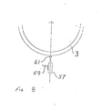
- FIG. 7 an arrangement is shown in Figure 7 where a position transducer 57 is held rigidly by way of a bracket 59 beneath the ring 3 and in the vertical plane containing the axis of the arbor.
- a plunger 61 extends from the transducer close to the ring and there is an air cushion formed between the head of the plunger and the adjacent surface of the ring.
- detector such as an eddy current displacement transducer or a laser operated transducer where a laser beam is directed towards a reflector and, depending upon the position of the ring, the laser beam is reflected at a varied angle.
- Such a laser device is well known and is offered for sale by MEA INC., 2600, American Lane, Elk Grove Village, Illinois 60007, U.S.A.
Landscapes
- Physics & Mathematics (AREA)
- General Physics & Mathematics (AREA)
- Engineering & Computer Science (AREA)
- Mechanical Engineering (AREA)
- Force Measurement Appropriate To Specific Purposes (AREA)
- A Measuring Device Byusing Mechanical Method (AREA)
- Length Measuring Devices With Unspecified Measuring Means (AREA)
Abstract
Description
- It is most important when rolling metal strip that the resulting strip has a satisfactory shape, that is, that the metal strip will lie flat on a flat surface. Satisfactory shape is obtained by ensuring that the tension in the strip immediately it leaves the mill after rolling is substantially uniform across the width of the strip.
- It is well known to employ a shapemeter downstream of a rolling mill stand to measure tension across the width of the strip. As a result of the output from the shapemeter, steps may be taken to effect changes in the shape of the rolls of the mill and/or to adjust the roll gap at one side of the mill relative to the gap at the other side in order to improve the shape.
- A shapemeter sold under the Registered Trade Mark VIDIMON consists of a roll rotatable about its longitudinal axis and which bears against the underside of the moving strip. The roll comprises a number of individual rollers arranged side-by-side in the direction of the width of the strip, with each individual roller having means for detecting the pressure applied to the roller by the metal strip.
- An object of the present invention is to provide a roll for use in determining the tension in metal strip moving in the direction of its length which is cheaper to manufacture than shapemeter rolls known heretofore.
- According to a first aspect of the present invention, a roll for use in determining the tension in metal strip moving in the direction of its length comprises an elongate metal arbor mounted for rotation about its longitudinal axis, an annular ring structure fitted around the arbor but separated therefrom by an elastic body which permits displacement of the ring structure in the direction towards and away from the arbor and means for detecting displacement of the ring structure when the moving strip is wrapped around part of the periphery thereof.
- According to a second aspect of the present invention, a roll for use in determining the tension in metal strip moving in the direction of its length comprises an elongate metal arbor mounted for rotation about its longitudinal axis, a plurality of annular ring structures fitted side-by-side around the arbor and each separated therefrom by an elastic body which permits displacement of the ring structure in the direction towards and away from the arbor and each ring structure having means for detecting displacement of the ring structure when the moving strip is wrapped around part of the periphery thereof.
- When the moving strip is in contact with the annular ring, the movement of the strip causes the arbor to rotate about its longitudinal axis but, at the same time, the tension in the strip causes the engaged part of the annular ring to be displaced in the direction towards the longitudinal axis of the arbor. By detecting this displacement of the ring, an indication can be obtained of the tension in the strip. When a plurality of rings are arranged side-by-side on an arbor, the tension across the width of the strip can be determined by detecting the relative displacement of each annular ring relative to the arbor.
- The or each elastic body may be of plastics material, such as polyurethane. The plastics material may fill the space between the arbor and the ring or it may be in the form of an annular disc, the outside of which engages the ring and the inside of which engages the arbor.
- In an alternative form of the invention, the or each annular ring is separated from a further ring mounted on the arbor by a web and the web constitutes the elastic body.
- The displacement of the sleeve may be detected by either a contacting or a non-contacting detecting device which is located outside the ring opposite to that part of the periphery against which the strip is wrapped so that the displacement of the ring is towards and away from the device. In this way, the detecting device which is fixed relative to the axis of the arbor produces an output signal representative of the position of the ring relative to the device.
- In an alternative form of the invention, the detecting device may be a load sensitive device which is mounted either on the ring or on the arbor and is embedded in the plastics material. This detecting device serves to detect the displacement of the ring by detecting variations in the load which is applied to the plastics material when the ring is displaced.
- In order that the invention may be more readily understood, it will now be described, by way of example only, with reference to the accompanying drawings, in which:-
- Figure 1 is a side elevation, partly in section, of part of a roll for use in determining the tension in metal strip in accordance with the present invention;
- Figure 2 is an end elevation on the line II-II of Figure 1;
- Figures 3, 4, 5 and 6 are side elevations, partly in section, of a roll for use in determining the tension in metal strip in accordance with alternative embodiments of the invention;
- Figure 7 is a sectional side elevation of part of a roll in accordance with a still further embodiment of the invention; and
- Figure 8 shows diagrammatically a form of detector which could be employed in the embodiments of the invention shown in Figures 3 to 7.
- In order to determine the shape of metal strip moving in the direction of its length, an investigation is made into the tension across the width of the strip. To this end, the metal strip is wrapped around part of the periphery of a roll which is urged against the underside of the metal strip.
- Referring to Figures 1 and 2, an elongate
rigid metal arbor 1 is mounted in bearings (not shown) which permit the arbor to rotate about its longitudinal axis. A plurality of rigidannular metal rings 3 are arranged side-by-side around thearbor 1 but they are spaced apart from the arbor. The rings are normally coaxial with thearbor 1 and are separated thereform byindividual bodies 5 of elastically deformable plastics material, such as polyurethane. In the arrangement shown in Figures 1 and 2, eachring 3 has a separate body ofplastics material 5, whereas, in an alternative form of the invention, a single sleeve of deformable plastics material is positioned between the rings and the arbor. - In use, movement of the strip in the direction of its length causes the roll to rotate about its longitudinal axis and the strip applies forces to each
annular ring 3. The forces have a component which displaces the sleeve downwardly with respect to the arbor so that the axis of the sleeve is no longer coincident with that of the arbor. The forces applied to the rings are a measure of the tension in that part of the strip which engages with each ring and, consequently, the displacement of the rings is an indication of the tension across the width of the strip. - The bodies of plastics material permit the rings to be displaced relative to the arbor and, because of the stiffness of the plastics materials, there is no permanent distortion of the plastics material as the rings are displaced with respect to the arbor.
- Between the arbor and each
ring 3 there is anindividual detecting device 7 which detects a variation in load applied to the plastics material as thering 3 is displaced. Thedetecting devices 7 may be mounted on the arbor, as shown in Figures 1 and 2, with their electrical connections 9 extending through radial bores in the arbor into a central bore 11 extending coaxial of the arbor. Alternatively, the detecting devices may be mounted on the rings. - To construct the roll, the
detecting devices 7, which conveniently take the form of load cells or strain gauges, are mounted in the desired side-by-side position on the surface of the arbor with their electrical leads extending through the bores to the axial bore of the arbor. The load cells or strain gauges may be mounted in a row along the length of the arbor or they may be arranged in helical manner around the periphery of the arbor. The arbor with the load cells/strain gauges mounted on it is held in a jig with therings 3 surrounding it and polyurethane material is cast into the space between the rings and the arbor to embed the detectingdevices 7. Finally, the outer surface of therings 3 is ground so that the surface is concentric with the axis of the arbor. - The electrical signals from the detecting devices are taken by the leads extending through the bore of the arbor and the leads can rotate with the arbor but slip rings (not shown) could be used to transfer the signals from the leads to external recorders. Alternatively, slip rings could be avoided and other forms of telemetry equipment could be used.
- In an alternative embodiment, the signals from the detecting device are converted into optical signals which are received by light sensitive devices.
- If one detecting device is provided for each of the
rings 3, then one signal is received from each detecting device for each revolution of the roll. However, a plurality of devices could be mounted in angularly spaced apart relation for each of therings 3. - In the embodiment of the invention shown in Figure 3, the
rings 3 are separated from thearbor 1 by individualannular bodies 5 of resilient plastics material but, in this embodiment of the invention, the detecting devices are not embedded in the plastics material but are positioned beneath the roll on afixed surface 15 which is a predetermined distance below the axis of the arbor. Each ring has itsown detector 17 and the detectors may be of several different forms. Whatever form the detector takes, however, its purpose is to detect the displacement of its associated ring in the direction at right angles to the longitudinal axis of the arbor as the strip material wraps around part of the periphery of therings 3. Clearly, therefore, assuming that the strip material wraps around the upper part of the periphery of the roller shown in Figure 3, thedetectors 17 are positioned beneath the roller substantially in alignment with the downwardly extending forces on the rings when the strip is in contact with them. The downwardly applied forces on the top of the ring causes the bottom of the ring to move towards the detector. - In the embodiment of the invention shown in Figure 4, each of the
rings 23 has an inwardly extendingweb 25. This web engages with the upper side of anannular body 27 of plastics material which is mounted on the arbor and the area of contact between theweb 25 and the body of plastics material is less than the area of contact between the body of plastics material and the arbor. In this way, forces applied to eachring 23 by the strip engaging with it are directed through the narrow web to the plastics material, thus allowing greater movement of the ring towards and away from the axis of the arbor as compared with the arrangement shown in Figure 3, assuming that the same plastics material is employed. - In the arrangement shown in Figure 5, each
annular ring 33 has a groove formed on its inner surface and adisc 35 of resilient plastics material has its outer edge inserted into the groove to retain the disc within the ring and its inner surface mounted on the arbor. - A similar construction is shown in Figure 6 except that a roller or tapered roller bearing 36 is fitted on to the outside of each
annular ring 33 to form a ring structure. The inner race of each bearing is fast on thering 33 and the metal strip is in engagement with the outer races of the bearings. Movement of the strip causes the outer races to rotate and there is very little scuffing between the underside of the strip and the outer races. - In an alternative embodiment of the invention, as shown in Figure 6, each ring 43 is integral with an
inner ring 45 and a connecting web 47. The rings are mounted side-by-side on thearbor 1 and the webs 47 have their cross-section reduced by a plurality ofannular grooves 49 cut in them. The web 47 thus serves as the elastically deformable body between the ring 43 and thearbor 1. - An
end support 51 prevents sideways deflection of the rings when the rings are urged into engagement with the underside of the moving strip, and the forces in the strip push the engaged portion of rings 43 downwardly towards thearbor 1 and the web 47 permits the displacement of the rings 43 towards the arbor. The downward displacement of the rings 43 is detected by detectingdevices 17 positioned beneath the roll. The detector may be located at one position, conveniently immediately below the ring in a vertical plane containing the axis of the arbor, or a number of detectors may be positioned around the rings so that any distortion of the rings can be detected. - The
detector 17 shown in the drawings may be of the contacting type where a part of the detector is permanently in contact with the ring, or it may be of the non-contacting type where the detector is always spaced from the ring, but where the separation between them varies as the ring is displaced. When a contact method is employed, the transducer or detector is held in contacting relation with the outer surface of the ring by way of a roller or a similar bearing. Similarly, the detector may take the form of a load cell which is mounted vertically below the ring and in contact with the outer surface of the ring by way of a bearing. - As an example of the type of
detector 17, an arrangement is shown in Figure 7 where aposition transducer 57 is held rigidly by way of abracket 59 beneath thering 3 and in the vertical plane containing the axis of the arbor. A plunger 61 extends from the transducer close to the ring and there is an air cushion formed between the head of the plunger and the adjacent surface of the ring. - Other forms of detector may be employed, such as an eddy current displacement transducer or a laser operated transducer where a laser beam is directed towards a reflector and, depending upon the position of the ring, the laser beam is reflected at a varied angle.
- Such a laser device is well known and is offered for sale by MEA INC., 2600, American Lane, Elk Grove Village, Illinois 60007, U.S.A.
Claims (16)
Applications Claiming Priority (4)
| Application Number | Priority Date | Filing Date | Title |
|---|---|---|---|
| GB868608763A GB8608763D0 (en) | 1986-04-10 | 1986-04-10 | Roll for determining shape of metal strip |
| GB8608763 | 1986-04-10 | ||
| GB8613355 | 1986-06-03 | ||
| GB868613355A GB8613355D0 (en) | 1986-06-03 | 1986-06-03 | Roll |
Publications (2)
| Publication Number | Publication Date |
|---|---|
| EP0241280A2 true EP0241280A2 (en) | 1987-10-14 |
| EP0241280A3 EP0241280A3 (en) | 1990-04-11 |
Family
ID=26290610
Family Applications (1)
| Application Number | Title | Priority Date | Filing Date |
|---|---|---|---|
| EP87303059A Withdrawn EP0241280A3 (en) | 1986-04-10 | 1987-04-08 | A roll for use in determining the shape of metal strip |
Country Status (1)
| Country | Link |
|---|---|
| EP (1) | EP0241280A3 (en) |
Cited By (5)
| Publication number | Priority date | Publication date | Assignee | Title |
|---|---|---|---|---|
| WO1989010544A1 (en) * | 1988-04-22 | 1989-11-02 | Davy Mckee (Sheffield) Limited | Means for determining force applied to a roll by strip material |
| DE4135614C2 (en) * | 1991-10-29 | 2001-12-06 | Betr Forsch Inst Angew Forsch | Device for measuring the tension distribution across the width of flexible strips, in particular steel strips during cold rolling |
| EP1182424A1 (en) * | 2000-08-25 | 2002-02-27 | T.Sendzimir Inc. | Strip flatness measuring device |
| WO2020174001A1 (en) * | 2019-02-26 | 2020-09-03 | Vdeh-Betriebsforschungsinstitut Gmbh | Measuring roller for determining a property of a strip-like product guided over the measuring roller |
| US20210078060A1 (en) * | 2018-02-22 | 2021-03-18 | Commissariat A L'energie Atomique Et Aux Energies Alternatives | Flatness roller, system for measuring flatness and line for associated rolling operations |
Citations (5)
| Publication number | Priority date | Publication date | Assignee | Title |
|---|---|---|---|---|
| DE1804925A1 (en) * | 1968-10-24 | 1970-06-04 | Muehlberg Dr Wolfgang | Method for measuring the distribution of tensile stresses over the width of strip-shaped goods and the associated measuring device |
| JPS5547424A (en) * | 1979-09-21 | 1980-04-03 | Hitachi Ltd | Detection for form of belt-like matter |
| FR2468897A1 (en) * | 1979-11-06 | 1981-05-08 | Betr Forsch Inst Angew Forsch | DEVICE FOR DETERMINING THE DISTRIBUTION OF CONSTRAINTS OVER THE WIDTH OF FLEXIBLE BELTS |
| EP0145001A2 (en) * | 1983-12-12 | 1985-06-19 | Pfister GmbH | Force measuring device |
| GB2181852A (en) * | 1985-10-17 | 1987-04-29 | British Steel Corp | Measuring distribution of tension in strip |
-
1987
- 1987-04-08 EP EP87303059A patent/EP0241280A3/en not_active Withdrawn
Patent Citations (5)
| Publication number | Priority date | Publication date | Assignee | Title |
|---|---|---|---|---|
| DE1804925A1 (en) * | 1968-10-24 | 1970-06-04 | Muehlberg Dr Wolfgang | Method for measuring the distribution of tensile stresses over the width of strip-shaped goods and the associated measuring device |
| JPS5547424A (en) * | 1979-09-21 | 1980-04-03 | Hitachi Ltd | Detection for form of belt-like matter |
| FR2468897A1 (en) * | 1979-11-06 | 1981-05-08 | Betr Forsch Inst Angew Forsch | DEVICE FOR DETERMINING THE DISTRIBUTION OF CONSTRAINTS OVER THE WIDTH OF FLEXIBLE BELTS |
| EP0145001A2 (en) * | 1983-12-12 | 1985-06-19 | Pfister GmbH | Force measuring device |
| GB2181852A (en) * | 1985-10-17 | 1987-04-29 | British Steel Corp | Measuring distribution of tension in strip |
Non-Patent Citations (1)
| Title |
|---|
| PATENT ABSTRACTS OF JAPAN, Vol. 4, No. 82, (P-15)[564], 13 June 1980; & JP-A-55 047 424 (HITACHI SEISAKUSHO K.K.) (3/4/1980) * |
Cited By (8)
| Publication number | Priority date | Publication date | Assignee | Title |
|---|---|---|---|---|
| WO1989010544A1 (en) * | 1988-04-22 | 1989-11-02 | Davy Mckee (Sheffield) Limited | Means for determining force applied to a roll by strip material |
| DE4135614C2 (en) * | 1991-10-29 | 2001-12-06 | Betr Forsch Inst Angew Forsch | Device for measuring the tension distribution across the width of flexible strips, in particular steel strips during cold rolling |
| EP1182424A1 (en) * | 2000-08-25 | 2002-02-27 | T.Sendzimir Inc. | Strip flatness measuring device |
| KR100821309B1 (en) * | 2000-08-25 | 2008-04-10 | 티. 샌드즈미어 인코퍼레이티드 | Shapemeter for measuring the flatness of a tensioned metal strip |
| US20210078060A1 (en) * | 2018-02-22 | 2021-03-18 | Commissariat A L'energie Atomique Et Aux Energies Alternatives | Flatness roller, system for measuring flatness and line for associated rolling operations |
| US12076769B2 (en) * | 2018-02-22 | 2024-09-03 | Commissariat A L'energie Atomique Et Aux Energies Alternatives | Flatness roller, system for measuring flatness and line for associated rolling operations |
| WO2020174001A1 (en) * | 2019-02-26 | 2020-09-03 | Vdeh-Betriebsforschungsinstitut Gmbh | Measuring roller for determining a property of a strip-like product guided over the measuring roller |
| EP3907015A1 (en) * | 2019-02-26 | 2021-11-10 | VDEh-Betriebsforschungsinstitut GmbH | Measuring roller for determining a property of a strip-like product guided over the measuring roller |
Also Published As
| Publication number | Publication date |
|---|---|
| EP0241280A3 (en) | 1990-04-11 |
Similar Documents
| Publication | Publication Date | Title |
|---|---|---|
| EP1337822B1 (en) | Measurement device for measuring radial and/or axial forces on a bearing | |
| US4970895A (en) | System and method for the determination of certain physical characteristics of sheet materials. | |
| US6490935B1 (en) | System for monitoring the operating conditions of a bearing | |
| US4175430A (en) | Load measuring apparatus | |
| US4864851A (en) | Sensor and system for continuous determination of sheet strength | |
| US20100299926A1 (en) | Method and apparatus for setting the bearing play or the prestress of anti-friction bearing arrangements | |
| JPS62222136A (en) | External-force measuring device | |
| JPS6048681B2 (en) | Measuring head | |
| JP2545118B2 (en) | Measuring device for radial deformation force in rolling mill | |
| JPH01502608A (en) | Shape measuring instruments | |
| TW503306B (en) | Strip flatness measuring device | |
| US4651438A (en) | Eccentricity measuring apparatus | |
| EP0241280A2 (en) | A roll for use in determining the shape of metal strip | |
| US4024755A (en) | Deflector roll for measuring and checking the flatness of sheet metal stretched in motion | |
| US4289005A (en) | Process and device for controlling the flatness of a cold-rolled metal sheet | |
| CN107091631A (en) | Bearing gage device | |
| JPS63106556A (en) | Device and method of determining strength of sheet material | |
| US5020381A (en) | Web tension monitor | |
| US20040154178A1 (en) | Length sensor | |
| US6772648B2 (en) | Method and apparatus for determining bearing parameters | |
| US2468875A (en) | Radial clearance gauge | |
| JPH0511561B2 (en) | ||
| JPS636429A (en) | Roll used for determining shape of metallic strip | |
| US6035259A (en) | Web material camber measurement apparatus and method | |
| CN111804737B (en) | Strain type plate shape gauge |
Legal Events
| Date | Code | Title | Description |
|---|---|---|---|
| PUAI | Public reference made under article 153(3) epc to a published international application that has entered the european phase |
Free format text: ORIGINAL CODE: 0009012 |
|
| AK | Designated contracting states |
Kind code of ref document: A2 Designated state(s): AT BE DE FR GB IT NL SE |
|
| PUAL | Search report despatched |
Free format text: ORIGINAL CODE: 0009013 |
|
| AK | Designated contracting states |
Kind code of ref document: A3 Designated state(s): AT BE DE FR GB IT NL SE |
|
| 17P | Request for examination filed |
Effective date: 19900608 |
|
| 17Q | First examination report despatched |
Effective date: 19910314 |
|
| STAA | Information on the status of an ep patent application or granted ep patent |
Free format text: STATUS: THE APPLICATION IS DEEMED TO BE WITHDRAWN |
|
| 18D | Application deemed to be withdrawn |
Effective date: 19910925 |
|
| RIN1 | Information on inventor provided before grant (corrected) |
Inventor name: LAWSON, KENNETH THOMAS Inventor name: KARDOOSH, PAUL GEORGE |