EP0241267B2 - Optical recording medium - Google Patents
Optical recording medium Download PDFInfo
- Publication number
- EP0241267B2 EP0241267B2 EP87303015A EP87303015A EP0241267B2 EP 0241267 B2 EP0241267 B2 EP 0241267B2 EP 87303015 A EP87303015 A EP 87303015A EP 87303015 A EP87303015 A EP 87303015A EP 0241267 B2 EP0241267 B2 EP 0241267B2
- Authority
- EP
- European Patent Office
- Prior art keywords
- recording
- tracking
- tracks
- main beam
- optical
- Prior art date
- Legal status (The legal status is an assumption and is not a legal conclusion. Google has not performed a legal analysis and makes no representation as to the accuracy of the status listed.)
- Expired - Lifetime
Links
Images


Classifications
-
- G—PHYSICS
- G11—INFORMATION STORAGE
- G11B—INFORMATION STORAGE BASED ON RELATIVE MOVEMENT BETWEEN RECORD CARRIER AND TRANSDUCER
- G11B7/00—Recording or reproducing by optical means, e.g. recording using a thermal beam of optical radiation by modifying optical properties or the physical structure, reproducing using an optical beam at lower power by sensing optical properties; Record carriers therefor
- G11B7/24—Record carriers characterised by shape, structure or physical properties, or by the selection of the material
-
- G—PHYSICS
- G11—INFORMATION STORAGE
- G11B—INFORMATION STORAGE BASED ON RELATIVE MOVEMENT BETWEEN RECORD CARRIER AND TRANSDUCER
- G11B7/00—Recording or reproducing by optical means, e.g. recording using a thermal beam of optical radiation by modifying optical properties or the physical structure, reproducing using an optical beam at lower power by sensing optical properties; Record carriers therefor
- G11B7/08—Disposition or mounting of heads or light sources relatively to record carriers
- G11B7/09—Disposition or mounting of heads or light sources relatively to record carriers with provision for moving the light beam or focus plane for the purpose of maintaining alignment of the light beam relative to the record carrier during transducing operation, e.g. to compensate for surface irregularities of the latter or for track following
-
- G—PHYSICS
- G11—INFORMATION STORAGE
- G11B—INFORMATION STORAGE BASED ON RELATIVE MOVEMENT BETWEEN RECORD CARRIER AND TRANSDUCER
- G11B7/00—Recording or reproducing by optical means, e.g. recording using a thermal beam of optical radiation by modifying optical properties or the physical structure, reproducing using an optical beam at lower power by sensing optical properties; Record carriers therefor
- G11B7/002—Recording, reproducing or erasing systems characterised by the shape or form of the carrier
- G11B7/0033—Recording, reproducing or erasing systems characterised by the shape or form of the carrier with cards or other card-like flat carriers, e.g. flat sheets of optical film
Definitions
- the present invention relates to an optically readable recording medium.
- An embodiment of the invention allows information recording by irradiation with a light beam and optical reproduction of thus recorded information.
- the invention also relates to a method for detecting tracking signals from said medium.
- the tracking signal detecting method of the present invention is applicable to an apparatus designed solely for information recording, an apparatus designed solely for information reproduction, and an apparatus designed for both information recording and reproduction.
- optical card system in which information recording and reproduction are conducted on a card-shaped optical recording medium.
- Such optical card is characterized by its portability because of its shape, and by a large information capacity per area, as a disk-shaped recording medium is unable to record information in the central portion.
- optical recording media record information in the form of an information track or a train of optically detectable recording pits, by scanning of the surface of said media with a light beam focused to a small spot and modulated according to the information to be recorded.
- auto-tracking In order to correctly record information without trouble such as crossing of information tracks, it is necessary to control the irradiating position of said light beam in a direction perpendicular to the scanning direction, and such control function is called auto-tracking.
- auto-tracking In the following there will be explained one known arrangement of guide tracks with respect to Figure 1.
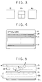
- Figs. 1A and 1B are magnified views of the surface of a conventional optical recording medium, wherein 13 indicates a tracking track formed in advance on said surface, for example as a stripe-shaped area of different reflectance.
- Three beam spots 15, 16, 17 perform a scanning motion in a direction B, in such a manner that the beam spot 16 runs along the center of the tracking track 13, while each of the beam spots 15, 17 half rides the track 13.
- a tracking signal is obtained from the difference of the detection signals obtained by detecting the lights of the spots 15, 17 and is utilized for controlling the beam spots 15, 16, 17, in order to record information in the tracking track 13 with the beam spot 16 as shown in Fig. 1A or reproduce information recorded in the track 13 as shown in Fig. 1B.
- the record pits 35 are formed to the end of the tracking tracks 34a, 34b, 34c in the longitudinal direction of the optical card 31, a first side spot S1 no longer has the tracking track to follow when the main spot S2 reaches the end record pit. Consequently the intensities of the reflected beams from the side spots S1 and S3 become unbalanced, and stable auto tracking cannot be expected.
- an optical recording medium in accordance with claim 1.
- Fig. 2 is a schematic view of an optical information record/reproduction apparatus.
- a light beam emitted from a light source 1 such as a semiconductor laser is rendered parallel by a collimating lens 2, and is split into three beams by a diffraction grating 3.
- the divided light beams are reflected by a beam splitter 4 and is focused by an objective lens 5 onto an optical card 6 to form three beam spots S1, S2, S3.
- the light beams reflected by the optical card 6 again pass through the objective lens 5 and are separated from the incident beams by the beam splitter 4.
- Said reflected beams are then reflected by a mirror 7, then condensed by a sensor lens 8 and a cylindrical lens 9 and enter photosensors 10-1, 10-2, 10-3 which are so positioned as to respectively receive the lights from the beam spots S1, S2, S3.
- the light-receiving face of said photosensor 10-2 is divided into four areas, and the difference between the sums of the detection signals of two sets of diagonally positioned light-receiving areas can be utilized for determining the astigmatic aberration introduced by said cylindrical lens 9.
- a focusing signal is obtained by the already known astigmatism method.
- a reproduction signal is obtained from said photosensor 10-2.
- the difference of the signals from the photosensors 10-1 and 10-3 is obtained by a differential amplifier 11 and is released as a tracking signal S T from a terminal 12.
- Said tracking signal S T is fed, by an unrepresented circuit, back to a lens actuator 18 to displace the objective lens 5 in a direction perpendicular to the optical axis thereof, thus achieving auto tracking.
- the optical card 6 is reciprocated in a direction R by an unrepresented driving mechanism, whereby the spots S1, S2, S3 scan the optical card 6.
- An optical head 19, containing the aforementioned optical system is rendered movable, for access to tracks, in a direction perpendicular to the direction R, or a direction perpendicular to the plane of Fig. 2.
- Fig. 4 is a plan view of the above-mentioned optical card, consisting of a substrate for example of a plastic material, and a recording layer 20 formed thereon and composed of a silver halide material, a dye or a chalcogenide material.
- Said recording layer 20 is provided with mutually parallel plural tracking tracks 21 which are optically detectable for example by their relief or by their difference in reflectance. These tracking tracks 21 are formed at a constant pitch, and recording areas for information recording are formed between said tracking tracks 21.
- Fig. 5 is a magnified plan view of the recording surface of said optical card 6, for explaining the recording process utilizing the apparatus shown in Fig. 2.
- Recording areas 22-1, 22-2 are formed between the tracking tracks 21-1, 21-2, 21-3.
- the beam spots S1, S3 are so projected that they partly ride respectively the tracking tracks 21-1, 21-2, and the beam spot S2 is projected on the recording area 22-1. If the beam spots S1-S3 are displaced perpendicularly to the tracks, the intensity of the beam reflected from the spot S1 becomes different from that of the beam reflected from the spot S3. Consequently, as shown in Fig. 2, the difference of the signals obtained by detecting said reflected beams provides a stacking signal ST indicating the quantity and direction of said displacement.
- An auto tracking based on said tracking signal exactly guides the beam spot S2 always on the recording area between two tracking tracks, and allows information recording as shown by record pits 23.
- the beam spots S1, S2, S3 are so projected that they are respectively present on the tracking track 21-2, recording area 22-2 and tracking track 21-3.
- the beam spot S1 or S3 usually has a Gaussian intensity distribution on the optical card, stronger at the center of the spot. Thus, if each of such spots is so positioned as to half ride the tracking track, a large change in the light intensity is obtained even by a small displacement, thus ensuring a highly sensitive tracking signal detection.
- D1, D2 or D3 indicates the diameter of a portion where the light intensity is 1/e of the peak intensity.
- the optical recording medium preferably satisfies the relation: L ⁇ 2W i.e. the width L of the recording area between the tracking tracks is equal to or larger than twice of the width W of the tracking track.
- Fig. 5 only shows the case of information recording, but the detection of the tracking signal can be conducted in the identical manner in case of reproducing the information already recorded in the recording area.
- Fig. 6 shows a case of reading record pits 23 with the beam spot S2.
- the beam spots S1, S3 are so projected that they partly ride respectively the tracking tracks 21-1 and 21-2, and the tracking signal is obtained by comparing the intensity of the light beams reflected from said spots.
- the beam spots are positioned on the edges of the tracking tracks closer to the area for information recording or reproduction, but they may instead be positioned on the edges farther from said area as shown in Fig. 7, in order to detect the tracking signal.
- the same components as those in Fig. 5 are represented by same reference numerals and will not be explained further.
- the tracking signal detecting method described has the advantage that it is insensitive to the inclination of the surface of the optical recording medium, as will be explained in the following.
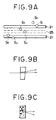
- Fig. 8A shows a part of the optical system shown in Fig. 2, wherein the same components as those in Fig. 2 are represented by same reference numerals. If the surface 6-1 of the optical recording medium is perpendicular to the optical axis, the principal ray of the light beam proceeds along the optical axis and reaches the sensor 10 as represented by solid lines. However, if said surface is inclined by ⁇ as represented by 6-2, the principal ray of the reflected beam is displaced from the optical axis when reaching the sensor 10.
- the light-receiving face of said sensor 10 is not in a conjugate position F to the surface of the optical recording medium with respect to the lens system consisting of the objective lens 5, sensor lens 8 and cylindrical lens 9, the light beam is displaced by ⁇ d on the surface of the sensor.
- the photosensors can be positioned conjugate with the surface of the optical recording medium. Also, even if they are not in the conjugate position, the photosensors 10-1 and 10-3 may be formed large enough, as shown in Fig. 8B, as to absorb the influence of the displacement ⁇ d. Therefore the aforementioned offset no longer appears, and exact tracking signal can be detected even when the surface of the recording medium is inclined.
- This method being little influenced by the inclination of the surface of the recording medium, is particularly suitable for an optical card which will often be bent when being carried.
- the auto focusing signal is detected by the astigmatic property of the beam spot S2.
- the presence of record pits may affect the auto focusing signal as shown in Fig. 1.
- a beam angle separating element utilizing a rear reflection of a wedge prism or a double refraction of a crystal such as Wolaston prism, as respectively shown in Figs. 9B and 9C, is placed between the diffraction grating 3 and the beam splitter 4 shown in Fig. 2, to form additional beam spots S4 - S6, simultaneously with the beam spots S1 - S3.
- the beam spot S5 is positioned in a non-recorded area between the tracking track 21 and the signal track 25 on which the record pits are formed, and is utilized for detecting the focusing signal. In this manner there is achieved stable auto focusing without the influence of the record pits.
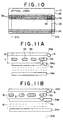
- Fig. 10 is a schematic plan view of a card embodying the present invention.
- An optical card 31 is composed of a flexible rectangular substrate 32 such as a plastic sheet, and a recording layer 33 formed thereon and composed for example of a silver halide material, a dye or a chalcogenide material.
- Said recording layer 33 is limited to areas 37a and 37b, so that information recording is not possible on both ends in the longitudinal direction of the optical card 31.
- Such tracking tracks 34 can be made for example by forming plural grooves on the substrate.
- the substrate 32 is provided only with plural tracking tracks 34.
- plural tracking tracks 34 and plural recording areas 36 for forming record pits are provided in the area between 37a and 37b.
- the relation between the width W of said tracking tracks and the gap L between said tracks is same as in the optical card shown in Fig. 4.
- the record pits 35 are formed to the end of the tracking tracks 34a, 34b, 34c in the longitudinal direction of the optical card 31, a first side spot S1 no longer has the tracking track to follow when the main spot S2 reaches the end record pit. Consequently the intensities of the reflected beams from the side spots S1 and S3 become unbalanced, and stable auto tracking cannot be expected.
- an area without record pits of a length at least of the diameter of the side spot S1 or S3 (no longer diameter if said spots are not circular) inwardly from the end of the tracking tracks 34a, 34b, 34c (to the right from 37b in Fig. 11B), so that the first side spot S1 still has the tracking track to follow when the main spot S2 is positioned at the record pit at the right end. Consequently the intensities of the reflected beams from the first and second side spots S1, S3 are mutually balanced to achieve stable auto tracking.
- the layer may extend to the ends of the recording tracks but in this case the recording area may stop short and can be defined by an optically detectable mark provided in the recording layer.
Landscapes
- Optical Recording Or Reproduction (AREA)
Description
- The present invention relates to an optically readable recording medium. An embodiment of the invention allows information recording by irradiation with a light beam and optical reproduction of thus recorded information.
- The invention also relates to a method for detecting tracking signals from said medium. The tracking signal detecting method of the present invention is applicable to an apparatus designed solely for information recording, an apparatus designed solely for information reproduction, and an apparatus designed for both information recording and reproduction.
- Recently developed or commercialized are electronic file systems utilizing compact disks or add-on type optical disks, and optical disk systems utilizing erasable magnetooptical or phase transition material. Also recently attracting attention is optical card system in which information recording and reproduction are conducted on a card-shaped optical recording medium. Such optical card is characterized by its portability because of its shape, and by a large information capacity per area, as a disk-shaped recording medium is unable to record information in the central portion.
- The above-mentioned optical recording media record information in the form of an information track or a train of optically detectable recording pits, by scanning of the surface of said media with a light beam focused to a small spot and modulated according to the information to be recorded. Thus, in order to correctly record information without trouble such as crossing of information tracks, it is necessary to control the irradiating position of said light beam in a direction perpendicular to the scanning direction, and such control function is called auto-tracking. In the following there will be explained one known arrangement of guide tracks with respect to Figure 1.
- Figs. 1A and 1B are magnified views of the surface of a conventional optical recording medium, wherein 13 indicates a tracking track formed in advance on said surface, for example as a stripe-shaped area of different reflectance. Three
beam spots beam spot 16 runs along the center of thetracking track 13, while each of thebeam spots track 13. A tracking signal is obtained from the difference of the detection signals obtained by detecting the lights of thespots beam spots tracking track 13 with thebeam spot 16 as shown in Fig. 1A or reproduce information recorded in thetrack 13 as shown in Fig. 1B. - In such a known method, however, stable auto tracking is often not possible, since
record pits 14, indicated by hatched areas, are present in the running trajectory of thebeam spots record pits 14 may be mixed in the tracking signal. Particularly in case of information recording as shown in Fig. 1A, therecord pits 14 are present always at the side of thebeam spot 15, so that the lights from thebeam spots - Another known arrangement of guide tracks is disclosed in EP0164131 in which two guide tracks are provided on either side of each recording track and the equivalent of the three
beam spots beams middle beam spot 16 rides the recording track which is located between the two guide tracks. - However, there is a problem associated with this other known arrangement and this problem will now be described with reference to Figure 11A.
- As shown in Fig. 11A, the
record pits 35 are formed to the end of thetracking tracks optical card 31, a first side spot S1 no longer has the tracking track to follow when the main spot S2 reaches the end record pit. Consequently the intensities of the reflected beams from the side spots S1 and S3 become unbalanced, and stable auto tracking cannot be expected. - According to a first aspect of the present invention there is provided an optical recording medium in accordance with claim 1.
- According to a second aspect of the present invention, there is provided a method for information recording or reproducing in accordance with
claim 5. - How the invention may be carried out will now be described, by way of example only, and with reference to the accompanying drawings to which:
-
- Figs. 1A and 1B are schematic views showing a known arrangement of guide tracks on an optical recording medium;
- Fig. 2 is a schematic view of an optical information record/reproduction apparatus embodying a tracking signal detecting method for use with an optical card;
- Fig. 3 is a plan view of the light-receiving face of a photosensor shown in Fig. 2;
- Fig. 4 is a plan view of an optical card embodying another arrangement of guide tracks;
- Figs. 5, 6 and 7 are magnified view of the recording surface of the optical card of Figure 4 showing the tracking signal detecting method;
- Figs. 8A, 8B and 8C are schematic views showing the influence of the inclination of the surface of the medium to the tracking signal;
- Figs. 9A, 9B and 9C are shematic views showing a further auto tracking arrangement;
- Fig. 10 is a schematic view showing an optical card embodying the present invention;
- Fig. 11A is a view similar to Figure 5 showing the beam spots when at the end of a recording area; and
- Fig. 11B is a view similar to Figure 11A but relating to the embodiment of the present invention shown in Figure 10 on an enlarged scale.
- Although the embodiment of the invention is shown in Figures 10 and 11B the arrangement shown in Figures 2 to 9 will first be described in order to enable the present invention to be better appreciated.
- Fig. 2 is a schematic view of an optical information record/reproduction apparatus. A light beam emitted from a light source 1 such as a semiconductor laser is rendered parallel by a
collimating lens 2, and is split into three beams by a diffraction grating 3. The divided light beams are reflected by abeam splitter 4 and is focused by anobjective lens 5 onto anoptical card 6 to form three beam spots S1, S2, S3. The light beams reflected by theoptical card 6 again pass through theobjective lens 5 and are separated from the incident beams by thebeam splitter 4. Said reflected beams are then reflected by amirror 7, then condensed by asensor lens 8 and acylindrical lens 9 and enter photosensors 10-1, 10-2, 10-3 which are so positioned as to respectively receive the lights from the beam spots S1, S2, S3. - As shown in Fig. 3, the light-receiving face of said photosensor 10-2 is divided into four areas, and the difference between the sums of the detection signals of two sets of diagonally positioned light-receiving areas can be utilized for determining the astigmatic aberration introduced by said
cylindrical lens 9. Thus a focusing signal is obtained by the already known astigmatism method. Also in the reproduction of information, a reproduction signal is obtained from said photosensor 10-2. Also the difference of the signals from the photosensors 10-1 and 10-3 is obtained by a differential amplifier 11 and is released as a tracking signal ST from aterminal 12. Said tracking signal ST is fed, by an unrepresented circuit, back to alens actuator 18 to displace theobjective lens 5 in a direction perpendicular to the optical axis thereof, thus achieving auto tracking. - The
optical card 6 is reciprocated in a direction R by an unrepresented driving mechanism, whereby the spots S1, S2, S3 scan theoptical card 6. Anoptical head 19, containing the aforementioned optical system is rendered movable, for access to tracks, in a direction perpendicular to the direction R, or a direction perpendicular to the plane of Fig. 2. - Fig. 4 is a plan view of the above-mentioned optical card, consisting of a substrate for example of a plastic material, and a
recording layer 20 formed thereon and composed of a silver halide material, a dye or a chalcogenide material. Said recordinglayer 20 is provided with mutually parallelplural tracking tracks 21 which are optically detectable for example by their relief or by their difference in reflectance. Thesetracking tracks 21 are formed at a constant pitch, and recording areas for information recording are formed between saidtracking tracks 21. - Fig. 5 is a magnified plan view of the recording surface of said
optical card 6, for explaining the recording process utilizing the apparatus shown in Fig. 2. Recording areas 22-1, 22-2 are formed between the tracking tracks 21-1, 21-2, 21-3. The beam spots S1, S3 are so projected that they partly ride respectively the tracking tracks 21-1, 21-2, and the beam spot S2 is projected on the recording area 22-1. If the beam spots S1-S3 are displaced perpendicularly to the tracks, the intensity of the beam reflected from the spot S1 becomes different from that of the beam reflected from the spot S3. Consequently, as shown in Fig. 2, the difference of the signals obtained by detecting said reflected beams provides a stacking signal ST indicating the quantity and direction of said displacement. An auto tracking based on said tracking signal exactly guides the beam spot S2 always on the recording area between two tracking tracks, and allows information recording as shown by record pits 23. Also in case of recording information on the recording area 22-2, the beam spots S1, S2, S3 are so projected that they are respectively present on the tracking track 21-2, recording area 22-2 and tracking track 21-3. The beam spot S1 or S3 usually has a Gaussian intensity distribution on the optical card, stronger at the center of the spot. Thus, if each of such spots is so positioned as to half ride the tracking track, a large change in the light intensity is obtained even by a small displacement, thus ensuring a highly sensitive tracking signal detection. - Referring to Fig. 5, the width W of the tracking tracks 21-1 - 21-3 preferably satisfies the relation:


- Thus, based on the relations (1) and (2), the optical recording medium preferably satisfies the relation:

- Fig. 5 only shows the case of information recording, but the detection of the tracking signal can be conducted in the identical manner in case of reproducing the information already recorded in the recording area. Fig. 6 shows a case of reading
record pits 23 with the beam spot S2. For this purpose the beam spots S1, S3 are so projected that they partly ride respectively the tracking tracks 21-1 and 21-2, and the tracking signal is obtained by comparing the intensity of the light beams reflected from said spots. In Fig. 5, the beam spots are positioned on the edges of the tracking tracks closer to the area for information recording or reproduction, but they may instead be positioned on the edges farther from said area as shown in Fig. 7, in order to detect the tracking signal. In Fig. 7, the same components as those in Fig. 5 are represented by same reference numerals and will not be explained further. - The tracking signal detecting method described has the advantage that it is insensitive to the inclination of the surface of the optical recording medium, as will be explained in the following.
- Fig. 8A shows a part of the optical system shown in Fig. 2, wherein the same components as those in Fig. 2 are represented by same reference numerals. If the surface 6-1 of the optical recording medium is perpendicular to the optical axis, the principal ray of the light beam proceeds along the optical axis and reaches the
sensor 10 as represented by solid lines. However, if said surface is inclined by θ as represented by 6-2, the principal ray of the reflected beam is displaced from the optical axis when reaching thesensor 10. Thus, if the light-receiving face of saidsensor 10 is not in a conjugate position F to the surface of the optical recording medium with respect to the lens system consisting of theobjective lens 5,sensor lens 8 andcylindrical lens 9, the light beam is displaced by Δd on the surface of the sensor. - Thus, in the so-called push-pull method in which a photosensor with split light-receiving faces 24-1, 24-2 as shown in Fig. 8C is positioned on the pupil plane of the lenses and the tracking signal is detected from the difference of the detection signals of said split light receiving faces, the above-mentioned displacement Ad of the light beam is directly detected as an asymmetric distribution of the light beam, thereby generating an offset in the tracking signal and rendering exact auto tracking impossible.
- On the other hand, the photosensors can be positioned conjugate with the surface of the optical recording medium. Also, even if they are not in the conjugate position, the photosensors 10-1 and 10-3 may be formed large enough, as shown in Fig. 8B, as to absorb the influence of the displacement Δd. Therefore the aforementioned offset no longer appears, and exact tracking signal can be detected even when the surface of the recording medium is inclined.
- This method being little influenced by the inclination of the surface of the recording medium, is particularly suitable for an optical card which will often be bent when being carried.
- The auto focusing signal is detected by the astigmatic property of the beam spot S2. However, also in the beam spot S2, the presence of record pits may affect the auto focusing signal as shown in Fig. 1. In such case, a beam angle separating element utilizing a rear reflection of a wedge prism or a double refraction of a crystal such as Wolaston prism, as respectively shown in Figs. 9B and 9C, is placed between the
diffraction grating 3 and thebeam splitter 4 shown in Fig. 2, to form additional beam spots S4 - S6, simultaneously with the beam spots S1 - S3. The beam spot S5 is positioned in a non-recorded area between the trackingtrack 21 and thesignal track 25 on which the record pits are formed, and is utilized for detecting the focusing signal. In this manner there is achieved stable auto focusing without the influence of the record pits. In this embodiment, as will be apparent from Fig. 9A, the width L of the recording area between the tracking tracks is about triple of the track width W, or L = 3W. - Fig. 10 is a schematic plan view of a card embodying the present invention. An
optical card 31 is composed of a flexiblerectangular substrate 32 such as a plastic sheet, and arecording layer 33 formed thereon and composed for example of a silver halide material, a dye or a chalcogenide material. Saidrecording layer 33 is limited to areas 37a and 37b, so that information recording is not possible on both ends in the longitudinal direction of theoptical card 31. - Over the entire longitudinal dimension of the
optical card 31 there are provided plural stripe-shaped linear tracking tracks 34 in parallel manner. Such tracking tracks can be made for example by forming plural grooves on the substrate. - Consequently, in the end portions outside 37a and 37b in the longitudinal direction of the
optical card 31, thesubstrate 32 is provided only with plural tracking tracks 34. In the area between 37a and 37b, there are provided plural tracking tracks 34 andplural recording areas 36 for forming record pits, each positioned between two neighboring tracking tracks. The relation between the width W of said tracking tracks and the gap L between said tracks is same as in the optical card shown in Fig. 4. - The information recording and reproduction are conducted in the same manner as already explained in relation to Figs. 5 and 6.
- This shows the arrangement of Fig. 10 on an enlarged scale.
- As shown in Fig. 11A, the record pits 35 are formed to the end of the tracking tracks 34a, 34b, 34c in the longitudinal direction of the
optical card 31, a first side spot S1 no longer has the tracking track to follow when the main spot S2 reaches the end record pit. Consequently the intensities of the reflected beams from the side spots S1 and S3 become unbalanced, and stable auto tracking cannot be expected. - There is provided an area without record pits, of a length at least of the diameter of the side spot S1 or S3 (no longer diameter if said spots are not circular) inwardly from the end of the tracking tracks 34a, 34b, 34c (to the right from 37b in Fig. 11B), so that the first side spot S1 still has the tracking track to follow when the main spot S2 is positioned at the record pit at the right end. Consequently the intensities of the reflected beams from the first and second side spots S1, S3 are mutually balanced to achieve stable auto tracking.
- Instead of the recording layer stopping short of the end of the guide tracks as in Figure 11B, the layer may extend to the ends of the recording tracks but in this case the recording area may stop short and can be defined by an optically detectable mark provided in the recording layer.
Claims (6)
- A cardlike optical recording medium adapted to be recorded on and reproduced from with a 3-beam optical system, the medium comprising a substrate (6,32) with at least a recording surface carrying a recording layer (20,33), linear continuous tracking tracks (21,34) formed on the recording surface (20,33) parallel to one another with a constant distance therebetween which is equal to or larger than twice the width of said tracking tracks, and recording areas (22,36) being formed between the tracking tracks, wherein the tracking tracks extend at their ends beyond the ends of the recording areas such that an auxiliary beam of the 3-beam optical system which precedes the main beam and follows one of said tracking tracks (21,34) is still impinging on the tracking track when the main beam reaches the end of the recording area.
- An optical recording medium according to claim 1, wherein a recording layer is provided solely on only part of the recording surface and that the length of the recording area (22,36) is limited by the length of the recording layer in its longitudinal direction.
- An optical recording medium according to claim 2, wherein said recording layer is composed of a material selected from a group consisting of silver halide, dye and chalcogenide.
- An optical recording medium according to claim 1, wherein said substrate comprises a plastic sheet.
- A method for information recording or reproducing to or from a card-like optical recording medium (6,32) comprising a plurality of linear continuous tracking tracks (21,34) extending parallel to one another, and further comprising a plurality of recording areas (22,36) formed between neighbouring of said tracking tracks (21,34), said method comprising the steps of:scanning each of the plurality of recording areas (22,36) with a main beam (52) and each of the two neighbouring tracks (21,34) with one of two auxilliary beams (51,53); of which auxilliary beams (51,53) at least one precedes the main beam (52);obtaining a tracking signal from the auxilliary beams (51,53);recording or reproducing the information with the main beam (52) wherein the length of each of the tracking tracks (21,34) on the medium in a longitudinal direction is longer than the length of the recording area (22,36), so that when the main beam is applied to the extreme end of the recording area in the longitudinal direction, the preceding auxiliary beam is applied to such portion of the tracking track beyond the recording area in the longitudinal direction.
- A method according to claim 5, wherein the two auxilliary beams (51,53) respectively preceding and succeeding the main beam (52), respectively scan the tracking tracks (21,34) both adjacent to the recording area (22,36) scanned by the main beam.
Applications Claiming Priority (6)
| Application Number | Priority Date | Filing Date | Title |
|---|---|---|---|
| JP82928/86 | 1986-04-09 | ||
| JP82929/86 | 1986-04-09 | ||
| JP8292886A JPS62239333A (en) | 1986-04-09 | 1986-04-09 | Tracking signal detection method |
| JP61082929A JPS62239343A (en) | 1986-04-09 | 1986-04-09 | Optical recording medium |
| JP187854/86 | 1986-08-12 | ||
| JP61187854A JPS6344322A (en) | 1986-08-12 | 1986-08-12 | Optical information recording medium |
Publications (3)
| Publication Number | Publication Date |
|---|---|
| EP0241267A1 EP0241267A1 (en) | 1987-10-14 |
| EP0241267B1 EP0241267B1 (en) | 1992-04-01 |
| EP0241267B2 true EP0241267B2 (en) | 1996-03-13 |
Family
ID=27304050
Family Applications (1)
| Application Number | Title | Priority Date | Filing Date |
|---|---|---|---|
| EP87303015A Expired - Lifetime EP0241267B2 (en) | 1986-04-09 | 1987-04-07 | Optical recording medium |
Country Status (4)
| Country | Link |
|---|---|
| US (1) | US5070490A (en) |
| EP (1) | EP0241267B2 (en) |
| CA (1) | CA1295734C (en) |
| DE (1) | DE3777863D1 (en) |
Families Citing this family (7)
| Publication number | Priority date | Publication date | Assignee | Title |
|---|---|---|---|---|
| DE68923833T2 (en) * | 1988-06-20 | 1996-06-13 | Mitsubishi Electric Corp | Optical head with tilt correction servomechanism. |
| JPH04274058A (en) * | 1991-02-28 | 1992-09-30 | Olympus Optical Co Ltd | Information recording and reproducing device |
| JPH05101431A (en) * | 1991-10-07 | 1993-04-23 | Sony Corp | Optical disc playback device |
| US6199761B1 (en) | 1996-12-09 | 2001-03-13 | Drexler Technology Corporation | Validation method for electronic cash cards and digital identity cards utilizing optical data storage |
| US5932865A (en) * | 1996-12-09 | 1999-08-03 | Drexler Technology Corporation | Anti-counterfeit validation method for electronic cash cards employing an optical memory stripe |
| US20040182933A1 (en) * | 2003-03-17 | 2004-09-23 | Kai-Yuan Tien | Light source structure without moving parts for a laser barcode scanner |
| KR20160052702A (en) * | 2013-10-29 | 2016-05-12 | 소니 코포레이션 오브 아메리카 | Array reader and array reading of optical media |
Family Cites Families (18)
| Publication number | Priority date | Publication date | Assignee | Title |
|---|---|---|---|---|
| JPS5753831A (en) * | 1980-09-12 | 1982-03-31 | Olympus Optical Co Ltd | Method and device for reproduction of optical information |
| JPS58500437A (en) * | 1981-02-27 | 1983-03-24 | ドレクスラ−・テクノロジイ・コ−ポレ−ション | Banking cards for automated teller machines, etc. |
| JPS5888838A (en) * | 1981-11-19 | 1983-05-27 | Sony Corp | Optical signal recording system |
| US4642803A (en) * | 1982-08-09 | 1987-02-10 | Drexler Technology Corporation | Optical data retrieval system for multi-characteristic reflective data storage media |
| JPS59207039A (en) * | 1983-05-07 | 1984-11-24 | Kyodo Printing Co Ltd | Optical recording card |
| US4703408A (en) * | 1983-11-28 | 1987-10-27 | Hitachi, Ltd. | Apparatus and record carrier for optically writing information |
| JPS60197953A (en) * | 1984-03-21 | 1985-10-07 | Hitachi Ltd | Information recording device |
| US4598393A (en) * | 1984-04-06 | 1986-07-01 | Drexler Technology Corporation | Three-beam optical servo tracking system with two-track parallel readout |
| EP0164061B1 (en) * | 1984-06-01 | 1989-05-17 | Matsushita Electric Industrial Co., Ltd. | Optical disk exclusively used for reproduction |
| JPS60261043A (en) * | 1984-06-07 | 1985-12-24 | Victor Co Of Japan Ltd | Information recording medium disc |
| EP0166614A3 (en) * | 1984-06-29 | 1987-12-23 | Minnesota Mining And Manufacturing Company | Encoated optical recording medium |
| US4787075A (en) * | 1984-12-26 | 1988-11-22 | Canon Kabushiki Kaisha | Optical information recording medium and apparatus for recording/reproducing information using the same |
| JPS61151792A (en) * | 1984-12-26 | 1986-07-10 | Canon Inc | Optical information recording media |
| US4652730A (en) * | 1985-01-03 | 1987-03-24 | Honeywell Information Systems Inc. | Method and apparatus for skew compensation in an optical reader |
| JPS61192075A (en) * | 1985-02-20 | 1986-08-26 | Canon Inc | Information recording carrier and its reproduction method |
| EP0242118B1 (en) * | 1986-04-09 | 1992-01-22 | Canon Kabushiki Kaisha | An optical information medium and apparatus for reading information from, and/or writing information on, such a medium |
| US4910725A (en) * | 1986-04-23 | 1990-03-20 | Drexler Technology Corporation | Optical recording method for data cards |
| US4730293A (en) * | 1986-09-15 | 1988-03-08 | Drexler Technology Corporation | Dual beam optical data system |
-
1987
- 1987-04-03 CA CA000533847A patent/CA1295734C/en not_active Expired - Lifetime
- 1987-04-07 DE DE8787303015T patent/DE3777863D1/en not_active Expired - Lifetime
- 1987-04-07 EP EP87303015A patent/EP0241267B2/en not_active Expired - Lifetime
-
1990
- 1990-02-13 US US07/479,205 patent/US5070490A/en not_active Expired - Lifetime
Also Published As
| Publication number | Publication date |
|---|---|
| EP0241267A1 (en) | 1987-10-14 |
| DE3777863D1 (en) | 1992-05-07 |
| CA1295734C (en) | 1992-02-11 |
| EP0241267B1 (en) | 1992-04-01 |
| US5070490A (en) | 1991-12-03 |
Similar Documents
| Publication | Publication Date | Title |
|---|---|---|
| CA1251561A (en) | Optical information recording medium and apparatus for recording/reproducing information using the same | |
| EP0026517B1 (en) | Record carrier containing information in an optically readable information structure, as well as apparatus for reading said carrier | |
| US4587648A (en) | Optical disk | |
| EP0354019B1 (en) | Optical head device for reading information stored in a recording medium | |
| EP0073066B1 (en) | Optical recording apparatus | |
| EP0777221B1 (en) | Reproducing and recording optical pickup compatible for discs having different thicknesses | |
| US4498159A (en) | Track deviation detecting apparatus | |
| EP0439196A2 (en) | Optical disk | |
| US6549509B2 (en) | Three-dimensional optical memory | |
| EP0241267B2 (en) | Optical recording medium | |
| EP0646909B1 (en) | Optical information recording/reproduction method and apparatus | |
| EP0814465A2 (en) | Optical pickup apparatus for reproduction of information record medium | |
| EP0654784B1 (en) | Optical head for generating a plurality of light beams and an opto-magnetic recording/reproducing/erasing apparatus using same | |
| US5684781A (en) | Optical pickup for recording/reproducing double-sided disc | |
| EP0173533A2 (en) | An optical memory device | |
| EP0737964A1 (en) | An apparatus for and method of reproducing information from different types of optical disks and an optical disk recording/reproducing apparatus | |
| EP0829863A2 (en) | Optical pickup | |
| US4879691A (en) | Optical recording system with optical recording medium having multilevel recording surface for tracking | |
| US6373808B1 (en) | Optical pick-up apparatus capable of eliminating a cross-talk component from adjacent tracks | |
| CA1303738C (en) | Optical information recording and reproducing apparatus | |
| JPH0457224A (en) | Optical head device | |
| JP2765191B2 (en) | Optical head device | |
| JPS62239333A (en) | Tracking signal detection method | |
| JP2501270B2 (en) | Optical information recording method | |
| JPS639038A (en) | Optical system for optical information |
Legal Events
| Date | Code | Title | Description |
|---|---|---|---|
| PUAI | Public reference made under article 153(3) epc to a published international application that has entered the european phase |
Free format text: ORIGINAL CODE: 0009012 |
|
| AK | Designated contracting states |
Kind code of ref document: A1 Designated state(s): DE FR GB IT NL |
|
| 17P | Request for examination filed |
Effective date: 19880302 |
|
| 17Q | First examination report despatched |
Effective date: 19891117 |
|
| GRAA | (expected) grant |
Free format text: ORIGINAL CODE: 0009210 |
|
| AK | Designated contracting states |
Kind code of ref document: B1 Designated state(s): DE FR GB IT NL |
|
| ET | Fr: translation filed | ||
| REF | Corresponds to: |
Ref document number: 3777863 Country of ref document: DE Date of ref document: 19920507 |
|
| ITF | It: translation for a ep patent filed | ||
| PLBI | Opposition filed |
Free format text: ORIGINAL CODE: 0009260 |
|
| 26 | Opposition filed |
Opponent name: BERGER RUDOLF Effective date: 19921231 |
|
| NLR1 | Nl: opposition has been filed with the epo |
Opponent name: BERGER, RUDOLF |
|
| ITTA | It: last paid annual fee | ||
| PUAH | Patent maintained in amended form |
Free format text: ORIGINAL CODE: 0009272 |
|
| STAA | Information on the status of an ep patent application or granted ep patent |
Free format text: STATUS: PATENT MAINTAINED AS AMENDED |
|
| 27A | Patent maintained in amended form |
Effective date: 19960313 |
|
| AK | Designated contracting states |
Kind code of ref document: B2 Designated state(s): DE FR GB IT NL |
|
| NLR2 | Nl: decision of opposition | ||
| ET3 | Fr: translation filed ** decision concerning opposition | ||
| NLR3 | Nl: receipt of modified translations in the netherlands language after an opposition procedure | ||
| ITF | It: translation for a ep patent filed | ||
| APAC | Appeal dossier modified |
Free format text: ORIGINAL CODE: EPIDOS NOAPO |
|
| APAC | Appeal dossier modified |
Free format text: ORIGINAL CODE: EPIDOS NOAPO |
|
| REG | Reference to a national code |
Ref country code: GB Ref legal event code: IF02 |
|
| APAH | Appeal reference modified |
Free format text: ORIGINAL CODE: EPIDOSCREFNO |
|
| PGFP | Annual fee paid to national office [announced via postgrant information from national office to epo] |
Ref country code: GB Payment date: 20060418 Year of fee payment: 20 |
|
| PGFP | Annual fee paid to national office [announced via postgrant information from national office to epo] |
Ref country code: NL Payment date: 20060419 Year of fee payment: 20 |
|
| PGFP | Annual fee paid to national office [announced via postgrant information from national office to epo] |
Ref country code: FR Payment date: 20060426 Year of fee payment: 20 |
|
| PGFP | Annual fee paid to national office [announced via postgrant information from national office to epo] |
Ref country code: IT Payment date: 20060430 Year of fee payment: 20 |
|
| PGFP | Annual fee paid to national office [announced via postgrant information from national office to epo] |
Ref country code: DE Payment date: 20060621 Year of fee payment: 20 |
|
| PG25 | Lapsed in a contracting state [announced via postgrant information from national office to epo] |
Ref country code: NL Free format text: LAPSE BECAUSE OF EXPIRATION OF PROTECTION Effective date: 20070407 |
|
| REG | Reference to a national code |
Ref country code: GB Ref legal event code: PE20 |
|
| NLV7 | Nl: ceased due to reaching the maximum lifetime of a patent |
Effective date: 20070407 |
|
| PG25 | Lapsed in a contracting state [announced via postgrant information from national office to epo] |
Ref country code: GB Free format text: LAPSE BECAUSE OF EXPIRATION OF PROTECTION Effective date: 20070406 |