EP0241007A2 - Optical head - Google Patents
Optical head Download PDFInfo
- Publication number
- EP0241007A2 EP0241007A2 EP87105191A EP87105191A EP0241007A2 EP 0241007 A2 EP0241007 A2 EP 0241007A2 EP 87105191 A EP87105191 A EP 87105191A EP 87105191 A EP87105191 A EP 87105191A EP 0241007 A2 EP0241007 A2 EP 0241007A2
- Authority
- EP
- European Patent Office
- Prior art keywords
- substrate
- plane
- optical head
- light
- bundle
- Prior art date
- Legal status (The legal status is an assumption and is not a legal conclusion. Google has not performed a legal analysis and makes no representation as to the accuracy of the status listed.)
- Granted
Links
- 230000003287 optical effect Effects 0.000 title claims abstract description 21
- 230000006872 improvement Effects 0.000 claims description 2
- 239000000758 substrate Substances 0.000 description 35
- 239000004033 plastic Substances 0.000 description 11
- 229920003023 plastic Polymers 0.000 description 11
- 239000004417 polycarbonate Substances 0.000 description 5
- 229920000515 polycarbonate Polymers 0.000 description 5
- 239000011521 glass Substances 0.000 description 4
- 230000010287 polarization Effects 0.000 description 3
- 230000006866 deterioration Effects 0.000 description 2
- 238000001746 injection moulding Methods 0.000 description 2
- 230000004048 modification Effects 0.000 description 2
- 238000012986 modification Methods 0.000 description 2
- 229920002972 Acrylic fiber Polymers 0.000 description 1
- 230000000694 effects Effects 0.000 description 1
- 230000008030 elimination Effects 0.000 description 1
- 238000003379 elimination reaction Methods 0.000 description 1
- 230000002349 favourable effect Effects 0.000 description 1
- 239000000463 material Substances 0.000 description 1
- 239000002184 metal Substances 0.000 description 1
- 229910052751 metal Inorganic materials 0.000 description 1
- 150000002739 metals Chemical class 0.000 description 1
- 239000000123 paper Substances 0.000 description 1
- 238000002834 transmittance Methods 0.000 description 1
Images


Classifications
-
- G—PHYSICS
- G11—INFORMATION STORAGE
- G11B—INFORMATION STORAGE BASED ON RELATIVE MOVEMENT BETWEEN RECORD CARRIER AND TRANSDUCER
- G11B11/00—Recording on or reproducing from the same record carrier wherein for these two operations the methods are covered by different main groups of groups G11B3/00 - G11B7/00 or by different subgroups of group G11B9/00; Record carriers therefor
- G11B11/10—Recording on or reproducing from the same record carrier wherein for these two operations the methods are covered by different main groups of groups G11B3/00 - G11B7/00 or by different subgroups of group G11B9/00; Record carriers therefor using recording by magnetic means or other means for magnetisation or demagnetisation of a record carrier, e.g. light induced spin magnetisation; Demagnetisation by thermal or stress means in the presence or not of an orienting magnetic field
- G11B11/105—Recording on or reproducing from the same record carrier wherein for these two operations the methods are covered by different main groups of groups G11B3/00 - G11B7/00 or by different subgroups of group G11B9/00; Record carriers therefor using recording by magnetic means or other means for magnetisation or demagnetisation of a record carrier, e.g. light induced spin magnetisation; Demagnetisation by thermal or stress means in the presence or not of an orienting magnetic field using a beam of light or a magnetic field for recording by change of magnetisation and a beam of light for reproducing, i.e. magneto-optical, e.g. light-induced thermomagnetic recording, spin magnetisation recording, Kerr or Faraday effect reproducing
- G11B11/10532—Heads
Definitions
- the present invention relates to an optical head for a magnetooptical disk.
- the substrate of the magnetooptical disk is made of glass or plastics.
- plastics such as acrylic plastic, polycarbonate plastic, etc.
- these plastics are readily subjected to double refraction especially in the case of polycarbonate plastic in comparison with glass and therefore, have optical characteristics inferior to those of glass.
- double refraction is likely to take place.
- signals are reproduced by using linearly polarized light.
- linearly polarized light is elliptically polarized, thereby resulting in excessive deterioration of quality of the reproduced signals.
- laser beams are usually transmitted through the substrate by using a lens having a numerical aperture (NA) of 0.5 to 0.6 so as to be condensed.
- NA numerical aperture
- double refraction takes place in the substrate linearly polarized light incident upon the substrate is elliptically polarized while being transmitted through the substrate.
- the above described double refraction is classified into two kinds, i.e. double refraction in the direction of the plane of the substrate and double refraction in a direction perpendicular to the plane of the substrate.
- the double refraction in the direction perpendicular to the plane of the substrate means that there is a difference between a refractive index in the direction perpendicular to the plane of the substrate and that in the direction of the plane of the substrate.
- the double refraction in the the plane of the substrate means that there is a difference between refractive indexes in different directions in the plane of the substrate.
- the double refraction in the direction of the plane of the substrate equally affects polarized light at any position of a bundle of rays.
- effects of the double refraction in the direction perpendicular to the plane of the substrate, on polarized light varies according to positions in the bundle of rays.
- a substrate produced by injection molding of polycarbonate plastic has a double refraction in the direction of the plane of the substrate on the order of 10 ⁇ 6 but has a double refraction in the direction perpendicular to the plane of the substrate on the order of 10 ⁇ 4 greater by two figures than the double refraction in the direction of the plane of the substrate.
- change of linearly polarized light to elliptically polarized light is mainly caused by the double refraction in the direction perpendicular to the plane of the substrate.
- a Z-axis is directed in a direction perpendicular to the principal plane of the substrate and an X-axis, a Y-axis and the Z-axis have refractive indexes nx, ny and nz, respectively.
- character ⁇ denotes an angle formed between the plane of incidence of laser beams and the X-axis and character ⁇ denotes an angle of refraction on the substrate
- a refractive index ns in the direction perpendicular to the plane of incidence is expressed by the following equation approximately.
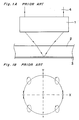
- Fig. 1 shows how reflected light undergoes polarization at respective positions of a bundle of rays when linearly polarized light polarized in the direction of the X-axis is incident upon a prior art magnetooptical disk.
- Fig. 1A is a side elevational view showing a portion in the vicinity of the prior art magnetooptical disk and includes a condenser lens 1, a plastic substrate 2, a recording medium 3 and a light beam 4.
- Fig. 1B is a top plan view of Fig. 1A and shows polarization of reflected light at respective positions of the bundle of rays.
- the linearly polarized light is maintained as it is on the X-axis and the Y-axis but gradually changes elliptically as the position of the bundle of rays is further outwardly displaced in directions forming an angle of 45 degrees with the X-axis and the Y-axis, thereby resulting in deterioration of quality of the reproduced signals.
- an essential object of the present invention is to provide an optical head in which reproduced signals of sufficiently high quality can be obtained even in the case where a plastic substrate is employed, with substantial elimination of the disadvantages inherent in conventional optical heads of this kind.
- an optical head for a magnetooptical disk embodying the present invention comprises a diaphragm for cutting at least an outer portion of a bundle of rays, which is provided in the course of an optical system of a signal detecting portion.
- the optical head K includes a laser diode 11, a condenser lens 12, a half mirror 13, a condenser lens 14, a disk 15, a half mirror 16, an analyzer 17 having an axis of polarization set at an angle of 45 degrees and photodetectors 18 and 19.
- the disk 15 includes a polycarbonate substrate 15a and a recording medium 15b. A bundle of rays introduced by the half mirror 16 is used for a servomechanism of the optical head K. Outputs of the photodetectors 18 and 19 act as reproduced signals.
- the optical head K further includes a light cutting diaphragm 20 for cutting elliptically polarized light referred to earlier.
- the light cutting diaphragm 20 is made of opaque material such as metals, paper, plastics or the like and is interposed between the half mirror 16 and the analyzer 17.
- Figs. 3A and 3B show examples of the light cutting diaphragm 20.
- the light cutting diaphragm 20 is formed with a circular through-hole 21.
- the through-hole 21 has a diameter smaller than an outside diameter (shown by dotted lines) of a light beam 4 so as to cut an outer portion of the bundle of rays, which outer portion changes elliptically.
- Fig. 3A the light cutting diaphragm 20 is formed with a circular through-hole 21.
- the through-hole 21 has a diameter smaller than an outside diameter (shown by dotted lines) of a light beam 4 so as to cut an outer portion of the bundle of rays, which outer portion changes elliptically.
- the light cutting diaphragm 20 is formed with a substantially cross-shaped through-opening 23 defined by four arcuate light cutting portions 22 for cutting four outer portions of the bundle of rays, respectively, which arcuate light cutting portions are diagonally opposed so as to form an angle of 45 degrees with the X-axis and the Y-axis.
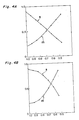
- Fig. 4A is a graph having an ordinate indicative of quantity s of light for signals and modulation degree m of the polycarbonate substrate 15a and an abscissa indicative of a ratio of an area of the through-hole 21 to that of the light beam 4 in the case where the light cutting diaphragm 20 of Fig. 3A is employed.
- an abscissa indicates a ratio of an area of the through-opening 23 to that of the light beam 4 in the case where the light cutting diaphragm 20 of Fig. 3B is employed.
- Figs. 4A is a graph having an ordinate indicative of quantity s of light for signals and modulation degree m of the polycarbonate substrate 15a and an abscissa indicative of a ratio of an area of the through-hole 21 to that of the light beam 4 in the case where the light cutting diaphragm 20 of Fig. 3A is employed.
- an abscissa indicates a ratio of an area of the through-opening 23 to that
- the lens has a numerical aperture (NA) of 0.6, an index n o of double refraction in the direction of the X-axis is 1.585, an index of double refraction in the direction of the Y-axis is (n o +5 ⁇ 10 ⁇ 6), an index of double refraction in the direction of the Z-axis is (n o +6 ⁇ 10 ⁇ 4) and the half-mirror has a transmittance of 0.03. It is seen from Figs. 4A and 4B that the modulation degree m is remarkably increased by cutting the portions of the light beam 4, which are elliptically polarized most.
- NA numerical aperture
- the drop assumes an absolute value on the order of mere several ⁇ W and therefore, does not lead to drop of the S/N as far as an avalanche photodiode is employed as the photodetector.
Landscapes
- Optical Head (AREA)
Abstract
Description
- The present invention relates to an optical head for a magnetooptical disk.
- Recently, much attention is focused, as an erasable optical memory, on a magnetooptical disk. The substrate of the magnetooptical disk is made of glass or plastics. Especially, in view of productivity and easiness of handling, favorable consideration is given to plastics such as acrylic plastic, polycarbonate plastic, etc. However, these plastics are readily subjected to double refraction especially in the case of polycarbonate plastic in comparison with glass and therefore, have optical characteristics inferior to those of glass. Especially, in a disk made of plastic produced by injection molding, double refraction is likely to take place. Meanwhile, in the magnetooptical disk, signals are reproduced by using linearly polarized light. Thus, if double refraction takes place in the substrate of the magnetooptical disk, linearly polarized light is elliptically polarized, thereby resulting in excessive deterioration of quality of the reproduced signals.
- Namely, when signals are actually read from the magnetooptical disk, laser beams are usually transmitted through the substrate by using a lens having a numerical aperture (NA) of 0.5 to 0.6 so as to be condensed. When double refraction takes place in the substrate, linearly polarized light incident upon the substrate is elliptically polarized while being transmitted through the substrate. The above described double refraction is classified into two kinds, i.e. double refraction in the direction of the plane of the substrate and double refraction in a direction perpendicular to the plane of the substrate. It is to be noted here that the double refraction in the direction perpendicular to the plane of the substrate means that there is a difference between a refractive index in the direction perpendicular to the plane of the substrate and that in the direction of the plane of the substrate. Meanwhile, the double refraction in the the plane of the substrate means that there is a difference between refractive indexes in different directions in the plane of the substrate. The double refraction in the direction of the plane of the substrate equally affects polarized light at any position of a bundle of rays. On the other hand, effects of the double refraction in the direction perpendicular to the plane of the substrate, on polarized light varies according to positions in the bundle of rays. Namely, at the center of the bundle of rays, polarized light is incident upon the substrate in a direction approximately perpendicular to the plane of the substrate and therefore, is affected substantially only by the double refraction in the direction of the plane of the substrate so as to be hardly affected by the double refraction in the direction perpendicular to the plane of the substrate. However, since light at an outer portion of the bundle of rays is obliquely incident upon the substrate and thus, is affected by not only the double refraction in the direction of the plane of the substrate but the double refraction in the direction perpendicular to the plane of the substrate.
- Meanwhile, in the case where an orientation of polarized light incident upon the substrate is parallel to or perpendicular to the plane of incidence, linearly polarized light is maintained as it is. A substrate produced by injection molding of polycarbonate plastic has a double refraction in the direction of the plane of the substrate on the order of 10⁻⁶ but has a double refraction in the direction perpendicular to the plane of the substrate on the order of 10⁻⁴ greater by two figures than the double refraction in the direction of the plane of the substrate. Hence, it follows that change of linearly polarized light to elliptically polarized light is mainly caused by the double refraction in the direction perpendicular to the plane of the substrate.
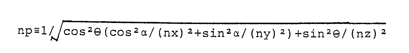
- It is supposed here that a Z-axis is directed in a direction perpendicular to the principal plane of the substrate and an X-axis, a Y-axis and the Z-axis have refractive indexes nx, ny and nz, respectively. Furthermore, assuming that character α denotes an angle formed between the plane of incidence of laser beams and the X-axis and character ϑ denotes an angle of refraction on the substrate, a refractive index ns in the direction perpendicular to the plane of incidence is expressed by the following equation approximately.

- Meanwhile, a refractive index np in the direction of the plane of incidence is given by the equation.
- Fig. 1 shows how reflected light undergoes polarization at respective positions of a bundle of rays when linearly polarized light polarized in the direction of the X-axis is incident upon a prior art magnetooptical disk. Fig. 1A is a side elevational view showing a portion in the vicinity of the prior art magnetooptical disk and includes a
condenser lens 1, aplastic substrate 2, arecording medium 3 and alight beam 4. Fig. 1B is a top plan view of Fig. 1A and shows polarization of reflected light at respective positions of the bundle of rays. The linearly polarized light is maintained as it is on the X-axis and the Y-axis but gradually changes elliptically as the position of the bundle of rays is further outwardly displaced in directions forming an angle of 45 degrees with the X-axis and the Y-axis, thereby resulting in deterioration of quality of the reproduced signals. - Accordingly, an essential object of the present invention is to provide an optical head in which reproduced signals of sufficiently high quality can be obtained even in the case where a plastic substrate is employed, with substantial elimination of the disadvantages inherent in conventional optical heads of this kind.
- In order to accomplish this object of the present invention, an optical head for a magnetooptical disk embodying the present invention comprises a diaphragm for cutting at least an outer portion of a bundle of rays, which is provided in the course of an optical system of a signal detecting portion.
- This object and features of the present invention will become apparent from the following description taken in conjunction with the preferred embodiment thereof with reference to the accompanying drawings, in which:
- Fig. 1A is a side elevational view of a prior art magnetooptical disk (already referred to);
- Fig. 1B is a top plan view of Fig. 1A (already referred to);
- Fig. 2 is a view showing an arrangement of a reproducing optical system of an optical head according to one preferred embodiment of the present invention;
- Figs. 3A and 3B are top plan views showing examples of a light cutting diaphragm employed in the optical head of Fig. 2, respectively; and
- Figs. 4A and 4B are graphs indicative of improvement of modulation degree by the use of the light cutting diaphragms of Figs. 3A and 3B, respectively.
- Before the description of the present invention proceeds, it is to be noted that like parts are designated by like reference numerals throughout several views of the accompanying drawings.
- Referring now to the drawings, there is shown in Fig. 2, an optical head K according to one preferred embodiment of the present invention. The optical head K includes a laser diode 11, a
condenser lens 12, ahalf mirror 13, acondenser lens 14, adisk 15, ahalf mirror 16, ananalyzer 17 having an axis of polarization set at an angle of 45 degrees andphotodetectors disk 15 includes apolycarbonate substrate 15a and arecording medium 15b. A bundle of rays introduced by thehalf mirror 16 is used for a servomechanism of the optical head K. Outputs of thephotodetectors - The optical head K further includes a
light cutting diaphragm 20 for cutting elliptically polarized light referred to earlier. Thelight cutting diaphragm 20 is made of opaque material such as metals, paper, plastics or the like and is interposed between thehalf mirror 16 and theanalyzer 17. - Figs. 3A and 3B show examples of the
light cutting diaphragm 20. In Fig. 3A, thelight cutting diaphragm 20 is formed with a circular through-hole 21. The through-hole 21 has a diameter smaller than an outside diameter (shown by dotted lines) of alight beam 4 so as to cut an outer portion of the bundle of rays, which outer portion changes elliptically. In Fig. 3B, thelight cutting diaphragm 20 is formed with a substantially cross-shaped through-opening 23 defined by four arcuatelight cutting portions 22 for cutting four outer portions of the bundle of rays, respectively, which arcuate light cutting portions are diagonally opposed so as to form an angle of 45 degrees with the X-axis and the Y-axis. - Generally, if reflected light from a disk is elliptically polarized, modulation degree of signals drops, so that noises in the signals increase, thereby resulting in drop of a signal-to-noise ratio (S/N).
- Supposing that a quantity of light for signals and a modulation degree of a glass disk each assume a value of 1, Fig. 4A is a graph having an ordinate indicative of quantity s of light for signals and modulation degree m of the
polycarbonate substrate 15a and an abscissa indicative of a ratio of an area of the through-hole 21 to that of thelight beam 4 in the case where thelight cutting diaphragm 20 of Fig. 3A is employed. Likewise, in Fig. 4B, an abscissa indicates a ratio of an area of the through-opening 23 to that of thelight beam 4 in the case where thelight cutting diaphragm 20 of Fig. 3B is employed. In Figs. 4A and 4B, the lens has a numerical aperture (NA) of 0.6, an index no of double refraction in the direction of the X-axis is 1.585, an index of double refraction in the direction of the Y-axis is (no+5×10⁻⁶), an index of double refraction in the direction of the Z-axis is (no+6×10⁻⁴) and the half-mirror has a transmittance of 0.03. It is seen from Figs. 4A and 4B that the modulation degree m is remarkably increased by cutting the portions of thelight beam 4, which are elliptically polarized most. Although the quantity s of light for signals also drops, the drop assumes an absolute value on the order of mere several µW and therefore, does not lead to drop of the S/N as far as an avalanche photodiode is employed as the photodetector. - As is clear from the foregoing, in accordance with the present invention, it becomes possible to obtain reproduced signals of high quality even in the case where the plastic substrate likely to be subjected to double refraction is employed.
- Although the present invention has been fully described by way of example with reference to the accompanying drawings, it is to be noted here that various changes and modifications will be apparent to those skilled in the art. Therefore, unless otherwise such changes and modifications depart from the scope of the present invention, they should be construed as being included therein.
Claims (3)
a diaphragm (20) for cutting at least an outer portion of a bundle (4) of rays, which is provided in the course of an optical system of a signal detecting portion (17, 18, 19).
Applications Claiming Priority (2)
| Application Number | Priority Date | Filing Date | Title |
|---|---|---|---|
| JP61083916A JP2617176B2 (en) | 1986-04-10 | 1986-04-10 | Light head |
| JP83916/86 | 1986-04-10 |
Publications (3)
| Publication Number | Publication Date |
|---|---|
| EP0241007A2 true EP0241007A2 (en) | 1987-10-14 |
| EP0241007A3 EP0241007A3 (en) | 1989-04-19 |
| EP0241007B1 EP0241007B1 (en) | 1994-01-12 |
Family
ID=13815922
Family Applications (1)
| Application Number | Title | Priority Date | Filing Date |
|---|---|---|---|
| EP87105191A Expired - Lifetime EP0241007B1 (en) | 1986-04-10 | 1987-04-08 | Optical head |
Country Status (4)
| Country | Link |
|---|---|
| US (1) | US4754355A (en) |
| EP (1) | EP0241007B1 (en) |
| JP (1) | JP2617176B2 (en) |
| DE (1) | DE3788743T2 (en) |
Cited By (4)
| Publication number | Priority date | Publication date | Assignee | Title |
|---|---|---|---|---|
| EP0253613A3 (en) * | 1986-07-14 | 1988-11-17 | Sharp Kabushiki Kaisha | Optical head |
| EP0383451A1 (en) * | 1989-02-14 | 1990-08-22 | Sony Corporation | Optical disc recording and reproducing apparatus |
| US5200936A (en) * | 1990-01-09 | 1993-04-06 | International Business Machines Corporation | Magneto-optic method and apparatus for recording and retrieving high-density digital data |
| US7392703B2 (en) | 2004-06-09 | 2008-07-01 | Memsic, Inc. | Z-axis thermal accelerometer |
Families Citing this family (3)
| Publication number | Priority date | Publication date | Assignee | Title |
|---|---|---|---|---|
| JPS62267952A (en) * | 1986-05-16 | 1987-11-20 | Nec Corp | Magneto-optical recording optical head |
| JPH064412Y2 (en) * | 1988-07-27 | 1994-02-02 | パイオニア株式会社 | Optical pickup device |
| US5272684A (en) * | 1989-08-01 | 1993-12-21 | Mitsubishi Denki Kabushiki Kaisha | Information recording method and information recording apparatus for magneto-optic recording information medium |
Family Cites Families (5)
| Publication number | Priority date | Publication date | Assignee | Title |
|---|---|---|---|---|
| US26952A (en) * | 1860-01-24 | George neilson | ||
| USRE26952E (en) | 1961-04-03 | 1970-09-22 | Magnetic reproduce system and method | |
| US3480933A (en) * | 1966-10-12 | 1969-11-25 | Ampex | Spatial filtering noise reduction scheme for a magnetooptic readout system |
| US3739362A (en) * | 1971-03-25 | 1973-06-12 | Magnavox Co | Magneto-optical signal processor |
| JPS62112245A (en) * | 1985-11-12 | 1987-05-23 | Olympus Optical Co Ltd | Recording and reproducing device for optical recording disk |
-
1986
- 1986-04-10 JP JP61083916A patent/JP2617176B2/en not_active Expired - Lifetime
-
1987
- 1987-04-08 EP EP87105191A patent/EP0241007B1/en not_active Expired - Lifetime
- 1987-04-08 DE DE87105191T patent/DE3788743T2/en not_active Expired - Lifetime
- 1987-04-09 US US07/036,427 patent/US4754355A/en not_active Expired - Lifetime
Cited By (5)
| Publication number | Priority date | Publication date | Assignee | Title |
|---|---|---|---|---|
| EP0253613A3 (en) * | 1986-07-14 | 1988-11-17 | Sharp Kabushiki Kaisha | Optical head |
| EP0383451A1 (en) * | 1989-02-14 | 1990-08-22 | Sony Corporation | Optical disc recording and reproducing apparatus |
| US5050145A (en) * | 1989-02-14 | 1991-09-17 | Sony Corporation | Optical disk recording and reproducing apparatus having faster reproducing speed than recording speed |
| US5200936A (en) * | 1990-01-09 | 1993-04-06 | International Business Machines Corporation | Magneto-optic method and apparatus for recording and retrieving high-density digital data |
| US7392703B2 (en) | 2004-06-09 | 2008-07-01 | Memsic, Inc. | Z-axis thermal accelerometer |
Also Published As
| Publication number | Publication date |
|---|---|
| JPS62239452A (en) | 1987-10-20 |
| DE3788743T2 (en) | 1994-04-28 |
| DE3788743D1 (en) | 1994-02-24 |
| US4754355A (en) | 1988-06-28 |
| EP0241007B1 (en) | 1994-01-12 |
| JP2617176B2 (en) | 1997-06-04 |
| EP0241007A3 (en) | 1989-04-19 |
Similar Documents
| Publication | Publication Date | Title |
|---|---|---|
| EP0390610B1 (en) | Optical element and optical pickup device comprising the same | |
| CA1258123A (en) | Read/write head for optical disks | |
| US4971414A (en) | Optical information record/read apparatus | |
| US5621714A (en) | Optical pick-up apparatus having hologram and beam splitter with birefringent member and polarizing film | |
| US6356398B1 (en) | Lens having diaphragm structure at outer edge portion on incident side thereof and optical unit using same | |
| KR100297764B1 (en) | Optical pickup device capable of recording/reproducing with high density | |
| EP0241007A2 (en) | Optical head | |
| US4907858A (en) | Optical pickup apparatus | |
| US5841754A (en) | Optical pickup device having an objective lens and auxiliary lenses exterior thereof | |
| US6278560B1 (en) | Optical scanning device | |
| US5581403A (en) | Beam shaping and beam splitting device and optical head comprising the same | |
| US20010028514A1 (en) | Objective lens, optical pickup device and optical disk device | |
| US5761176A (en) | Optical head device with optically variable aperture for disks with different thicknesses | |
| KR100449612B1 (en) | Optical pickup and opto-magnetic signal reproducing apparatus | |
| US5081614A (en) | Magneto-optical head utilizing central and peripheral portions of reflected light flux for different purposes | |
| JP2878292B2 (en) | Optical head | |
| JPS6326847A (en) | Optical head | |
| US5661701A (en) | Optical pickup using split beams impinging on different photodetector areas | |
| JPH02183125A (en) | Polarization detector and optical head | |
| JPS6320748A (en) | Magneto-optical head | |
| JPH0785523A (en) | Magneto-optical disk device | |
| JP2516926B2 (en) | Magneto-optical head | |
| JPS63181135A (en) | Optical pickup device | |
| JP2001297477A (en) | Integrated unit and optical pickup device using the same | |
| JPH04113526A (en) | Optical pickup |
Legal Events
| Date | Code | Title | Description |
|---|---|---|---|
| PUAI | Public reference made under article 153(3) epc to a published international application that has entered the european phase |
Free format text: ORIGINAL CODE: 0009012 |
|
| 17P | Request for examination filed |
Effective date: 19870408 |
|
| AK | Designated contracting states |
Kind code of ref document: A2 Designated state(s): DE FR GB IT |
|
| PUAL | Search report despatched |
Free format text: ORIGINAL CODE: 0009013 |
|
| AK | Designated contracting states |
Kind code of ref document: A3 Designated state(s): DE FR GB IT |
|
| 17Q | First examination report despatched |
Effective date: 19900808 |
|
| GRAA | (expected) grant |
Free format text: ORIGINAL CODE: 0009210 |
|
| AK | Designated contracting states |
Kind code of ref document: B1 Designated state(s): DE FR GB IT |
|
| REF | Corresponds to: |
Ref document number: 3788743 Country of ref document: DE Date of ref document: 19940224 |
|
| ET | Fr: translation filed | ||
| ITF | It: translation for a ep patent filed | ||
| PLBE | No opposition filed within time limit |
Free format text: ORIGINAL CODE: 0009261 |
|
| STAA | Information on the status of an ep patent application or granted ep patent |
Free format text: STATUS: NO OPPOSITION FILED WITHIN TIME LIMIT |
|
| 26N | No opposition filed | ||
| REG | Reference to a national code |
Ref country code: GB Ref legal event code: IF02 |
|
| PG25 | Lapsed in a contracting state [announced via postgrant information from national office to epo] |
Ref country code: IT Free format text: LAPSE BECAUSE OF NON-PAYMENT OF DUE FEES;WARNING: LAPSES OF ITALIAN PATENTS WITH EFFECTIVE DATE BEFORE 2007 MAY HAVE OCCURRED AT ANY TIME BEFORE 2007. THE CORRECT EFFECTIVE DATE MAY BE DIFFERENT FROM THE ONE RECORDED. Effective date: 20050408 |
|
| APAH | Appeal reference modified |
Free format text: ORIGINAL CODE: EPIDOSCREFNO |
|
| PGFP | Annual fee paid to national office [announced via postgrant information from national office to epo] |
Ref country code: GB Payment date: 20060405 Year of fee payment: 20 |
|
| PGFP | Annual fee paid to national office [announced via postgrant information from national office to epo] |
Ref country code: DE Payment date: 20060406 Year of fee payment: 20 |
|
| PGFP | Annual fee paid to national office [announced via postgrant information from national office to epo] |
Ref country code: FR Payment date: 20060410 Year of fee payment: 20 |
|
| REG | Reference to a national code |
Ref country code: GB Ref legal event code: PE20 |
|
| PG25 | Lapsed in a contracting state [announced via postgrant information from national office to epo] |
Ref country code: GB Free format text: LAPSE BECAUSE OF EXPIRATION OF PROTECTION Effective date: 20070407 |