EP0241002A2 - Process for manufacturing easy-to-open containers - Google Patents
Process for manufacturing easy-to-open containers Download PDFInfo
- Publication number
- EP0241002A2 EP0241002A2 EP87105154A EP87105154A EP0241002A2 EP 0241002 A2 EP0241002 A2 EP 0241002A2 EP 87105154 A EP87105154 A EP 87105154A EP 87105154 A EP87105154 A EP 87105154A EP 0241002 A2 EP0241002 A2 EP 0241002A2
- Authority
- EP
- European Patent Office
- Prior art keywords
- web
- flange
- portions
- die
- cut
- Prior art date
- Legal status (The legal status is an assumption and is not a legal conclusion. Google has not performed a legal analysis and makes no representation as to the accuracy of the status listed.)
- Withdrawn
Links
Images


Classifications
-
- B—PERFORMING OPERATIONS; TRANSPORTING
- B29—WORKING OF PLASTICS; WORKING OF SUBSTANCES IN A PLASTIC STATE IN GENERAL
- B29C—SHAPING OR JOINING OF PLASTICS; SHAPING OF MATERIAL IN A PLASTIC STATE, NOT OTHERWISE PROVIDED FOR; AFTER-TREATMENT OF THE SHAPED PRODUCTS, e.g. REPAIRING
- B29C51/00—Shaping by thermoforming, i.e. shaping sheets or sheet like preforms after heating, e.g. shaping sheets in matched moulds or by deep-drawing; Apparatus therefor
- B29C51/26—Component parts, details or accessories; Auxiliary operations
- B29C51/44—Removing or ejecting moulded articles
- B29C51/445—Removing or ejecting moulded articles from a support after moulding, e.g. by cutting
-
- B—PERFORMING OPERATIONS; TRANSPORTING
- B26—HAND CUTTING TOOLS; CUTTING; SEVERING
- B26F—PERFORATING; PUNCHING; CUTTING-OUT; STAMPING-OUT; SEVERING BY MEANS OTHER THAN CUTTING
- B26F1/00—Perforating; Punching; Cutting-out; Stamping-out; Apparatus therefor
- B26F1/38—Cutting-out; Stamping-out
- B26F1/40—Cutting-out; Stamping-out using a press, e.g. of the ram type
-
- B—PERFORMING OPERATIONS; TRANSPORTING
- B65—CONVEYING; PACKING; STORING; HANDLING THIN OR FILAMENTARY MATERIAL
- B65D—CONTAINERS FOR STORAGE OR TRANSPORT OF ARTICLES OR MATERIALS, e.g. BAGS, BARRELS, BOTTLES, BOXES, CANS, CARTONS, CRATES, DRUMS, JARS, TANKS, HOPPERS, FORWARDING CONTAINERS; ACCESSORIES, CLOSURES, OR FITTINGS THEREFOR; PACKAGING ELEMENTS; PACKAGES
- B65D77/00—Packages formed by enclosing articles or materials in preformed containers, e.g. boxes, cartons, sacks or bags
- B65D77/10—Container closures formed after filling
- B65D77/20—Container closures formed after filling by applying separate lids or covers, i.e. flexible membrane or foil-like covers
- B65D77/2024—Container closures formed after filling by applying separate lids or covers, i.e. flexible membrane or foil-like covers the cover being welded or adhered to the container
- B65D77/2028—Means for opening the cover other than, or in addition to, a pull tab
- B65D77/2032—Means for opening the cover other than, or in addition to, a pull tab by peeling or tearing the cover from the container
- B65D77/2044—Means for opening the cover other than, or in addition to, a pull tab by peeling or tearing the cover from the container whereby a layer of the container or cover fails, e.g. cohesive failure
- B65D77/2048—Means for opening the cover other than, or in addition to, a pull tab by peeling or tearing the cover from the container whereby a layer of the container or cover fails, e.g. cohesive failure whereby part of the container or cover has been weakened, e.g. perforated or precut
- B65D77/2052—Means for opening the cover other than, or in addition to, a pull tab by peeling or tearing the cover from the container whereby a layer of the container or cover fails, e.g. cohesive failure whereby part of the container or cover has been weakened, e.g. perforated or precut the container being weakened
-
- B—PERFORMING OPERATIONS; TRANSPORTING
- B29—WORKING OF PLASTICS; WORKING OF SUBSTANCES IN A PLASTIC STATE IN GENERAL
- B29C—SHAPING OR JOINING OF PLASTICS; SHAPING OF MATERIAL IN A PLASTIC STATE, NOT OTHERWISE PROVIDED FOR; AFTER-TREATMENT OF THE SHAPED PRODUCTS, e.g. REPAIRING
- B29C2793/00—Shaping techniques involving a cutting or machining operation
- B29C2793/0054—Shaping techniques involving a cutting or machining operation partially cutting through the material
-
- B—PERFORMING OPERATIONS; TRANSPORTING
- B65—CONVEYING; PACKING; STORING; HANDLING THIN OR FILAMENTARY MATERIAL
- B65D—CONTAINERS FOR STORAGE OR TRANSPORT OF ARTICLES OR MATERIALS, e.g. BAGS, BARRELS, BOTTLES, BOXES, CANS, CARTONS, CRATES, DRUMS, JARS, TANKS, HOPPERS, FORWARDING CONTAINERS; ACCESSORIES, CLOSURES, OR FITTINGS THEREFOR; PACKAGING ELEMENTS; PACKAGES
- B65D2577/00—Packages formed by enclosing articles or materials in preformed containers, e.g. boxes, cartons, sacks, bags
- B65D2577/10—Container closures formed after filling
- B65D2577/20—Container closures formed after filling by applying separate lids or covers
- B65D2577/2075—Lines of weakness or apertures
- B65D2577/2083—Lines of weakness or apertures in container flange
Definitions
- the present invention relates to a process for manufacturing easy-to-open containers comprising a plastic cup body formed with a flange, and a lid member, particularly a container in which the outer peripheral portion of the flange and the lid member can be peeled off the cup body at a time to open the container.
- a conventional easy-to-open container of this type comprises a plastic cup body having a flange, and a lid member in the form of a film formed with a tongue portion for opening which protrudes over the flange.
- the periphery of the lid is heat-sealed to the flange after packing a foodstuff in the cup body.
- the lid is adapted to be peeled off the flange by holding and pulling up the tongue protruding from a part of the periphery of the flange.
- the tip of the tongue is firstly bent up to cut off a thin portion left uncut at a V-cut formed in the bottom surface of the tongue at its tip, and then the lid is peeled off the flange by pulling the tip of the lid together with the tongue which has been separated from the remaining flange portion.
- the lid When the lid is pulled up to open the container, the lid stretches by the pulling force. Also, because of its limpness, the pulling force does not effectively act on the sealed portion between the flange and the lid. Consequently, it is impossible to obtain a stable easiness to open.
- A designates a cup body comprising a bottom wall 1, a peripheral wall 2 integral with the bottom wall 1, and a flange 3 outwardly protruding from the edge of the peripheral wall 2.
- the flange 3 is formed with cut-through portions 5 and partially cut portions 4 alternating along the edge of the peripheral wall 2.
- the die-cutting of the cup body from the web and the formation of the cut-through portions and the partially cut portions are carried out at one time.
- a web 11 of synthetic resin is fed intermittently. While the web 11 is stopping, a male mold 12 and a female mold 13 arranged on both sides of the web 11 press the web 11 to form a cup body A with the peripheral wall 2 and the bottom wall 1 protruding toward one side of the web 11.
- a die-cutting knife 14 is lowered to die-cut the cup body A from the web 11 so that the outwardly protruding flange portion 3 will be formed at the edge of the peripheral wall 2.
- Another die-cutting knife 15 is arranged inside the die-cutting knife 14. This knife 15 is lowered simultaneously with the knife 14 to form the cut-through portions 5 alternating with partially cut portions 4 in the flange 3 along the edge of the peripheral wall 2.
- the die-cutting of the cup body from the web and the formation of the cut-through portions and the partially cut portions are carried out separately.
- the male mold 12 and the female mold 13 opposed to each other press the web 11 to form the cup body A with the peripheral wall 2 and the bottom wall 1 protruding toward one side of the web 11 as in the first embodiment.
- the die-cutting knife 15 is lowered to form the cut-through portions 5 alternating with the partially cut portions 4 in the flange 3 along the edge of the peripheral wall 2.
- the cup body A is held in position by a mold 16 inserted therein.
- the cup body A formed with the cut-through portions 5 is fed forward and stopped, where the die-cutting knife 14 is lowered to die-cut the cup body A from the web 11 with the flange 3 protruding from the edge of the peripheral wall 2.
- the die-cutting of the cup bodies from the web is carried out, after which the cut-through portions and the partially cut portions are formed off the web line.
- the male mold 12 and the female mold 13 opposed to each other press the web 11 to form the cup body A as in the first embodiment.
- the die-cutting knife 14 is lowered to die-cut the cup body A formed with the flange 3. Thereafter, each die-cut cup body A is put on the mold 16, and the die-cutting knife 15 forms the cut-through portions 5 alternating with the partially cut portions 4 in the flange 3.
- the cup body A formed in a strip not in a web in the same manner as above is die-cut by the die-cutting knife 14 with the flange portion 3 and at the same time the die-cutting knife 15 forms the cut-through portions 5 alternating with the partially cut portions 4.
- the web 11 is die-cut by the die-cutting knives 14 and 15 when a body 17 lowers by a predetermined distance.
- cutouts 18 are formed at the tip of the die-cutting knives 15.
- a lid B the periphery of which is heat-sealed to or secured with an adhesive to the flange 3.
- portion 3 ⁇ outside of the cut-through portions 5 can be separated from the flange 3 by pulling it up. Together with the portion 3 ⁇ , the lid B can be peeled easily.
- Figs. 16 and 17 show the fifth embodiment in which six cut-through portions 5 and six partially cut portions 4 are formed alternately along the edge of a flange portion 3 having a thickness of 0.8 mm.
- the partially cut portions 4 have a thickness of about 0.05 mm.
- the portion outside of the cut-through portions 5 is removed when opening the container.
- a support 19 formed with six recesses 20, 0.05 mm in depth and 3 mm in width was used to form partially cut portions 5 instead of using the die-cutting knife 15 formed with a cutout 18.
- a horizontal Thomson knife 21 was used as shown in Fig. 17.
- the cut-through portions 5 as well as the partially cut portions 4 were very precisely formed, and the portion outside of the cut-through portions 5 was readily removed. It was also possible to die-cut a plurality of cup bodies A at a time without any trouble.
Landscapes
- Engineering & Computer Science (AREA)
- Mechanical Engineering (AREA)
- Life Sciences & Earth Sciences (AREA)
- Forests & Forestry (AREA)
- Blow-Moulding Or Thermoforming Of Plastics Or The Like (AREA)
- Containers Having Bodies Formed In One Piece (AREA)
- Packages (AREA)
- Moulds For Moulding Plastics Or The Like (AREA)
Abstract
Description
- The present invention relates to a process for manufacturing easy-to-open containers comprising a plastic cup body formed with a flange, and a lid member, particularly a container in which the outer peripheral portion of the flange and the lid member can be peeled off the cup body at a time to open the container.
- A conventional easy-to-open container of this type comprises a plastic cup body having a flange, and a lid member in the form of a film formed with a tongue portion for opening which protrudes over the flange. The periphery of the lid is heat-sealed to the flange after packing a foodstuff in the cup body. In one prior art container, the lid is adapted to be peeled off the flange by holding and pulling up the tongue protruding from a part of the periphery of the flange. In another prior art container, the tip of the tongue is firstly bent up to cut off a thin portion left uncut at a V-cut formed in the bottom surface of the tongue at its tip, and then the lid is peeled off the flange by pulling the tip of the lid together with the tongue which has been separated from the remaining flange portion.
- When the lid is pulled up to open the container, the lid stretches by the pulling force. Also, because of its limpness, the pulling force does not effectively act on the sealed portion between the flange and the lid. Consequently, it is impossible to obtain a stable easiness to open.
- In accordance with the present invention, easy-to-open containers can be mass-produced extremely easily. In the flange of each cup body, cut-through portions and partially cut portions are formed alternately. This ensures that an outer peripheral portion of the flange can be easily peeled off the cup body together with the lid of the container. The die-cutting of the cup bodies from an intermittently fed web and the formation of the cut-through portions and the partially cut portions may be carried out either at a time or one after the other.
- Other features and objects of the present invention will become apparent from the following description with reference to the accompanying drawings, in which:
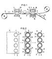
- Fig. 1 is a side view of an apparatus for the first embodiment of the present invention;
- Fig. 2 is a plan view of the same;
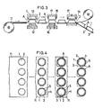
- Fig. 3 is a side view of an apparatus for the second embodiment;
- Fig. 4 is a plan view of the same;
- Fig. 5. is a side view of an apparatus for the third embodiment;
- Fig. 6 is a plan view of the same;
- Fig. 7 is a side view of an apparatus for the fourth embodiment of the present invention;
- Fig. 8 is a plan view of the same;
- Figs. 9 through 11 are enlarged vertical sectional front views of die-cutting knives;
- Fig. 12 is a side view of a die-cutting knife;
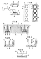
- Fig. 13 is a plan view of a cup body;
- Fig. 14 is a perspective view of the same; and
- Fig. 15 is a vertical sectional side view of the same with the lid half-open;
- Fig. 16 is a perspective view of the support used in the fifth embodiment; and
- Fig. 17 is a vertical sectional view showing the fifth embodiment.
- In the drawings, A designates a cup body comprising a
bottom wall 1, aperipheral wall 2 integral with thebottom wall 1, and aflange 3 outwardly protruding from the edge of theperipheral wall 2. Theflange 3 is formed with cut-throughportions 5 and partially cutportions 4 alternating along the edge of theperipheral wall 2. - Next, a process for manufacturing the cup bodies A will be described with reference to the accompanying drawings.
- In the first embodiment shown in Figs. 1 and 2, the die-cutting of the cup body from the web and the formation of the cut-through portions and the partially cut portions are carried out at one time. A
web 11 of synthetic resin is fed intermittently. While theweb 11 is stopping, amale mold 12 and afemale mold 13 arranged on both sides of theweb 11 press theweb 11 to form a cup body A with theperipheral wall 2 and thebottom wall 1 protruding toward one side of theweb 11. - When each cup body A comes to a next station, a die-
cutting knife 14 is lowered to die-cut the cup body A from theweb 11 so that the outwardly protrudingflange portion 3 will be formed at the edge of theperipheral wall 2. - Another die-
cutting knife 15 is arranged inside the die-cutting knife 14. Thisknife 15 is lowered simultaneously with theknife 14 to form the cut-throughportions 5 alternating with partially cutportions 4 in theflange 3 along the edge of theperipheral wall 2. - In the second embodiment shown in Figs. 3 and 4, the die-cutting of the cup body from the web and the formation of the cut-through portions and the partially cut portions are carried out separately. When the
web 11 intermittently fed is at a stop, themale mold 12 and thefemale mold 13 opposed to each other press theweb 11 to form the cup body A with theperipheral wall 2 and thebottom wall 1 protruding toward one side of theweb 11 as in the first embodiment. - When the cup body A comes to a next station, the die-
cutting knife 15 is lowered to form the cut-throughportions 5 alternating with the partially cutportions 4 in theflange 3 along the edge of theperipheral wall 2. When die-cutting, the cup body A is held in position by amold 16 inserted therein. - The cup body A formed with the cut-through
portions 5 is fed forward and stopped, where the die-cutting knife 14 is lowered to die-cut the cup body A from theweb 11 with theflange 3 protruding from the edge of theperipheral wall 2. - In the third embodiment shown in Figs. 5 and 6, the die-cutting of the cup bodies from the web is carried out, after which the cut-through portions and the partially cut portions are formed off the web line. When the
web 11 intermittently fed is at a stop, themale mold 12 and thefemale mold 13 opposed to each other press theweb 11 to form the cup body A as in the first embodiment. - When the cup body A comes to a stop again at the next station, the die-
cutting knife 14 is lowered to die-cut the cup body A formed with theflange 3. Thereafter, each die-cut cup body A is put on themold 16, and the die-cutting knife 15 forms the cut-throughportions 5 alternating with the partially cutportions 4 in theflange 3. - In the fourth embodiment shown in Figs. 7 and 8, the cup body A formed in a strip not in a web in the same manner as above is die-cut by the die-
cutting knife 14 with theflange portion 3 and at the same time the die-cutting knife 15 forms the cut-throughportions 5 alternating with the partially cutportions 4. - As shown in Figs. 9 to 12, the
web 11 is die-cut by the die-cutting knives body 17 lowers by a predetermined distance. In order to form the partially cutportions 4,cutouts 18 are formed at the tip of the die-cutting knives 15. - After the cup body A shown in Fig. 14 has been packed with a desired foodstuff, it is covered by a lid B, the periphery of which is heat-sealed to or secured with an adhesive to the
flange 3. - When opening, portion 3ʹ outside of the cut-through
portions 5 can be separated from theflange 3 by pulling it up. Together with the portion 3ʹ, the lid B can be peeled easily. - If the web is heated beforehand, there is no need for heating the male and female molds. If not, they should be heated.
- Figs. 16 and 17 show the fifth embodiment in which six cut-through
portions 5 and six partially cutportions 4 are formed alternately along the edge of aflange portion 3 having a thickness of 0.8 mm. The partially cutportions 4 have a thickness of about 0.05 mm. - The portion outside of the cut-through
portions 5 is removed when opening the container. In this embodiment, as shown in Fig. 16, asupport 19 formed with sixrecesses 20, 0.05 mm in depth and 3 mm in width was used to form partially cutportions 5 instead of using the die-cutting knife 15 formed with acutout 18. For cutting, a horizontal Thomsonknife 21 was used as shown in Fig. 17. The cut-throughportions 5 as well as the partially cutportions 4 were very precisely formed, and the portion outside of the cut-throughportions 5 was readily removed. It was also possible to die-cut a plurality of cup bodies A at a time without any trouble.
Claims (5)
Applications Claiming Priority (4)
| Application Number | Priority Date | Filing Date | Title |
|---|---|---|---|
| JP7825786 | 1986-04-07 | ||
| JP78257/86 | 1986-04-07 | ||
| JP91119/86 | 1986-04-16 | ||
| JP61091119A JPS62244612A (en) | 1986-04-16 | 1986-04-16 | Manufacture of easily openable vessel |
Publications (2)
| Publication Number | Publication Date |
|---|---|
| EP0241002A2 true EP0241002A2 (en) | 1987-10-14 |
| EP0241002A3 EP0241002A3 (en) | 1989-07-12 |
Family
ID=26419340
Family Applications (1)
| Application Number | Title | Priority Date | Filing Date |
|---|---|---|---|
| EP87105154A Withdrawn EP0241002A3 (en) | 1986-04-07 | 1987-04-07 | Process for manufacturing easy-to-open containers |
Country Status (1)
| Country | Link |
|---|---|
| EP (1) | EP0241002A3 (en) |
Cited By (9)
| Publication number | Priority date | Publication date | Assignee | Title |
|---|---|---|---|---|
| US4865217A (en) * | 1987-08-31 | 1989-09-12 | Sumitomo Bakelite Company, Limited | Easily openable sealed container |
| WO1997048544A1 (en) * | 1996-06-20 | 1997-12-24 | Tetra Laval Holdings & Finance S.A. | Device for making concave covers from a plastic foil strip |
| FR2755427A1 (en) * | 1996-11-04 | 1998-05-07 | Erca | Container with re=closable lid, e.g. for liquid or powdered products |
| DE29911270U1 (en) * | 1999-06-30 | 2000-11-16 | Stefan Maier Werkzeugbau und Maschinenbau GmbH, 83224 Grassau | Machine for deep-drawing cup-shaped containers in a plastic film web |
| CN106273371A (en) * | 2016-08-05 | 2017-01-04 | 安庆博美塑业有限公司 | A kind of plastic packing box automatic compression molding and feeding device |
| CN109130228A (en) * | 2018-08-15 | 2019-01-04 | 张仁贵 | A kind of manufacture craft and easy open cover of easy open cover |
| CN109850207A (en) * | 2017-11-30 | 2019-06-07 | 内蒙古伊利实业集团股份有限公司 | A kind of processing method and processing unit (plant) of the cup facilitating unlatching |
| EP4656356A1 (en) * | 2019-02-06 | 2025-12-03 | Berry Global, Inc. | Process of forming polymeric material |
| US12515416B2 (en) | 2017-08-07 | 2026-01-06 | Berry Global, Inc. | Method and apparatus for thermoforming an article |
Family Cites Families (3)
| Publication number | Priority date | Publication date | Assignee | Title |
|---|---|---|---|---|
| US3108708A (en) * | 1959-11-10 | 1963-10-29 | Plastomatic Corp | Sealed plastic containers |
| EP0305714A3 (en) * | 1983-10-06 | 1989-09-06 | Servichem AG | Device for moulding articles made of thermoplastic material |
| FR2559366A1 (en) * | 1984-02-10 | 1985-08-16 | Delgrande Lorenzo | Removable rim on plastic containers |
-
1987
- 1987-04-07 EP EP87105154A patent/EP0241002A3/en not_active Withdrawn
Cited By (9)
| Publication number | Priority date | Publication date | Assignee | Title |
|---|---|---|---|---|
| US4865217A (en) * | 1987-08-31 | 1989-09-12 | Sumitomo Bakelite Company, Limited | Easily openable sealed container |
| WO1997048544A1 (en) * | 1996-06-20 | 1997-12-24 | Tetra Laval Holdings & Finance S.A. | Device for making concave covers from a plastic foil strip |
| FR2755427A1 (en) * | 1996-11-04 | 1998-05-07 | Erca | Container with re=closable lid, e.g. for liquid or powdered products |
| DE29911270U1 (en) * | 1999-06-30 | 2000-11-16 | Stefan Maier Werkzeugbau und Maschinenbau GmbH, 83224 Grassau | Machine for deep-drawing cup-shaped containers in a plastic film web |
| CN106273371A (en) * | 2016-08-05 | 2017-01-04 | 安庆博美塑业有限公司 | A kind of plastic packing box automatic compression molding and feeding device |
| US12515416B2 (en) | 2017-08-07 | 2026-01-06 | Berry Global, Inc. | Method and apparatus for thermoforming an article |
| CN109850207A (en) * | 2017-11-30 | 2019-06-07 | 内蒙古伊利实业集团股份有限公司 | A kind of processing method and processing unit (plant) of the cup facilitating unlatching |
| CN109130228A (en) * | 2018-08-15 | 2019-01-04 | 张仁贵 | A kind of manufacture craft and easy open cover of easy open cover |
| EP4656356A1 (en) * | 2019-02-06 | 2025-12-03 | Berry Global, Inc. | Process of forming polymeric material |
Also Published As
| Publication number | Publication date |
|---|---|
| EP0241002A3 (en) | 1989-07-12 |
Similar Documents
| Publication | Publication Date | Title |
|---|---|---|
| US4246288A (en) | Reclosable package | |
| US4240241A (en) | Method and apparatus for making a reclosable package | |
| US4787552A (en) | Case for packaging | |
| US4155692A (en) | Shear molding of reinforced latch | |
| EP0241002A2 (en) | Process for manufacturing easy-to-open containers | |
| US4006818A (en) | Packaging shell with hinged bottom wall | |
| US4749097A (en) | Two section bakery container | |
| EP0816239A1 (en) | Packaging container and tool for the manufacture thereof | |
| US7628950B2 (en) | Method and tooling for slitting a thermoformed container and container formed thereby | |
| EP0748746A1 (en) | Easy-to-open thermoplastic package | |
| US10875671B2 (en) | Blister packaging machine | |
| GB1580791A (en) | Blister packs | |
| EP0380250B1 (en) | Improvements in or relating to thermoformed articles | |
| JPH0369461A (en) | Thermo-contractive lid and its production | |
| EP0426009B1 (en) | Multilayer plastics containers and methods of producing the same | |
| US6565688B2 (en) | Angular border on three dimensional sheet material and method of producing | |
| JPH0555393B2 (en) | ||
| JP2003246320A (en) | Corrugated board box with tear tape and its manufacturing method | |
| JPH0140870Y2 (en) | ||
| ES8406935A1 (en) | Process and apparatus for producing plastics articles interconnected by easily breakable seams by way of thermoforming. | |
| JPH0343184Y2 (en) | ||
| EP2978681B1 (en) | Container for use with opening means | |
| JP2521443B2 (en) | Method of cutting a molded product from a plate-shaped material | |
| JPS5911069Y2 (en) | packaging box body | |
| JP2914750B2 (en) | Method of manufacturing easy-open lid |
Legal Events
| Date | Code | Title | Description |
|---|---|---|---|
| PUAI | Public reference made under article 153(3) epc to a published international application that has entered the european phase |
Free format text: ORIGINAL CODE: 0009012 |
|
| AK | Designated contracting states |
Kind code of ref document: A2 Designated state(s): DE FR SE |
|
| PUAL | Search report despatched |
Free format text: ORIGINAL CODE: 0009013 |
|
| AK | Designated contracting states |
Kind code of ref document: A3 Designated state(s): DE FR SE |
|
| 17P | Request for examination filed |
Effective date: 19891013 |
|
| 17Q | First examination report despatched |
Effective date: 19910805 |
|
| STAA | Information on the status of an ep patent application or granted ep patent |
Free format text: STATUS: THE APPLICATION HAS BEEN WITHDRAWN |
|
| 18W | Application withdrawn |
Withdrawal date: 19911121 |
|
| R18W | Application withdrawn (corrected) |
Effective date: 19911121 |
|
| RIN1 | Information on inventor provided before grant (corrected) |
Inventor name: KANEKO, FUMIHIKO Inventor name: YOSHIMURA, KANJI |