EP0240891A2 - Sicherheitsvorrichtung, um ein Reifenventil an einem Druckmesser anzuschliessen für Maximum- und Minimum-Drucksignal-"Onboard"-Relaissysteme - Google Patents
Sicherheitsvorrichtung, um ein Reifenventil an einem Druckmesser anzuschliessen für Maximum- und Minimum-Drucksignal-"Onboard"-Relaissysteme Download PDFInfo
- Publication number
- EP0240891A2 EP0240891A2 EP87104672A EP87104672A EP0240891A2 EP 0240891 A2 EP0240891 A2 EP 0240891A2 EP 87104672 A EP87104672 A EP 87104672A EP 87104672 A EP87104672 A EP 87104672A EP 0240891 A2 EP0240891 A2 EP 0240891A2
- Authority
- EP
- European Patent Office
- Prior art keywords
- connecting portion
- tire valve
- stem
- pressure detector
- ring nut
- Prior art date
- Legal status (The legal status is an assumption and is not a legal conclusion. Google has not performed a legal analysis and makes no representation as to the accuracy of the status listed.)
- Withdrawn
Links
Images
Classifications
-
- B—PERFORMING OPERATIONS; TRANSPORTING
- B60—VEHICLES IN GENERAL
- B60C—VEHICLE TYRES; TYRE INFLATION; TYRE CHANGING; CONNECTING VALVES TO INFLATABLE ELASTIC BODIES IN GENERAL; DEVICES OR ARRANGEMENTS RELATED TO TYRES
- B60C23/00—Devices for measuring, signalling, controlling, or distributing tyre pressure or temperature, specially adapted for mounting on vehicles; Arrangement of tyre inflating devices on vehicles, e.g. of pumps or of tanks; Tyre cooling arrangements
- B60C23/02—Signalling devices actuated by tyre pressure
- B60C23/04—Signalling devices actuated by tyre pressure mounted on the wheel or tyre
- B60C23/0408—Signalling devices actuated by tyre pressure mounted on the wheel or tyre transmitting the signals by non-mechanical means from the wheel or tyre to a vehicle body mounted receiver
Definitions
- the present invention relates to a safety device for connecting a tire valve to a pressure detector of onboard maximum and minimum pressure signal relay systems.
- Systems are known for relaying or transmitting, on board of motor vehicles, abnormal conditions of the tires - in particular overpressure and underpressure - based on the radio relaying of signals emitted by a pressure detector, which signals, received and discriminated by a radio receiver placed in the cabin of interior compartment of the motor vehicle, activate one or more alarm detectors.
- the pressure detector is generally accommodated, together with the radio transmitter, in a container which is sealed and made watertight by a resin treatment, suitable for being stably coupled to the tire rim, generally on the wheel hub to avoid dynamic unbalances.
- a normal tube provided with a ring nut coupling, pneumatically connects the detector to the tire valve, transmitting the pressure of the latter to the former.
- the tire valve must be disabled, and this is achieved by means of a push rod in the ring nut coupling, suitable for pushing against the stem of the valve to push it into the open position when the ring nut is screwed on to the seat of the usual valve cap, in replacement thereof.
- the present invention is essentially intended to eliminate this disadvantage by providing a safety connection which is suitable for allowing the normal action of the tire valve in case of breakage of, or damage to, the connecting tube and/or the pressure detector.
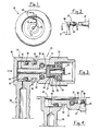
- the reference numeral 10 indicates the wheel of a motor vehicle
- 11 indicates a container comprising the pressure detector and the radio transmitter of the maximum and minimum pressure onboard relay system
- 12 indicates the connecting tube for pneumatic connecting the detector to the tire valve 21
- 20 indicates the safety connecting device object of the present invention.
- the device 20 comprises a first connecting portion composed of a ring nut 22 which can be threadingly coupled to the threaded end of the valve 21 in replacement of the usual closing cap.
- the ring nut 22 contains a pusher body having a rigid pusher rod 23 suitable for engaging the stem (not illustrated) of the valve 21 to push it into its open position when the ring 22 is fully screwed onto the same valve.
- the pusher rod 23 is provided with an air pressure cavity 24 extending also in a wider base 25 of the pusher body, on which a sealing gasket 26 abuts.
- the base 25 further defines an annular throat 27 accommodating a second OR type sealing gasket 28.
- Radial channels 29 for the passage of air are provided on the face of the base 25 which is opposite to the pusher rod 23, and communicate with the cavity 24 of the pusher rod.
- the base 25 defines, on one side, an airtight cylindrical chamber 30, in which a sealing disk 31 of light material, advantageously plastic material, is contained freely movable for separating from each other two parts of the chamber 30.
- the disk 31 is movable between two extreme positions, respectively for airflow passage and cutoff and is provided with a diameter which is slightly smaller than the chamber 30, so that an adequate annular port is defined between the wall of the chamber 30 and the disk 31, for the passage of air from the chamber part facing the base 25 to the other chamber part.
- the extreme air passage position is defined by the abutment of one side of the disk 31 against the base 25 of the pusher body (Fig. 3).
- the cutoff position is defined by the abutment of the other side of the disk 31 against an OR type gasket 32 accommodated in an annular seat of the chamber 30 (Fig.4).
- the ring nut 22 extends into a stem 33 defining a throat 34 and an annular seat 35 for the accommodation of an OR gasket 36.
- a second connecting portion 37 of the device 20 is fitted onto the stem 33, and comprises a head 38 and a connector 39 for coupling with the small tube 12, the connector being in any way angled with respect to the axis of the ring 22.
- the head 38 can rotate and axially and sealingly slide on the stem 33 by an amount matching the width of the throat 34, by virtue of the engagement of a stop tab 40, extending within the throat 34, with the shoulder of the latter.
- a through axial cavity 41 is provided in the stem 33 and accommodates, axially slideable therein, a pusher rod 42, the ends whereof are intended to abut on one side against the inner wall of the head 38, on the other side against the sealing disk 31.
- the arrangement is thus such that by pressing on the head 38 of the second connecting portion, the disk 31 is caused to move away from the cutoff position, in which the disk 31 abuts against the gasket 32.
- the diameter of the stem 42 is slightly smaller than the diameter of the axial cavity 41 so that a port for the passage of air is defined between the the stem 42 and the axial cavity 41.
- the operation of the device is as follows: By screwing the ring nut 22 on the valve 21, the pusher rod 23 - pushing the stem of the latter - causes compressed air to enter the chamber 30, flowing through the air passage cavity 24 and the channels 29. The compressed air pushes the disk 31 in the cutoff position against the gasket 32, blocking the outflow. In this condition, to allow the air to reach the pressure system detector, it is necessary to press on the head 38 to thereby shift the disk 31 away from the gasket 32 torward or against the base 25 of the pusher body.
- the pressure in the two parts of the chamber 30, separated by the disk 31, is equalized and the disk remains in a neutral position for any variation of the pressure inside the tire, allowing transmission of pressure variations to the detection device. If conversely a leak occurs in the connecting tube 12 and/or in the detection device, the pressure within the chamber 30 becomes unbalanced and the disk 31 is pushed against the gasket 32 cutting off the airflow caused by said leak.
Landscapes
- Engineering & Computer Science (AREA)
- Mechanical Engineering (AREA)
- Measuring Fluid Pressure (AREA)
Applications Claiming Priority (2)
| Application Number | Priority Date | Filing Date | Title |
|---|---|---|---|
| IT5323986U | 1986-04-08 | ||
| IT5323986U IT207785Z2 (it) | 1986-04-08 | 1986-04-08 | Dispositivo di sicurezza per il raccordo della valvola dei pneumatici di autoveicoli al rilevatore di pressione dei sistemi di ripetizione a bordo della segnalazione di massima e minima pressione |
Publications (2)
| Publication Number | Publication Date |
|---|---|
| EP0240891A2 true EP0240891A2 (de) | 1987-10-14 |
| EP0240891A3 EP0240891A3 (de) | 1989-07-12 |
Family
ID=11281124
Family Applications (1)
| Application Number | Title | Priority Date | Filing Date |
|---|---|---|---|
| EP87104672A Withdrawn EP0240891A3 (de) | 1986-04-08 | 1987-03-30 | Sicherheitsvorrichtung, um ein Reifenventil an einem Druckmesser anzuschliessen für Maximum- und Minimum-Drucksignal-"Onboard"-Relaissysteme |
Country Status (2)
| Country | Link |
|---|---|
| EP (1) | EP0240891A3 (de) |
| IT (1) | IT207785Z2 (de) |
Cited By (2)
| Publication number | Priority date | Publication date | Assignee | Title |
|---|---|---|---|---|
| EP1248091A1 (de) * | 2001-04-02 | 2002-10-09 | Huba Control Ag | Ausströmsicherung |
| CN106314573A (zh) * | 2016-08-22 | 2017-01-11 | 江西惠当家信息技术股份有限公司 | 一种主动扎破对侧胎来保持车辆爆胎后车身稳定的方法 |
Family Cites Families (1)
| Publication number | Priority date | Publication date | Assignee | Title |
|---|---|---|---|---|
| SE7902187L (sv) * | 1979-03-12 | 1980-09-13 | Siemens Elema Ab | Anordning for overvakning av ringtryck hos hjul pa ett fordon |
-
1986
- 1986-04-08 IT IT5323986U patent/IT207785Z2/it active
-
1987
- 1987-03-30 EP EP87104672A patent/EP0240891A3/de not_active Withdrawn
Cited By (2)
| Publication number | Priority date | Publication date | Assignee | Title |
|---|---|---|---|---|
| EP1248091A1 (de) * | 2001-04-02 | 2002-10-09 | Huba Control Ag | Ausströmsicherung |
| CN106314573A (zh) * | 2016-08-22 | 2017-01-11 | 江西惠当家信息技术股份有限公司 | 一种主动扎破对侧胎来保持车辆爆胎后车身稳定的方法 |
Also Published As
| Publication number | Publication date |
|---|---|
| IT8653239V0 (it) | 1986-04-08 |
| IT207785Z2 (it) | 1988-02-15 |
| EP0240891A3 (de) | 1989-07-12 |
Similar Documents
| Publication | Publication Date | Title |
|---|---|---|
| US4975679A (en) | Pressure sensor system | |
| US5584949A (en) | Air inflation system for trailer axles | |
| CA2728611C (en) | Pressure controlled three way valve device | |
| US20080185086A1 (en) | Rotary Union Assembly For Use In Air Pressure Inflation Systems For Tractor Trailer Tires | |
| EA199700108A1 (ru) | Ниппель | |
| US20050115655A1 (en) | Expandable spindle plug assembly for use with automatic tire inflation systems | |
| MXPA00011195A (es) | Junta giratoria para sistema de inflado con aire. | |
| US10661612B2 (en) | Wheel valve arrangement and tire pressure control system having at least one such wheel valve arrangement | |
| US5055826A (en) | Pressure sensor system | |
| CA1090204A (en) | Acoustical tire pressure valve | |
| US6497262B1 (en) | Automobile wheel unit with tire inflation system | |
| EP0240891A2 (de) | Sicherheitsvorrichtung, um ein Reifenventil an einem Druckmesser anzuschliessen für Maximum- und Minimum-Drucksignal-"Onboard"-Relaissysteme | |
| US3982225A (en) | Pneumatic switch for low tire pressure warning system | |
| US2633889A (en) | Means for checking and adjusting the air pressure in tires | |
| US4781209A (en) | Switch-over valve, preferably for an air drier | |
| US11318800B1 (en) | Pressurizable adapter of bicycle valve | |
| US5101754A (en) | Device for surveillance of a pressure in a vehicle tire | |
| US2633148A (en) | Tire pressure relief valve | |
| KR910019844A (ko) | 차량 브레이크 시스템용 공압부우스터 | |
| US4991618A (en) | Air pressure indication and control system for a tire stem air valve | |
| US3542110A (en) | Valve means for multi-chamber pneumatic tire | |
| US3532116A (en) | Brake cylinder pressure retaining valve | |
| US4421052A (en) | Tire pressure signalling device | |
| US4601254A (en) | Tire pressure warning device | |
| GB2201755A (en) | Pressure equilibrating and/or safety device for fluid systems, particularly for motor vehicle tyres |
Legal Events
| Date | Code | Title | Description |
|---|---|---|---|
| PUAI | Public reference made under article 153(3) epc to a published international application that has entered the european phase |
Free format text: ORIGINAL CODE: 0009012 |
|
| AK | Designated contracting states |
Kind code of ref document: A2 Designated state(s): DE ES FR GB |
|
| PUAL | Search report despatched |
Free format text: ORIGINAL CODE: 0009013 |
|
| AK | Designated contracting states |
Kind code of ref document: A3 Designated state(s): DE ES FR GB |
|
| 17P | Request for examination filed |
Effective date: 19890929 |
|
| 17Q | First examination report despatched |
Effective date: 19900802 |
|
| STAA | Information on the status of an ep patent application or granted ep patent |
Free format text: STATUS: THE APPLICATION IS DEEMED TO BE WITHDRAWN |
|
| 18D | Application deemed to be withdrawn |
Effective date: 19910323 |
|
| RIN1 | Information on inventor provided before grant (corrected) |
Inventor name: MONDARDINI, MASSIMO |