EP0240733A2 - Method and controller for controlling a mechanical manipulator - Google Patents
Method and controller for controlling a mechanical manipulator Download PDFInfo
- Publication number
- EP0240733A2 EP0240733A2 EP87103172A EP87103172A EP0240733A2 EP 0240733 A2 EP0240733 A2 EP 0240733A2 EP 87103172 A EP87103172 A EP 87103172A EP 87103172 A EP87103172 A EP 87103172A EP 0240733 A2 EP0240733 A2 EP 0240733A2
- Authority
- EP
- European Patent Office
- Prior art keywords
- motion
- attributes
- procedure
- robot
- attribute
- Prior art date
- Legal status (The legal status is an assumption and is not a legal conclusion. Google has not performed a legal analysis and makes no representation as to the accuracy of the status listed.)
- Granted
Links
Images


Classifications
-
- G—PHYSICS
- G05—CONTROLLING; REGULATING
- G05B—CONTROL OR REGULATING SYSTEMS IN GENERAL; FUNCTIONAL ELEMENTS OF SUCH SYSTEMS; MONITORING OR TESTING ARRANGEMENTS FOR SUCH SYSTEMS OR ELEMENTS
- G05B19/00—Program-control systems
- G05B19/02—Program-control systems electric
- G05B19/42—Recording and playback systems, i.e. in which the program is recorded from a cycle of operations, e.g. the cycle of operations being manually controlled, after which this record is played back on the same machine
- G05B19/427—Teaching successive positions by tracking the position of a joystick or handle to control the positioning servo of the tool head, leader-follower control
Definitions
- This invention is related in general to robotic devices and in particular to a robot motion control system.
- Robots have been used in manufacturing for a number of years.
- One of the most common uses for robots in the manufacturing context is to perform repetitive motions such as moving objects from one place to another in the assembly process. This type of application is referred to as 'pick and place".
- 'pick and place Over the past two decades, a progression of robot motion control languages have been developed to allow for simpler and more capable programming.
- These robot motion control languages can be classified into three categories (M.C. Leu, Cornell University, “Robotics Software Systems", Robotics & Computer-Integrated Manufacturing, Vol. 2, No.1, pp. 1-12, 1985). They are Joint Level, Manipulator Level, and Task Level. Examples of each follow:
- Robot teaching methods can also be classified into two categories. These are, as Leu says, textual and non-textual. Most robot control languages allow for both teaching techniques.
- non-textual teaching the robot motions are taught by the user with the aid of a teach pendant. This device is a hand-held unit consisting of buttons, switches, and other control means as well as feedback means from the robot controller. The user is able to control the robot's motion and store robot positions using this device.
- textual teaching all robot motions are defined explicitly using position information gathered from an object location and geometry data base or from a calculation process.
- non-textual teaching is it's simplicity and reliability. The user simply shows the robot where to go and how to get there. Collisions are essentially impossible.
- the main disadvantage with this teaching technique with current programming languages is the difficulty in editing and documenting the program.
- the primary advantage of textual teaching is in it's ability to edit and document robot control programs.
- textual teaching techniques alone suffer from a difficulty in defining locations of the objects in the workcell. Most languages combine textual and non-textual teaching techniques to minimize programming effort. Nonetheless, existing languages are often cumbersome because of the lack of a simple mechanism for grouping together sequences of positions to form entire motions.
- Joint Level languages are quite limited in capability because of their lack of knowledge of actual positions in the workcell. The only thing they know is the position of the joints (axes) of the robot. It is both difficult and dangerous to modify a motion in this type of language.
- Manipulator Level languages allows the user to program a task in terms of a sequence of robot motions represented by the end- effector locations. Since the language deals directly with actual positions and orientations of the end of the arm, it is readily possible to modify the execution of particular sequences of positions with the use of modifiers. Most commercial languages are of this type.
- Task Level languages are the highest, and most capable of all robot control languages because the user programs the task in terms of states of the world, not robot motions.
- the robot system determines how the robot is to move to accomplish a desired task.
- the main disadvantage with this type of language is that it requires an accurate model of the world. This model must be generated from a data base since direct input from the user via the keyboard is impractical for such a large volume of data. For most applications, especially those found in the laboratory, a data base describing the geometry of all objects in the robot's workcell is not available. For this reason, task level languages are not practical in the laboratory.
- manipulator level languages are (1) the AL system as described in "AL Users' Manual” by Shahid Mujtaba and Ron Goldman, Stanford Artificial Intelligence Laboratory, Memo AIM-323, Computer Science Department Report No. STAN-CS-79-718, January, 1979, (2) AR-BASIC(R) by American Robot Corporation of Pittsburgh, Pennsylvania and (3) VAL-II System by Unimation Inc. of Danbury, Conneticut.
- AL AL Users' Manual
- AR-BASIC(R) by American Robot Corporation of Pittsburgh, Pennsylvania
- VAL-II System by Unimation Inc. of Danbury, Conneticut.
- the approach taken is to dissect a robot motion into a sequence of points.
- attributes such as the speed of the motion between points is specified on a point by point basis.
- the invention is based on the recognition that the factors or attributes governing robot motion between successive positions are just as important as the positions themselves. Furthermore, the same attributes such as speed, acceleration, force and the tools for moving objects are applied to many positions in the motion. Thus, the positions for the entire motion may be grouped together and the attributes that normally do not change throughout the motion specified as motion attributes. By enabling users to manipulate entire motions as a whole, it is possible to greatly reduce the number of definitions.
- the invention retains- the advantage of a manipulator level language since it offers the most capability possible without the complexity of a world model.
- by enabling the user to manipulate entire motions at a time it greatly improves the users' ability to teach, edit, and document robot motion control sequences.
- the method of this invention is for controlling a mechanical manipulator using a controller to cause named reusable motions of the manipulator.
- the manipulator defines an actuation point.
- the method comprises storing in the controller a procedure which includes an ordered sequence of motions. Each motion includes an ordered sequence of positions of the actuation point and a set of motion attributes. Each position in turn includes a set of coordinates.
- the method also comprises executing the procedure.
- different levels of attributes may be specified.
- motion attributes which generally govern the entire motion may be modified or overriden by other types of attributes specified for a petition, a coordinate, or a whole sequence of motions.
- provisions may be made for also storing in the controller a set of procedure attributes associated with the procedure, a set of position attributes associated with the positions and a set of coordinate attributes associated with the coordinates.
- the procedure, motion, position and coordinate attributes modify one another according to a predetermined rule for controlling the motion.
- the use of the different levels of attributes greatly enhances the flexibility and capability of the invention.
- This invention is particularly advantageous for laboratory applications. Where in manufacturing robots perform repetitive pick-and-place operations, in the laboratory they are asked to perform more flexibly, much as a laboratory assistant. In the manufacturing environment it was acceptable for the programming method and language to be terse, as they were dealt with by robot specialists. In the laboratory, programming is performed instead by professionals skilled in chemistry or some other laboratory science, and not robotics. They need to be able to interact with the robot at the higher level of showing it what is to be done, rather than at the computer programming level. An analogy is the accountant programming a personal computer for his personal spread sheet with modern software such as Lotus 123, as opposed to programming it in COBOL. With the former, the present invention reduces and simplifies the task of teaching a robot, through the use of a high level programming approach, powerful attribute operators, and a system of easily-reusable code.
- Fig. 1 is a perspective view of a robot in a laboratory workcell and a robot control system to illustrate the invention.
- robot 10 is mounted onto a table 12.
- Robot 10 is controlled by a control system 14 comprising a controller 16, an input keyboard 18 and a pendant 20.
- Controller 16 is connected to robot 10 by cable 22.
- Robot 10 is first taught to perform certain motions by control system 14.
- the teaching can be textual, that is, through input keyboard 18.
- textual teaching the different positions in a robot motion are gathered from object location and geometry data base or from a calculation process; such position information is then typed on the keyboard 18 and stored in controller 16.
- non-textual methods using pendant 20 may be used.
- non-textual teaching the user simply moves a joystick or control knobs of some kind on pendant 20 in order to move the robot to desired locations. By pressing certain buttons of the pendant, such desired robot positions are then stored in controller 16.
- Either type of teaching process is referred to below as motion definition or creation.
- This invention is particularly advantageous for laboratory applications and robot 10 of Fig. 1 is shown in a laboratory setting for moving a test tube.
- a test tube rack 32 As shown in Fig. 1, also placed on table 12 are a test tube rack 32, a beaker 34 and a balance 36.
- the functioning of the robot and control system 14 will be illustrated in an exemplary motion where robot 10 picks up a test tube from rack 32, pours the content of the test tube into beaker 34 and then places it in a test tube rack on balance 36. Before the motion is performed robot 10 is also instructed to get a particular robot hand or tool from a tool rack 38 where the tool is suitable for picking up a test tube.
- the exemplary motion described briefly above consists of four motions: (1) getting a tool from tool rack 38, (2) picking up a test tube from rack 32 using the tool, (3) pour the contents in the test tube into beaker 34 and (4) placing the test tube in balance 36.
- the above four motions, as arranged in the particular order listed above, is referred to as a procedure herein.
- Each of the four motions may be further broken down into an ordered sequence of different positions of the robot 10.
- Robot 10 has an actuation point 40 shown more clearly in Figs. 2 and 3.
- Motions of robot 10 are defined by controller 14 by specifying the desired positions of the actuation point in reference to a Cartesian coordinate system whose origin may be conveniently chosen at a corner of the table 42. Obviously other coordinate systems may also be used for implementing the invention.
- the three axes of the coordinate system, as shown in Fig. 1, are base, height, and reach.
- Robot 10 has a wrist 52 which may be rotated with respect to the robot arm 54 about two axes 56 and 58. When wrist 52 is rotated about axes 56, the amount of rotation is referred to as twist below.
- robot 10 of Fig. 1 has five degrees of freedom and is a five-axes robot. It will be understood, however, that this invention is equally applicable to robots with a different number of degrees of freedom and axes and that such applications are also. within the scope of the invention.
- the motion GET..TOOL has four positions. Each position is defined by values for the four axes base, height and reach and by the angle of rotation twist about axis 56. For the particular application described herein, rotation of wrist 52 about axis 58 is not necessary and is therefore not specified in the table below.
- the positions are further modified by other factors such as GRIP defined as the distance between fingers of the tool and by FORCE defined as the force exerted by the robot on an object in the workcell.
- the coordinates base, height and reach are all specified for the four positions in the motion "GET.-TOOL".
- the values of the other three parameters are coordinate twist and factors GRIP and FORCE each specified only by a quotation mark. Specification of a factor by a quotation mark in the tables in this application means that the value of such factor remains unchanged from the previous position. If a quotation mark is specified for a coordinate or factor at the very first position, this means that the value of such coordinate or factor takes on the default or current value specified for the robot upon initiation of the motion.
- the values of twist, GRIP and FORCE take on their default values and remain unchanged throughout the motion.
- Position 1 in Table 1 above is simply the present position of the robot at position 102 in Fig. 2. Maintaining the same base coordinate, the robot arm 54 moves downwards and extends its reach to position 104 so that it is at the appropriate height for getting a tool. Position 104 thus illustrates position 2 in Table 1 above. The robot then proceeds to position 3 in Table 1 above by maintaining the same coordinates of base and height but extends its reach towards the tool rack 38 until wrist 52 is connected to a tool 120 where arm 54 is at position 106. Actuation point 40 may be defined as a point between fingers 122 of tool 120. Thus, position 106 in Fig. 2 illustrates position 3 of Table 1 above. After wrist 52 is securely connected to tool 120 in a conventional manner, the robot arm 54 then moves to position 4 in Table 1 above, or position 108 in Fig. 2. The motion "GET.TOOL" is then completed.
- each of the four positions is stored in controller 16, including the coordinates of each of the four positions together with attribute
- position attribute In other words, a motion is completely specified by specifying the position and the position attributes of such positions. While three position attributes are illustrated in the example, it will be understood that a different number of position attributes may be used and are within the scope of the invention.
- control system 14 of Fig. 1 in defining a motion is illustrated in the flow chart of Fig. 5, in item I.
- the name of the motion is first selected (Block 150).
- the name selected for the motion is "GET.-TOOL”.
- default values for the various attributes such as
- FORCE are set for the system (Block 152).
- the four positions of Table 1 are then defined using pendant 20 or by typing in the values of the coordinates using keyboard 18 (Block 154).
- the coordinates and position attribute values may be edited using either the pendant or the keyboard where necessary (Block 156).
- the motion consisting of the sequence of positions with attributes for getting a tool may then be stored in controller 16 (Block 158) so that the named motion can be reusable.
- robot 10 may be taught to pick up a test tube 160 from rack 32 in a manner similar to the motion "GET.TOOL". If the intended use of the tool is to pick up a test tube, the tool selected in "GET.TOOL” should be a suitable gripper.
- test tube 160 into a beaker 34 through motion "pour" illustrated in Table 2 below in reference to Fig. 3.
- actuation point 40 may cause the contents of test tube 160 to be poured onto the table instead of into beaker 34.
- the position attributes GRIP and FORCE do not change.
- the value of attribute GRIP is that set during the motion for picking up the test tube and is such that test tube 160 will not slide out between fingers 122.
- the motion "PLACE.TEST.TUBE.IN.BALANCE” is illustrated in reference to Table 3 above and Fig. 4.
- Table 3 the base coordinate of the 6 positions in the motion do not change and are such that the gripper tool is slightly to the left of beaker 34 for placing the test tube on the balance 36.
- the positions 1-6 are used to label the robot position in Fig. 4.
- position 1 in Fig. 4 marks the initial position of the motion.
- the robot arm moves forward extending its reach to position 2.
- the robot arm moves downwards to position 3 placing the test tube 160 into rack 162 placed on balance 36.
- position 4 is executed where the position of the robot arm and tool remains unchanged but its grip opens along arrows 164 so that its grip increases to the value 100. This releases the test tube from the grip by fingers 122. The robot then moves the arm to position 5 and is then withdrawn to position 6. It is noted that the attribute GRIP changes at position 4. In other words, the position attribute is designed so that the test tube is released at position 4.
- the motion "PLACE.TEST,-TUBE.IN.BALANCE” is recalled.
- the motion that appears on a computer terminal screen may, for example, resemble Table 4 above.
- the present position of the actuation point is indicated and the 6 positions together with the position attributes are also listed.
- the motion can then be edited using function keys such as the 8 function keys listed in Table 4.
- the GRIP attribute in position 4 can be modified to a quotation mark by pressing key 4 labeled "Don'tCare”.
- controller 14 in editing is illustrated in Fig. 5.
- the sequence of positions with attributes is then stored (Block 204).
- a motion attribute is one which applies to all the positions in the motion.
- all the positions are taught relative to a frame referred to in the tables as the frame of balance.l (which is different from the frame shown in Fig. 1.).
- the values of base, height, reach, twist are defined in reference to the frame of reference of balance.l.
- it is desired to execute the motion in the frame of reference of a different balance such as balance.2
- axis or coordinate attributes refers to only a single attribute amongst the position attributes.
- axis or coordinate attributes refers to only a single attribute amongst the position attributes.
- the quotation mark for position 1 for the attribute GRIP in Table 4 above indicates that the value of the attribute remains unchanged; this attribute is one of two position attributes for position 1 and is itself an axis or coordinate attribute.
- a procedure comprising 7 procedure statements is described belowfor getting a tool, picking up a test tube and for placing it in a balance.
- controller 14 commands the robot to execute the motion "GO.TO.GRIPPER.STATION". The robot then proceeds to where the gripper tool is, such as at rack 38 in Fig. 1. Then the controller executes the motion statement "REL GET.TOOL".
- the command REL is a motion attribute operator causing the motion "GET.TOOL” to be executed at the current location of the robot. Controller 14 recalls the motion "GET.TOOL” from memory (which may be taught in a manner described above) and executes the same motion at the current location of the robot.
- the next procedure statement sets a procedure attribute, changing the procedure attribute for tool to "gripper", so that motions taught with a different tool can be performed subsequently with a gripper by accounting for the differences in offsets and geometries between the gripper and the teaching tool.
- the robot is commanded to execute the absolute motion "MOVE.TO.TEST.-TUBE”.
- the next procedure statement is another motion attribute operator "R E L” for performing the motion "PICK.UP.TEST.TUBE” at the current location of the robot tool.
- the robot controller system executes the statement "PLACE.TEST.TUBE.IN.BALANCE". As illustrated above, if the balance is ever moved, the motion needs not be retaught.
- the invention provides a particularly powerful method for the user.
- different rules can be designed by which the different levels of attributes modify one another in different manners.
- the procedure illustrated above instead of setting a procedure attribute by the statement "TOOL IS GRIPPER", it is possible to modify each of the four subsequent statements by adding a position attribute "with gripper". If the rule for the precedence of different levels of attributes is such that a position attribute overrides a procedure attribute, the position attribute "with gripper" in the subsequent statements will override the procedure attribute "TOOL IS NULL". Hence, the four subsequent statements will then be executed compensating for the fact that the tool used is a gripper.
- one rule for the precedence of different levels of attributes useful for some applications will be as follows (in descending order):
- a motion attribute operator will take precedence over all other attributes.
- An axis attribute will take precedence over a position, procedure or motion attribute.
- a position attribute will take precedence over procedure and motion attributes, and a procedure motion attribute will take precedence over a motion attribute at definition.
- Another useful rule is similar to the one above but with the procedure motion attributes and motion attributes at definition interchanged in position in the hierarchy.
- a motion "MOVE" may have four positions.
- the motion tool attribute is "small gripper".
- the first two positions do not indicate a tool attribute so that the motion tool attribute applies. In other words the first two positions will be executed using a small gripper.
- the last two positions have position tool attributes of "NULL TOOL ⁇ . According to the above rule, a position tool attribute takes precedence over a motion tool attribute, so that the last two positions will be executed without a tool.
- a procedure is created or edited to combine motions already taught, to set procedure attributes and apply attribute operators (block 212).
- a set of procedure statements is created such as those discussed above for getting a gripper, picking _up a test tube, and placing the test tube in the balance.
- motion attribute operators operating on a motion such as "REL” is applied in a procedure statement.
- Procedure attributes such as "TOOL IS NULL” is set as well as other procedure statements. The procedure statements are then stored. The user is then ready to execute the procedure.
- Controller 16 checks to see if a procedure statement contains a motion name (diamond 216). Procedure statements may contain statements other than those commanding motions, such as calculations and other useful operations. If the particular procedure statement contains no motion name, the controller checks to see if there is another procedure statement than needs to be parsed and executed (diamond 218). If no procedure statement remains to be parsed and executed, the system exits. If there is still a procedure statement that needs to be executed the system then checks the next procedure statement to see if it contains a motion name.
- the statement checked in diamond 216 does contain a motion name
- the statement is parsed for attribute operators and motion name (block 220).
- the motion parameters are then recalled from a file or memory (block 222).
- the precedence rules for all attributes in the system are then applied to compute the coordinate values for each position in the motion.
- the robot is then moved according to the coordinate values (block 224). After all the positions in a motion have been executed, controller 16 returns to check if there is still another procedure statement that needs to be parsed and executed (diamond 218).
Landscapes
- Physics & Mathematics (AREA)
- General Physics & Mathematics (AREA)
- Engineering & Computer Science (AREA)
- Automation & Control Theory (AREA)
- Numerical Control (AREA)
- Manipulator (AREA)
Abstract
Description
- This invention is related in general to robotic devices and in particular to a robot motion control system.
- Robots have been used in manufacturing for a number of years. One of the most common uses for robots in the manufacturing context is to perform repetitive motions such as moving objects from one place to another in the assembly process. This type of application is referred to as 'pick and place". Over the past two decades, a progression of robot motion control languages have been developed to allow for simpler and more capable programming. These robot motion control languages can be classified into three categories (M.C. Leu, Cornell University, "Robotics Software Systems", Robotics & Computer-Integrated Manufacturing, Vol. 2, No.1, pp. 1-12, 1985). They are Joint Level, Manipulator Level, and Task Level. Examples of each follow:


- Robot teaching methods can also be classified into two categories. These are, as Leu says, textual and non-textual. Most robot control languages allow for both teaching techniques. In non-textual teaching, the robot motions are taught by the user with the aid of a teach pendant. This device is a hand-held unit consisting of buttons, switches, and other control means as well as feedback means from the robot controller. The user is able to control the robot's motion and store robot positions using this device. In textual teaching, all robot motions are defined explicitly using position information gathered from an object location and geometry data base or from a calculation process.
- The primary advantage of non-textual teaching is it's simplicity and reliability. The user simply shows the robot where to go and how to get there. Collisions are essentially impossible. The main disadvantage with this teaching technique with current programming languages is the difficulty in editing and documenting the program. The primary advantage of textual teaching is in it's ability to edit and document robot control programs. However, textual teaching techniques alone suffer from a difficulty in defining locations of the objects in the workcell. Most languages combine textual and non-textual teaching techniques to minimize programming effort. Nonetheless, existing languages are often cumbersome because of the lack of a simple mechanism for grouping together sequences of positions to form entire motions.
- Joint Level languages are quite limited in capability because of their lack of knowledge of actual positions in the workcell. The only thing they know is the position of the joints (axes) of the robot. It is both difficult and dangerous to modify a motion in this type of language.
- Manipulator Level languages allows the user to program a task in terms of a sequence of robot motions represented by the end- effector locations. Since the language deals directly with actual positions and orientations of the end of the arm, it is readily possible to modify the execution of particular sequences of positions with the use of modifiers. Most commercial languages are of this type.
- Task Level languages are the highest, and most capable of all robot control languages because the user programs the task in terms of states of the world, not robot motions. The robot system determines how the robot is to move to accomplish a desired task. The main disadvantage with this type of language is that it requires an accurate model of the world. This model must be generated from a data base since direct input from the user via the keyboard is impractical for such a large volume of data. For most applications, especially those found in the laboratory, a data base describing the geometry of all objects in the robot's workcell is not available. For this reason, task level languages are not practical in the laboratory.
- As listed in the table above for the three level of languages, examples of manipulator level languages are (1) the AL system as described in "AL Users' Manual" by Shahid Mujtaba and Ron Goldman, Stanford Artificial Intelligence Laboratory, Memo AIM-323, Computer Science Department Report No. STAN-CS-79-718, January, 1979, (2) AR-BASIC(R) by American Robot Corporation of Pittsburgh, Pennsylvania and (3) VAL-II System by Unimation Inc. of Danbury, Conneticut. In these systems, the approach taken is to dissect a robot motion into a sequence of points. To further define the robot motion, attributes such as the speed of the motion between points is specified on a point by point basis. In other words, if the robot is to move from one point to the next point of the motion, the speed of the motion is specified for the interval between such points. This can become tedious for the user especially if long sequences of positions are being modified by the same modifiers, which is often the case.
- None of the above-described systems are entirely satisfactory. It is therefore desirable to provide a robot motion control system in which many of the above-described difficulties are alleviated.
- The invention is based on the recognition that the factors or attributes governing robot motion between successive positions are just as important as the positions themselves. Furthermore, the same attributes such as speed, acceleration, force and the tools for moving objects are applied to many positions in the motion. Thus, the positions for the entire motion may be grouped together and the attributes that normally do not change throughout the motion specified as motion attributes. By enabling users to manipulate entire motions as a whole, it is possible to greatly reduce the number of definitions.
- The invention retains- the advantage of a manipulator level language since it offers the most capability possible without the complexity of a world model. On the other hand, by enabling the user to manipulate entire motions at a time, it greatly improves the users' ability to teach, edit, and document robot motion control sequences.
- Thus, the method of this invention is for controlling a mechanical manipulator using a controller to cause named reusable motions of the manipulator. The manipulator defines an actuation point. The method comprises storing in the controller a procedure which includes an ordered sequence of motions. Each motion includes an ordered sequence of positions of the actuation point and a set of motion attributes. Each position in turn includes a set of coordinates. The method also comprises executing the procedure.
- In the preferred embodiment, different levels of attributes may be specified. Thus, motion attributes which generally govern the entire motion may be modified or overriden by other types of attributes specified for a petition, a coordinate, or a whole sequence of motions. Hence in the preferred embodiment, provisions may be made for also storing in the controller a set of procedure attributes associated with the procedure, a set of position attributes associated with the positions and a set of coordinate attributes associated with the coordinates. The procedure, motion, position and coordinate attributes modify one another according to a predetermined rule for controlling the motion. The use of the different levels of attributes greatly enhances the flexibility and capability of the invention.
- This invention is particularly advantageous for laboratory applications. Where in manufacturing robots perform repetitive pick-and-place operations, in the laboratory they are asked to perform more flexibly, much as a laboratory assistant. In the manufacturing environment it was acceptable for the programming method and language to be terse, as they were dealt with by robot specialists. In the laboratory, programming is performed instead by professionals skilled in chemistry or some other laboratory science, and not robotics. They need to be able to interact with the robot at the higher level of showing it what is to be done, rather than at the computer programming level. An analogy is the accountant programming a personal computer for his personal spread sheet with modern software such as Lotus 123, as opposed to programming it in COBOL. With the former, the present invention reduces and simplifies the task of teaching a robot, through the use of a high level programming approach, powerful attribute operators, and a system of easily-reusable code.
- While this invention is advantageous for laboratory applications, it may also be advantageously used in manufacturing application, such as where some flexibility is required or desirable.
- Fig. 1 is a perspective view of a robot in a laboratory setting and a robot control system to illustrate the invention.
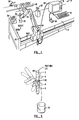
- Fig. 2 is a simplified schematic view of a sequence of positions of a portion of the robot instructed by the control system of Fig. 1 to get a robot tool to illustrate the preferred embodiment of the invention.
- Fig. 3 is a simplified perspective view of a sequence of positions of a portion of a robot rotating a test tube in a pouring motion to illustrate the preferred embodiment of the invention.
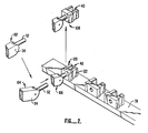
- Fig. 4 is a simplified perspective view of a sequence of positions of a portion of the robot for placing a test tube on a balance to illustrate the preferred embodiment of the invention.
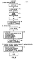
- Fig. 5 is a flow chart illustrating the steps for defining and editing robot motion and for parsing and editing procedure statements to illustrate the preferred embodiment of the invention.
- Fig. 6 is a flow chart illustrating the steps for executing a procedure to illustrate the preferred embodiment of the invention.
- Fig. 1 is a perspective view of a robot in a laboratory workcell and a robot control system to illustrate the invention. As shown in Fig. 1
robot 10 is mounted onto a table 12.Robot 10 is controlled by acontrol system 14 comprising acontroller 16, aninput keyboard 18 and apendant 20.Controller 16 is connected torobot 10 bycable 22. - The operation of
robot 10 andcontrol system 14 is as follows.Robot 10 is first taught to perform certain motions bycontrol system 14. The teaching can be textual, that is, throughinput keyboard 18. In textual teaching, the different positions in a robot motion are gathered from object location and geometry data base or from a calculation process; such position information is then typed on thekeyboard 18 and stored incontroller 16. Alternatively, non-textualmethods using pendant 20 may be used. In non-textual teaching, the user simply moves a joystick or control knobs of some kind onpendant 20 in order to move the robot to desired locations. By pressing certain buttons of the pendant, such desired robot positions are then stored incontroller 16. Either type of teaching process is referred to below as motion definition or creation. - This invention is particularly advantageous for laboratory applications and
robot 10 of Fig. 1 is shown in a laboratory setting for moving a test tube. As shown in Fig. 1, also placed on table 12 are atest tube rack 32, abeaker 34 and abalance 36. The functioning of the robot andcontrol system 14 will be illustrated in an exemplary motion whererobot 10 picks up a test tube fromrack 32, pours the content of the test tube intobeaker 34 and then places it in a test tube rack onbalance 36. Before the motion is performedrobot 10 is also instructed to get a particular robot hand or tool from atool rack 38 where the tool is suitable for picking up a test tube. - The exemplary motion described briefly above consists of four motions: (1) getting a tool from
tool rack 38, (2) picking up a test tube fromrack 32 using the tool, (3) pour the contents in the test tube intobeaker 34 and (4) placing the test tube inbalance 36. The above four motions, as arranged in the particular order listed above, is referred to as a procedure herein. Each of the four motions may be further broken down into an ordered sequence of different positions of therobot 10.Robot 10 has anactuation point 40 shown more clearly in Figs. 2 and 3. - Motions of
robot 10 are defined bycontroller 14 by specifying the desired positions of the actuation point in reference to a Cartesian coordinate system whose origin may be conveniently chosen at a corner of the table 42. Obviously other coordinate systems may also be used for implementing the invention. The three axes of the coordinate system, as shown in Fig. 1, are base, height, and reach.Robot 10 has awrist 52 which may be rotated with respect to therobot arm 54 about twoaxes 56 and 58. Whenwrist 52 is rotated aboutaxes 56, the amount of rotation is referred to as twist below. Thus,robot 10 of Fig. 1 has five degrees of freedom and is a five-axes robot. It will be understood, however, that this invention is equally applicable to robots with a different number of degrees of freedom and axes and that such applications are also. within the scope of the invention. - The motion of getting a tool will now be illustrated in reference to Table 1 below and to Fig. 2. As shown in Table 1, the motion GET..TOOL has four positions. Each position is defined by values for the four axes base, height and reach and by the angle of rotation twist about
axis 56. For the particular application described herein, rotation ofwrist 52 about axis 58 is not necessary and is therefore not specified in the table below. The positions are further modified by other factors such as GRIP defined as the distance between fingers of the tool and by FORCE defined as the force exerted by the robot on an object in the workcell.
- As shown in Table 1 above, the coordinates base, height and reach are all specified for the four positions in the motion "GET.-TOOL". The values of the other three parameters are coordinate twist and factors GRIP and FORCE each specified only by a quotation mark. Specification of a factor by a quotation mark in the tables in this application means that the value of such factor remains unchanged from the previous position. If a quotation mark is specified for a coordinate or factor at the very first position, this means that the value of such coordinate or factor takes on the default or current value specified for the robot upon initiation of the motion. Thus, in Table 1 above, the values of twist, GRIP and FORCE take on their default values and remain unchanged throughout the motion.
- Position 1 in Table 1 above is simply the present position of the robot at
position 102 in Fig. 2. Maintaining the same base coordinate, therobot arm 54 moves downwards and extends its reach to position 104 so that it is at the appropriate height for getting a tool.Position 104 thus illustratesposition 2 in Table 1 above. The robot then proceeds to position 3 in Table 1 above by maintaining the same coordinates of base and height but extends its reach towards thetool rack 38 untilwrist 52 is connected to atool 120 wherearm 54 is atposition 106.Actuation point 40 may be defined as a point betweenfingers 122 oftool 120. Thus,position 106 in Fig. 2 illustrates position 3 of Table 1 above. Afterwrist 52 is securely connected totool 120 in a conventional manner, therobot arm 54 then moves toposition 4 in Table 1 above, orposition 108 in Fig. 2. The motion "GET.TOOL" is then completed. - The above-described motion "GET.TOOL" must be first defined using
keyboard 18 orpendant 20 before the motion can be repetitively performed byrobot 10. In defining the motion, each of the four positions is stored incontroller 16, including the coordinates of each of the four positions together with attribute - FORCE the motion is therefore completely specified by teaching and storing the three coordinates of each position together with the three attribute values. For the purpose of defining the motion, there is no difference between a coordinate and a factor such as GRIP. For this reason, factors may also be referred to as coordinates below. The attribute
- FORCE is referred to herein as position attribute, In other words, a motion is completely specified by specifying the position and the position attributes of such positions. While three position attributes are illustrated in the example, it will be understood that a different number of position attributes may be used and are within the scope of the invention.
- The functions of
control system 14 of Fig. 1 in defining a motion is illustrated in the flow chart of Fig. 5, in item I. Thus, the name of the motion is first selected (Block 150). For the motion in Table 1 above, the name selected for the motion is "GET.-TOOL". Next, default values for the various attributes such as - FORCE are set for the system (Block 152). The four positions of Table 1 are then defined using
pendant 20 or by typing in the values of the coordinates using keyboard 18 (Block 154). The coordinates and position attribute values may be edited using either the pendant or the keyboard where necessary (Block 156). The motion consisting of the sequence of positions with attributes for getting a tool may then be stored in controller 16 (Block 158) so that the named motion can be reusable. - Next,
robot 10 may be taught to pick up atest tube 160 fromrack 32 in a manner similar to the motion "GET.TOOL". If the intended use of the tool is to pick up a test tube, the tool selected in "GET.TOOL" should be a suitable gripper. - Next,
robot 10 andcontroller 16 are taught to pour the contents oftest tube 160 into abeaker 34 through motion "pour" illustrated in Table 2 below in reference to Fig. 3.
- The same steps of blocks 150-158 of Fig. 5 may be used to define the motion for "POUR". As shown in Table 2 above, the height and reach of the actuation point of the robot does not change throughout the motion. The
robot wrist 52 rotates from 0 degrees in position 1 to 120 degrees inposition 5, through intermediate positions 2-4 and angles 20 degrees, 50 degrees and 90 degrees illustrated in Table 2 and Fig. 3 in order to empty the contents of the test tube intobeaker 34. In position 6wrist 52 is rotated back to its original position. Whenwrist 52 rotates the test tube using its wrist, the mouth of the test tube would follow a circular path about theactuation point 40. If theactuation point 40 remains unchanged throughout the motion, this may cause the contents oftest tube 160 to be poured onto the table instead of intobeaker 34. For this purpose it may be desirable to change the base coordinate of the actuation point slightly as illustrated in Table 2 and Fig. 3 so that the mouth of the test tube remains above the mouth ofbeaker 34 for receiving the test tube contents. , The position attributes GRIP and FORCE do not change. The value of attribute GRIP is that set during the motion for picking up the test tube and is such thattest tube 160 will not slide out betweenfingers 122.

- The motion "PLACE.TEST.TUBE.IN.BALANCE" is illustrated in reference to Table 3 above and Fig. 4. As shown in Table 3, the base coordinate of the 6 positions in the motion do not change and are such that the gripper tool is slightly to the left of
beaker 34 for placing the test tube on thebalance 36. As in Fig. 3, the positions 1-6 are used to label the robot position in Fig. 4. Thus, position 1 in Fig. 4 marks the initial position of the motion. Then, keeping the same base and height coordinates, the robot arm moves forward extending its reach toposition 2. Next, the robot arm moves downwards to position 3 placing thetest tube 160 intorack 162 placed onbalance 36. Thenposition 4 is executed where the position of the robot arm and tool remains unchanged but its grip opens alongarrows 164 so that its grip increases to the value 100. This releases the test tube from the grip byfingers 122. The robot then moves the arm toposition 5 and is then withdrawn to position 6. It is noted that the attribute GRIP changes atposition 4. In other words, the position attribute is designed so that the test tube is released atposition 4. - The four motions necessary to accomplish the purpose of getting a robot tool, picking up a test tube, pouring the contents of the test tube into a beaker and placing the test tube in the balance have been defined. At any time after the four motions are defined and before the motions are executed, it is possible to recall the motions and edit them where necessary. This is illustrated for example in Table 4 below.

- For the purpose of illustration, the motion "PLACE.TEST,-TUBE.IN.BALANCE" is recalled. The motion that appears on a computer terminal screen may, for example, resemble Table 4 above. The present position of the actuation point is indicated and the 6 positions together with the position attributes are also listed. The motion can then be edited using function keys such as the 8 function keys listed in Table 4. Where it is desired that the
fingers 122 release the test tube atposition 5 instead of atposition 4, for example, the GRIP attribute inposition 4 can be modified to a quotation mark by pressing key 4 labeled "Don'tCare". The operation ofcontroller 14 in editing is illustrated in Fig. 5. First the motion is recalled (Block 200), and the motions are edited until it is satisfactory (Block 202). The sequence of positions with attributes is then stored (Block 204). - As mentioned above, the use of other levels of attributes other than position attributes are useful for enhancing the capability and flexibility of the system. A motion attribute is one which applies to all the positions in the motion. Thus, in reference to Tables 3 and 4 all the positions are taught relative to a frame referred to in the tables as the frame of balance.l (which is different from the frame shown in Fig. 1.). Thus, the values of base, height, reach, twist are defined in reference to the frame of reference of balance.l. Where it is desired to execute the motion in the frame of reference of a different balance, such as balance.2, it is possible to edit the motion attribute to "FRAME: balance.2" as shown in Table 4. When the motion attribute is so edited, exactly the same motion as taught can be performed in reference to
balance 2 instead of to balance.l. In such manner the motion that has been taught for placing the test tube in balance.l can be used to place the test tube in balance.2 instead by simply editing the motion attribute for FRAME. A user does not have to reteach the robot and the editing process does not involve robot movements. Hence, editing is possible while the robot is being used for other useful purposes. This eliminates the down time of the robot while editing is performed and improves the efficiency of the system. - Another type of attribute is known as axis or coordinate attributes, which refers to only a single attribute amongst the position attributes. For example, the quotation mark for position 1 for the attribute GRIP in Table 4 above indicates that the value of the attribute remains unchanged; this attribute is one of two position attributes for position 1 and is itself an axis or coordinate attribute.
- Yet another type of attribute is known as the procedure attribute which is applicable for all the motions in the procedure. A somewhat different type of modifier is the motion attribute operator which can greatly enhance the capability and flexibility of the system.
- To illustrate the invention, and in particular the functions of the various levels of attributes and of the motion attribute operator, a procedure comprising 7 procedure statements is described belowfor getting a tool, picking up a test tube and for placing it in a balance.
-
- 1 This is an example of a procedure which illustrates the use of motions and the way the motion attribute operators and procedure attributes can be used to change the path of the motion at execution time
- TOOL IS NULL sets procedure tool attribute to null tool
- GOTO.GRIPPER.STATION motion (absolute) to go to where gripper tool is
- REL GET.TOOL a generic 'GET.TOOL' motion done relative to current location
- TOOL IS GRIPPER change tool attribute to 'gripper' unless overridden, future motions will use this tool
- MOVE.TO.TEST.TUBE motion to go to a specific test tube
- REL PICK.UP.TEST.TUBE generic pick up test tube at current location, this motion is linked to a special frame that includes the test tube location and the balance.
- PLACE.TEET.TUBE.- this motion has the balance frame
- IN. BALANCE attribute if the balance is ever moved, the motion does not have to be retaught, only the frame attribute needs to be changed
- First the procedure attribute for tool is set to null so that the robot proceeds without a tool, unless this command is overridden or modified later.
Next controller 14 commands the robot to execute the motion "GO.TO.GRIPPER.STATION". The robot then proceeds to where the gripper tool is, such as atrack 38 in Fig. 1. Then the controller executes the motion statement "REL GET.TOOL". The command REL is a motion attribute operator causing the motion "GET.TOOL" to be executed at the current location of the robot.Controller 14 recalls the motion "GET.TOOL" from memory (which may be taught in a manner described above) and executes the same motion at the current location of the robot. - The next procedure statement sets a procedure attribute, changing the procedure attribute for tool to "gripper", so that motions taught with a different tool can be performed subsequently with a gripper by accounting for the differences in offsets and geometries between the gripper and the teaching tool. Next the robot is commanded to execute the absolute motion "MOVE.TO.TEST.-TUBE". The next procedure statement is another motion attribute operator "REL" for performing the motion "PICK.UP.TEST.TUBE" at the current location of the robot tool. Then the robot controller system executes the statement "PLACE.TEST.TUBE.IN.BALANCE". As illustrated above, if the balance is ever moved, the motion needs not be retaught. The user needs only to change the frame motion attribute at the editing stage., Alternatively, this can be done by changing the last statement to read" PLACE.TEST.TUBE.IN.BALANCE AT BALANCE.2", where
balance 2 refers to the new position of the balance, and where the qualifier "AT BALANCE.2" would be a motion attribute operator. - Thus, as illustrated above, the invention provides a particularly powerful method for the user. Depending on the application desired, different rules can be designed by which the different levels of attributes modify one another in different manners. Thus, in the procedure illustrated above, instead of setting a procedure attribute by the statement "TOOL IS GRIPPER", it is possible to modify each of the four subsequent statements by adding a position attribute "with gripper". If the rule for the precedence of different levels of attributes is such that a position attribute overrides a procedure attribute, the position attribute "with gripper" in the subsequent statements will override the procedure attribute "TOOL IS NULL". Hence, the four subsequent statements will then be executed compensating for the fact that the tool used is a gripper. Thus, one rule for the precedence of different levels of attributes useful for some applications will be as follows (in descending order):


- In the rule above, a motion attribute operator will take precedence over all other attributes. An axis attribute will take precedence over a position, procedure or motion attribute. A position attribute will take precedence over procedure and motion attributes, and a procedure motion attribute will take precedence over a motion attribute at definition. Another useful rule is similar to the one above but with the procedure motion attributes and motion attributes at definition interchanged in position in the hierarchy.
- Another precedence rule which may be useful is as follows (in descending order):

- The above precedence rules may be particularly useful where a procedure calls for the use of different tools in different motions. For example, a motion "MOVE" may have four positions. The motion tool attribute is "small gripper". The first two positions do not indicate a tool attribute so that the motion tool attribute applies. In other words the first two positions will be executed using a small gripper. The last two positions have position tool attributes of "NULL TOOL^. According to the above rule, a position tool attribute takes precedence over a motion tool attribute, so that the last two positions will be executed without a tool.
- The execution of a procedure is illustrated by the flow charts of Figs. 5 and 6. First, a procedure is created or edited to combine motions already taught, to set procedure attributes and apply attribute operators (block 212). Thus, a set of procedure statements is created such as those discussed above for getting a gripper, picking _up a test tube, and placing the test tube in the balance. As illustrated by the above example, motion attribute operators operating on a motion such as "REL" is applied in a procedure statement. Procedure attributes such as "TOOL IS NULL" is set as well as other procedure statements. The procedure statements are then stored. The user is then ready to execute the procedure.
- In execution, the user first parses and executes the user procedure statements stored (block 214).
Controller 16 checks to see if a procedure statement contains a motion name (diamond 216). Procedure statements may contain statements other than those commanding motions, such as calculations and other useful operations. If the particular procedure statement contains no motion name, the controller checks to see if there is another procedure statement than needs to be parsed and executed (diamond 218). If no procedure statement remains to be parsed and executed, the system exits. If there is still a procedure statement that needs to be executed the system then checks the next procedure statement to see if it contains a motion name. - If the statement checked in
diamond 216 does contain a motion name, the statement is parsed for attribute operators and motion name (block 220). The motion parameters are then recalled from a file or memory (block 222). The precedence rules for all attributes in the system are then applied to compute the coordinate values for each position in the motion. The robot is then moved according to the coordinate values (block 224). After all the positions in a motion have been executed,controller 16 returns to check if there is still another procedure statement that needs to be parsed and executed (diamond 218). - In addition to the motion attribute-operators discussed above, the following are other motion attribute operators which may be useful for controlling robot motion.
-
- The following are typical and representative:
- Tool: Will cause the motion to be executed so that the specified tool tip traces the same path as the tool tip that was used in defining the motion.
- Frame: Will cause the motion to be executed relative to the specified frame rather than the frame that was used in defining the motion.
- Relative: A relative operator will cause the motion to be executed relative to the current robot position.
- Force: Will cause the specified axis (or all axes) to move until a specified force is being applied. Used as a position or motion attribute it specifies the force to be exerted along the trajectory defined by the previous and next position in the motion.
- Velocity: Will cause the motion to be executed at the specified velocity. As an axis attribute only the specified axis is moved at that velocity.
- Acceleration: Will cause the motion to be executed with the specified accelerations. between positions
- "No-Change": Will allow the motion to be executed with whatever values the specified axes currently have. (A similar "change" operator could also be defined.)
- "Move-thru": When applied to a position in a motion, the robot will move through or near the specified point without stopping.
- "Elbow": For articulated robot arms, this attribute specifies the state of the robot arm to be with either "elbow up" or "elbow down"
- "Reverse": When applied as a motion operator, the positions in the motion are to be executed in the reverse order from which the motion was defined.
- The above description of method and system is merely illustrative thereof and various changes in the steps, and other details thereof may be within the scope of the appended claims.
Claims (15)
Applications Claiming Priority (2)
| Application Number | Priority Date | Filing Date | Title |
|---|---|---|---|
| US83761486A | 1986-03-07 | 1986-03-07 | |
| US837614 | 1986-03-07 |
Publications (3)
| Publication Number | Publication Date |
|---|---|
| EP0240733A2 true EP0240733A2 (en) | 1987-10-14 |
| EP0240733A3 EP0240733A3 (en) | 1989-07-19 |
| EP0240733B1 EP0240733B1 (en) | 1994-01-12 |
Family
ID=25274962
Family Applications (1)
| Application Number | Title | Priority Date | Filing Date |
|---|---|---|---|
| EP19870103172 Expired - Lifetime EP0240733B1 (en) | 1986-03-07 | 1987-03-06 | Method and controller for controlling a mechanical manipulator |
Country Status (3)
| Country | Link |
|---|---|
| EP (1) | EP0240733B1 (en) |
| JP (1) | JPS62208103A (en) |
| DE (1) | DE3788741T2 (en) |
Cited By (5)
| Publication number | Priority date | Publication date | Assignee | Title |
|---|---|---|---|---|
| WO1990002983A1 (en) * | 1988-09-02 | 1990-03-22 | Valiant Technology Limited | A programmable robot device |
| US6435582B1 (en) | 2000-07-31 | 2002-08-20 | Motoman, Inc. | Object manipulator and manipulation system |
| US6884433B2 (en) | 1998-03-26 | 2005-04-26 | Fujisawa Pharmaceutical Co., Ltd. | Sustained release formulation containing tacrolimus |
| RU188585U1 (en) * | 2018-06-25 | 2019-04-17 | Федеральное государственное бюджетное образовательное учреждение высшего образования "ОРЛОВСКИЙ ГОСУДАРСТВЕННЫЙ УНИВЕРСИТЕТ имени И.С. ТУРГЕНЕВА" (ОГУ им. И.С. Тургенева) | MANIPULATOR |
| IT202200002300A1 (en) * | 2022-02-08 | 2023-08-08 | Idea Prototipi Srl | PROCEDURE FOR MANAGING A COLLABORATIVE WORKCELL |
Families Citing this family (1)
| Publication number | Priority date | Publication date | Assignee | Title |
|---|---|---|---|---|
| JP6594024B2 (en) * | 2015-05-07 | 2019-10-23 | ヤマト科学株式会社 | Sample processing system |
Family Cites Families (3)
| Publication number | Priority date | Publication date | Assignee | Title |
|---|---|---|---|---|
| FR2510778A1 (en) * | 1981-08-03 | 1983-02-04 | Inro France Sarl | Programmable control system for sequential robot - has keyboard with keys forming work flow diagram where keys represent volume of work, cooperating with microprocessor and memory |
| JPS5850006A (en) * | 1981-08-31 | 1983-03-24 | Fanuc Ltd | Instructing method |
| JPS58155101A (en) * | 1982-03-11 | 1983-09-14 | Yamazaki Mazak Corp | Tool selection control in four-axis numerical control lathe |
-
1987
- 1987-02-27 JP JP4504787A patent/JPS62208103A/en active Pending
- 1987-03-06 EP EP19870103172 patent/EP0240733B1/en not_active Expired - Lifetime
- 1987-03-06 DE DE19873788741 patent/DE3788741T2/en not_active Expired - Fee Related
Cited By (6)
| Publication number | Priority date | Publication date | Assignee | Title |
|---|---|---|---|---|
| WO1990002983A1 (en) * | 1988-09-02 | 1990-03-22 | Valiant Technology Limited | A programmable robot device |
| US6884433B2 (en) | 1998-03-26 | 2005-04-26 | Fujisawa Pharmaceutical Co., Ltd. | Sustained release formulation containing tacrolimus |
| US8551522B2 (en) | 1998-03-26 | 2013-10-08 | Astellas Pharma Inc. | Sustained-release formulation |
| US6435582B1 (en) | 2000-07-31 | 2002-08-20 | Motoman, Inc. | Object manipulator and manipulation system |
| RU188585U1 (en) * | 2018-06-25 | 2019-04-17 | Федеральное государственное бюджетное образовательное учреждение высшего образования "ОРЛОВСКИЙ ГОСУДАРСТВЕННЫЙ УНИВЕРСИТЕТ имени И.С. ТУРГЕНЕВА" (ОГУ им. И.С. Тургенева) | MANIPULATOR |
| IT202200002300A1 (en) * | 2022-02-08 | 2023-08-08 | Idea Prototipi Srl | PROCEDURE FOR MANAGING A COLLABORATIVE WORKCELL |
Also Published As
| Publication number | Publication date |
|---|---|
| DE3788741T2 (en) | 1994-08-04 |
| EP0240733B1 (en) | 1994-01-12 |
| JPS62208103A (en) | 1987-09-12 |
| DE3788741D1 (en) | 1994-02-24 |
| EP0240733A3 (en) | 1989-07-19 |
Similar Documents
| Publication | Publication Date | Title |
|---|---|---|
| US4843566A (en) | Robot motion control system | |
| US5511147A (en) | Graphical interface for robot | |
| US5231693A (en) | Telerobot control system | |
| Sugano et al. | WABOT-2: Autonomous robot with dexterous finger-arm--Finger-arm coordination control in keyboard performance | |
| CN110315533B (en) | Control devices, robots and robotic systems | |
| CN101092031A (en) | Off line programming tool for industrial robot | |
| Bolano et al. | Virtual reality for offline programming of robotic applications with online teaching methods | |
| JP7022260B1 (en) | Numerical control system | |
| Shimano et al. | VAL-II: A new robot control system for automatic manufacturing | |
| EP2666064B1 (en) | Method for teaching a robot movement | |
| EP0240733B1 (en) | Method and controller for controlling a mechanical manipulator | |
| Salihović et al. | RoboDK to MATLAB Joint Position Transformation | |
| JPH0699376A (en) | Method and system for teaching robot trajectories | |
| Nguyen et al. | Automated inverse kinematics configuration selection for path planning of a 6-DOF Robot | |
| JPH06134684A (en) | Teaching method of robot track | |
| JPH0699377A (en) | Method for teaching robot track | |
| Matour et al. | Intuitive robot path planning through augmented reality | |
| CN115735166A (en) | Numerical control system | |
| Vertut et al. | Sensor-aided and/or computer-aided bilateral teleoperator system (SCATS) | |
| Mabong et al. | Robot Manipulator Programming Via Demonstrative-Kinesthetic Teaching for Efficient Industrial Material Handling Applications | |
| Crane III et al. | Off-line programming and path generation for robot manipulators | |
| JPH07205068A (en) | Robot coordinate system setting method | |
| Glagowski et al. | Human factors in robot teach programming | |
| Ranky | Programming industrial robots in FMS (A survey with particular reference to off-line, high-level robot program generation using VAL, VAL-II, AML And MARTI) | |
| Nakamura et al. | Controller for industrial robots |
Legal Events
| Date | Code | Title | Description |
|---|---|---|---|
| PUAI | Public reference made under article 153(3) epc to a published international application that has entered the european phase |
Free format text: ORIGINAL CODE: 0009012 |
|
| AK | Designated contracting states |
Kind code of ref document: A2 Designated state(s): CH DE FR LI |
|
| PUAL | Search report despatched |
Free format text: ORIGINAL CODE: 0009013 |
|
| AK | Designated contracting states |
Kind code of ref document: A3 Designated state(s): CH DE FR LI |
|
| 17P | Request for examination filed |
Effective date: 19891219 |
|
| 17Q | First examination report despatched |
Effective date: 19911223 |
|
| GRAA | (expected) grant |
Free format text: ORIGINAL CODE: 0009210 |
|
| AK | Designated contracting states |
Kind code of ref document: B1 Designated state(s): CH DE FR LI |
|
| REF | Corresponds to: |
Ref document number: 3788741 Country of ref document: DE Date of ref document: 19940224 |
|
| ET | Fr: translation filed | ||
| PLBE | No opposition filed within time limit |
Free format text: ORIGINAL CODE: 0009261 |
|
| STAA | Information on the status of an ep patent application or granted ep patent |
Free format text: STATUS: NO OPPOSITION FILED WITHIN TIME LIMIT |
|
| 26N | No opposition filed | ||
| PGFP | Annual fee paid to national office [announced via postgrant information from national office to epo] |
Ref country code: FR Payment date: 19950210 Year of fee payment: 9 Ref country code: CH Payment date: 19950210 Year of fee payment: 9 |
|
| PGFP | Annual fee paid to national office [announced via postgrant information from national office to epo] |
Ref country code: DE Payment date: 19950227 Year of fee payment: 9 |
|
| PG25 | Lapsed in a contracting state [announced via postgrant information from national office to epo] |
Ref country code: LI Effective date: 19960331 Ref country code: CH Effective date: 19960331 |
|
| REG | Reference to a national code |
Ref country code: CH Ref legal event code: PL |
|
| PG25 | Lapsed in a contracting state [announced via postgrant information from national office to epo] |
Ref country code: FR Effective date: 19961129 |
|
| PG25 | Lapsed in a contracting state [announced via postgrant information from national office to epo] |
Ref country code: DE Effective date: 19961203 |
|
| REG | Reference to a national code |
Ref country code: FR Ref legal event code: ST |