EP0240599A2 - Dispositif pour déterminer les forces de contact entre une monture de lunettes et la tête d'un porteur de lunettes - Google Patents
Dispositif pour déterminer les forces de contact entre une monture de lunettes et la tête d'un porteur de lunettes Download PDFInfo
- Publication number
- EP0240599A2 EP0240599A2 EP86114883A EP86114883A EP0240599A2 EP 0240599 A2 EP0240599 A2 EP 0240599A2 EP 86114883 A EP86114883 A EP 86114883A EP 86114883 A EP86114883 A EP 86114883A EP 0240599 A2 EP0240599 A2 EP 0240599A2
- Authority
- EP
- European Patent Office
- Prior art keywords
- sensor
- head
- measuring
- force
- tip
- Prior art date
- Legal status (The legal status is an assumption and is not a legal conclusion. Google has not performed a legal analysis and makes no representation as to the accuracy of the status listed.)
- Withdrawn
Links
Images


Classifications
-
- G—PHYSICS
- G01—MEASURING; TESTING
- G01L—MEASURING FORCE, STRESS, TORQUE, WORK, MECHANICAL POWER, MECHANICAL EFFICIENCY, OR FLUID PRESSURE
- G01L5/00—Apparatus for, or methods of, measuring force, work, mechanical power, or torque, specially adapted for specific purposes
Definitions
- the invention relates to a device according to the preamble of patent claim 1.
- the glasses frame touches the head of the glasses wearer in several places, for example in the area of the nose flanks, the nose root and the ears. As soon as a pressure is exerted at one of these contact points that exceeds a threshold value that varies from one wearer to another, complications can occur when wearing the glasses, which considerably impair the well-being of the wearer.
- the invention has for its object to provide a device with which the fit of a spectacle frame on the head of the spectacle wearer can be precisely controlled.
- the device according to the invention creates a force measuring probe in the form of the force sensor, which is designed such that it can be brought to the contact points between the spectacle frame and the head of the spectacle wearer. This can be done, for example, by placing the individual force sensors on the respective contact surfaces with the holder removed and then fitting the holder. Another way of using the invention
- the device consists of inserting a force sensor or several force sensors between the frame and the head of the spectacle wearer and then bringing the frame back into the correct position. With such a device, the forces occurring when the spectacle frame is worn can be precisely determined individually.
- the development according to claim 2 creates a simple measuring device, which, in the form of a simple measuring probe, represents a handy tool for the ophthalmologist or optician to check the fit of the spectacle frame.
- a relatively large scope remains for the design of the force sensor.
- a flap-like structure can be used that clings to the contact surfaces in several directions.
- a particularly simple and yet sufficiently precise design of the force sensor is the subject of claim 4.
- This measuring contact surface can be defined not only in terms of position but also in size in order to thereby define the measuring point precisely and reproducibly and to obtain information about the pressure load.
- the contact surfaces between the eyeglass frame and the head of the eyeglass wearer are not only arranged differently in terms of space, but also have different geometries. For example, there are almost flat contact surfaces in the area of the nose flanks, whereas in the area of the nose root and in the area of the ear attachment on the skull there is a pairing between two surfaces, each of which is curved in two planes.
- the mechanical part of the pressure sensor is preferably formed by a pair of probes which act as displacement transducers in the area of the measuring point to be assessed. In this way, the length that is anyway required to form a fine and possibly narrow tip on the pressure sensor can be used to provide a suitable path and / or force ratio, which is then used as an input variable for the electrical working signal transducer can be used.
- the design according to claim 11 is of particular advantage, since in this way the defined bending point can be optimized independently of the design of the tongues.
- Another advantage of this embodiment is that the measured value signal converter can be attached at a location which is at a relatively great distance from the actual measuring point, so that it is largely protected from external influences.
- the senor is designed according to claim 13, there is a simple and robust construction.
- the probe tongue which is firmly connected to the probe head and the element equipped with the bending point, is not to be used as a displacement transducer element in this embodiment, so that measurement errors can occur in the case of extremely small forces to be measured, in that the probe with this fixed probe tongue also force of different magnitude is pressed onto the contact surface.
- the development according to claim 14 is able to eliminate such measurement errors.
- the outer surface of the movable probe tongue is convex or convex, so that the sensor can be easily pushed between the spectacle frame and the head of the spectacle wearer, without thereby damaging the measuring probe tongue.
- a piezo element can also be used which emits a voltage which is essentially proportional to the force acting thereon.
- This piezo element is attached essentially at the same point as the element equipped with the desired bending point according to the development according to claim 11 ff.
- the development according to claim 17 is particularly advantageous in this variant.
- This variant has the advantage that the probe tip can be made more stable in the form of a closed hollow profile.
- a large free space is also opened with regard to the design of the probe tip, so that all contact points between the spectacle frame and the head of the spectacle wearer can be optimally checked by a suitable choice of the probe tip.
- the plastic bladder itself can be removed from the sensor head Define the measuring point in the preceding section.
- this section of the plastic bubble to carry a separate element which serves to form the defined measuring point, which can optionally be provided with a predetermined area.
- the measuring accuracy of the device can be increased.
- the tip of the sensor head can be placed in a controlled manner in the area of the contact surface by continuously monitoring the contact pressure applied by the doctor or the optician.
- the force sensor can also work purely according to the piezoelectric principle. In this case, the same advantages result with regard to the design of the sensor head as have been described above in connection with the pneumatic displacement transducer.
- This measuring method has the advantage that the piezo crystal element is not noticeably or visibly deformed under the action of force.
- the thickness of the probe tip can be reduced in this way in relation to the solution variants described above by the maximum displacement measurement.
- the use of the piezoelectric effect in force measurement also has the advantage that the piezo element can be fixed relatively easily in the tip of the sensor head since there are no noticeable ones Deformations of the transducer must be taken into account.
- simple measures must be taken to ensure that the piezo crystal protrudes both from one side of the sensor head facing the spectacle frame and from the other side facing the head surface.
- the physician or optician handling the device according to the invention can reliably check when attaching the pressure measuring probe whether he unintentionally leads the measuring sensor to the measuring point with an excessive pressing force.
- a force or displacement transducer is accommodated in a sensor head which is designed like a housing.
- a joint with preferably several degrees of freedom is incorporated between the sensor head and the holder or holder , so that the force or displacement transducer can align with its direction of sensitization normally to the respective contact surfaces.
- the force sensor is only sensitized to a force on a very specific and size-defined area, so that the measuring point can be reproducibly defined and the measured force can be converted into a pressure variable.
- Such a sandwich film can be made extremely thin even with the integration of the signal transmitter mentioned in claim 27, so that the fit of the glasses is not noticeably influenced by the introduction of the film at a contact point between the frame and the head of the glasses wearer.
- the measuring point can be determined even more precisely and the load profile can be determined more precisely over certain larger contact distances.
- the intermediate layer is advantageously formed by a soft plastic insert can be compressed under load.
- a soft plastic insert can be compressed under load.
- the seat of an eyeglass frame can be checked with the aid of a single probe, which is sequentially introduced to the different contact areas between the eyeglass frame and the head of the eyeglass wearer, the individual measured values either being entered in a log or in be stored in a memory.
- the entire contact area between the lug and nose can be checked for optimal fit at the same time. Due to the alignability of the sensor heads, a rough adjustment can already be carried out in order to preclude the above-mentioned constraining forces from the outset in the event of an automatic feed of the collecting holder which may be provided.
- the development of the device according to claim 36 is particularly advantageous. All the load values measured one after the other are to be made visible in the context of the display device, so that the doctor or optician can be given a superordinate overall picture of the seat of the spectacle frame despite selective measurements.
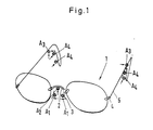
- reference numeral 1 denotes an eyeglass frame which has a bridge 2, two webs 3, two jaws 4 and two brackets 5.
- the black dots A schematically indicate the contact areas between the spectacle frame 1 and the head of the spectacle wearer (not shown) which are decisive for the comfort of the spectacles.
- A1 the contact areas in the area of the nose flanks
- A2 the contact area in the area of the nasal saddle
- A3 the contact areas between the bracket 5 and the upper area of the ear attachment and with A4 those contact points designated, which are behind the ear in the so-called burr of the ear attachment are located.
- the contact forces in the area of the contact surfaces A are held in such a way that the force distribution is somewhat symmetrical, i.e. no contact force peaks occur on any contact surface.
- the device to be described in more detail below with reference to FIGS. 2 to 25 is used to check the exact fit of the glasses, with which the forces in the area of the contact surfaces between the glasses frame 1 and the head of the glasses wearer can be measured precisely and reproducibly.
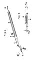
- the device shown in Fig. 3 represents a measuring probe 8, which consists essentially of three parts.
- a pen-like holder 10 carries at its front end a pressure or force sensor 12 which is plate-shaped or sheet-shaped at least in the area of the tip, so that it can be arranged with its sensor tip 14 on the respective contact surfaces A, without this to change something at the seat of the eyeglass frame, that is to say in the spatial allocation between the eyeglass frame and the head of the glasses wearer.
- the probe tip 14 is made extremely flat, which can be seen, for example, from the sectional view according to FIG. 3.
- the height H14 is approximately in the order of 0.6 to 0.8 mm, so that, for example, by inserting the probe 12 under the glasses frame noticeable impairment of the support conditions on the other contact surfaces is caused.
- the sensor tip 14 of the embodiment according to FIG. 2 is designed in the manner of a tongue in order to be able to use the sensor to reach all the decisive contact areas A between the spectacle frame and the head of the spectacle wearer.
- the components of the sensor tip are rounded, so that the sensor tip cannot tilt or get caught.
- the third part of the measuring probe 8 is formed by a signal converter with associated signal processing device, of which only the electrical connections 16 can be seen in FIG. 2.
- the signal converter is used to convert a signal corresponding to the force in the contact area A into an electrical signal, which - as will be explained in more detail later - is then processed in a suitable manner.
- This conversion takes place in the embodiment according to FIGS. 2 and 3 in that a path proportional to the force is tapped off directly and this path is then possibly converted into an electrical signal proportional to it via a translation.
- the maximum measuring path is designated in Fig. 3 with W M , which is of the order of 0.1 mm.
- W M which is of the order of 0.1 mm.
- the structure of such a force sensor will be explained in detail later with reference to FIGS. 9 ff.
- the measurement is not limited to this electromechanical principle. Rather, it is possible to operate the force sensor 12 on the basis of further physical effects, which will be explained below using the embodiments according to FIGS. 4 to 8.
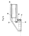
- the holder 22 carries a probe head 28 in the form of a hollow housing which has a rear portion 30 and a tip portion 32 which is essentially dimensioned as the probe tip according to FIGS. 2 and 3.
- a recess 34 with a preferably precisely defined geometry is provided through the sensor, through which the recess 34 extends to fill a plastic bubble 36 which is filled with compressed gas and is connected to a pressure sensor 38. Automatic pressure regulation in the plastic bladder takes place via a pressure line 40.
- the measuring probe 20 functions in such a way that the pressure difference which arises when the bladder 36 is loaded by the measuring force F M is measured in the gas pressure sensor 38, converted there into an electrical signal and finally evaluated electrically.
- a further recess for the plastic bladder 36 can also be provided on the side of the sensor head 28 facing the contact surface A, so that only the normal forces which are supported by the support of the Spectacle frame 42 are caused.
- a more or less large initial pressing force with which the probe head 28 is pressed against the surface of the body 42 by the operator of the measuring probe can no longer falsify the measurement result . This is particularly important because the forces to be measured range from 1 to 100 mN.
- 5 is designated by 50 and in turn has a holder 52 which can be designed as a handle.
- a sensor head 54 is provided, which is somewhat simplified compared to the embodiments described above.
- the sensor head 54 carries a foil-like measuring tongue 56, which can be designed as a flexible measuring flap, which can nestle against the contact surface A between the body 42 and the spectacle frame (not shown).
- a defined elevation 58 is provided in the front area of the measuring tongue 56, which preferably has a defined area of predetermined area.
- signal converters are provided in the form of pairs of coils, capacitor plates or Hall elements, which are integrated into an electrical circuit in such a way that when the distance between the signal converters is changed, the corresponding signal is generated. This will be explained in more detail below using a capacitive signal converter. 6 and 7, this signal converter has two capacitor plates 60 and 62 which are at a distance A U from one another when the measuring tongue 56 is not loaded. The capacitor plates are each embedded in an edge layer 64 or 66, in which the power supply for the capacitor plates is also provided. Between the edge layers 64 and 66, an intermediate layer 68 is provided, which consists of soft plastic, which is under load can squeeze.
- the measuring force F M acts on the measuring tongue in the area of the capacitor plates 60 and 62, the distance between the capacitor plates decreases, whereby the circuit in which the capacitor plates are integrated generates a signal corresponding to the force, which is finally evaluated.
- a measuring probe works in the same way if coil elements or Hall elements are used instead of the capacitor plates.
- the particular advantage of this embodiment is that the measuring tongue 56 can be inserted in the contact surface area A without force due to the flexural softness of the film, so that no manipulation of the measuring result can be caused by the handling of the measuring probe 50.
- FIG. 8 Another embodiment of the device is shown in FIG. 8.
- This measuring probe is identified by reference numeral 70, and it works on the principle of the piezo effect.
- a holder 71 carries a sensor head 72 substantially corresponding to the sensor head according to FIG. 4, in the tip section 74 of which a piezo element 76 is arranged, which is connected via a line 78 and a connecting cable 80 to an evaluation circuit (not shown).
- the piezo element 76 extends through an unspecified recess in the tip section 74, so that it is preferably loaded by the measuring force F M on a defined measuring surface.
- the mechanical loading of the piezo element 76 generates a voltage that follows the loading according to a certain law, which can then be amplified and evaluated.
- the core of the force sensor 12 forms a pair of measuring tongues 82 and 84, which are shown in detail in FIGS. 12 and 13.
- the measuring tongues 82 and 84 extend substantially parallel to one another away from a sensor head housing 86 parallel to the axis of the holder 10. Both measuring tongues are angular and are in firm contact with legs 92 and 94 of legs 92 and 94 of a signal converter - Elements 96, shown in detail in FIG. Fixing screws 98 and 100 are provided for this purpose.
- the legs 92 and 94 are bridged by a yoke-like web 102, which functions as a defined bending point.
- the yoke-shaped web 102 carries a strain gauge 104, which is shown in FIGS. 10 and 11.
- the strain gauge can either be glued or vapor-deposited, and it is connected to an electrical evaluation circuit via electrical lines 106.
- the upper measuring tongue 84 has a projecting surface 108 in the region of its projecting end which is to be brought into contact with the corresponding section of the spectacle frame. Since the thickness of the measuring tongue 84 is only in the range between 0.2 and 0.5 mm, the lower measuring tongue 82 forms a border for the upper measuring tongue 84, as can be seen more clearly from FIG. 13. For this purpose, the lower measuring tongue 82 has a recess 110 , which is adapted to the contour of the upper measuring tongue 84, so that the latter is protected from uncontrolled loads by a bordering web running around the measuring tongue 84.
- FIGS. 12 and 13 The attachment of the assembly unit shown in FIGS. 12 and 13, consisting of measuring tongues 82 and 84 and signal-shaping element 96, to the sensor head housing 86 is shown in detail in FIG. 14. This unit is shown here with dash-dotted lines.
- a pair of screws 114 and 116, indicated schematically, and a pair of screws 118 firmly clamp the angular section 88 in the rear lower part of the housing 86, which is equipped with a receiving opening 120 for functional engagement with the holder 10.
- the measuring probe 8 shown in FIGS. 9 to 14 exactly reproduces the contact forces between the spectacle frame and the body 42 of the spectacle wearer when the housing 86 of the probe head is free of those forces is held, which are applied to the contact surface A via the holder handle.
- an articulated device with several degrees of freedom of rotation is advantageously interposed between the holder and the sensor head housing.
- An embodiment of such a joint device is shown in FIGS. 15 and 16. It comprises a first swivel joint 122 and a second swivel joint 124.
- the first swivel joint 122 has an articulation axis 126 which is perpendicular to the vertical plane of symmetry 128 of the measuring probe.
- the hinge axis 130 of the second swivel joint 124 coincides with the axis of the holder 10.
- the holder has a guide bore 132 into which an intermediate joint element 134 engages. The end of this intermediate element 134 facing away from the bore 132 forms the first half 136 of the first swivel joint 122 designed as a hinge.
- the second half 138 of the hinge is formed by one end of a connecting pin 140 of the housing 86.
- the hinge is stabilized by a spiral spring 142. This rotational movement of the pivot joint 124 is limited by a stop and guide pin 144 which can slide in a link 146 of a guide projection 148 of the holder 10.
- the articulation devices 122 and 124 are covered by a bellows 150 in order to protect the moving parts from external influences.
- the holder 10 can be moved manually almost free of any constraining forces to any point on the contact surfaces A to be examined, the tip of the sensor nestling well against the ground.
- an additional Means are provided, which itself ensures during the measuring process that the spring stabilization of the joint 122 is disabled under its unlocking.
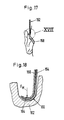
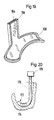
- Measuring probes have been described above which have a flat contact surface on at least one side. Due to the tongue-shaped design, this shape is itself suitable for measuring contact forces in multi-curved surface areas. 17 to 20 show further exemplary embodiments of sensors which are particularly suitable for measuring the contact forces on complexly curved contact surfaces. 17, reference numeral 152 denotes a probe tip, which in turn has two measuring tongues 154 and 156 for the electromechanical signal conversion. The sensor tip 152 is designed such that it is particularly suitable for measuring the contact forces between the spectacle frame and the head of the spectacle wearer in the region 158 of the ear attachment on the skull of the spectacle wearer.
- the outer ends of the measuring tongues 154 and 156 are bent, so that they conform to the shape of the groove 160 of the ear 162.
- the movable measuring tongue 156 again has an elevation 164 at which the measuring force F M is to be introduced. It can be seen from the illustration that when this measuring force is introduced, there is a relative shift between the measuring tongues 154 and 156, which can then be converted into an electrical signal corresponding to the force by means of a signal shaping element.
- the measuring tongues are designated by the reference numerals 164 and 166.
- the tip section of the measuring tongue 164 is thus given the shape of a partial toroidal surface, with this configuration also making it possible to surround the movable measuring tongue 166 with a border web 168.
- the configuration of the probe tip according to FIGS. 17 to 19 is also possible for all those cases in which no measuring tongues movable relative to one another are used, but in which a housing of the probe head continues into the tip region of the probe.
- the reference number 170 generally designates a sensor head which bears a tip 172 which is adapted to the surface design of the head section on which the measurement of the spectacle seat is to be carried out.
- a force transducer 174 for example in the form of a piezo element or a plastic bladder, is arranged in this tip section 172 and is coupled to a signal converter 176 via a connecting line (not shown).
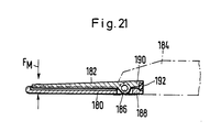
- a further embodiment of a force sensor is shown schematically, in which the Um conversion of the input variable in turn takes place electromechanically into an output signal assigned to the measuring force F M.
- two measuring tongues 180 and 182 are again provided, which act as displacement transducers.
- both measuring tongues 180 and 182 are movably mounted in a sensor head 184.
- a common axis 186 is provided, around which the measuring tongues 180 and 182 can be pivoted.
- Each measuring tongue is designed as a two-armed lever.
- the lever sections 188 and 190 opposite the projecting end are fixedly coupled to a signal-forming element 192 which is put under tension when the measuring tongues 180, 182 are loaded by the measuring force F M.
- the signal shaping element 192 can in turn carry a strain gauge or be designed as a piezo element.
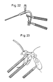
- This measuring probe designated by reference number 200, is designed as a multiple measuring probe.
- a multiple measuring head 206 On a carrier 202, which can sit on a movable carriage 204, a multiple measuring head 206 is mounted, which carries a plurality of pressure sensors 208 to 212, which are identical to the pressure or force sensors described above forms can be.
- the force sensors 208 to 212 are preferably connected via joints 214 to 218 to associated sensor heads 220 to 224, which can preferably be roughly aligned with respect to the multiple measuring head 6.
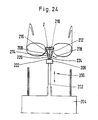
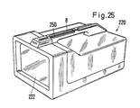
- 25 shows a measuring system consisting of the pressure measuring probe 8 and a preferably portable measuring device 220 which, in addition to the above-mentioned evaluation circuit for the signal generated by the measuring sensor, has a screen 222 with which the individual measurements can be clearly represented in their entirety.
- FIG. 26 shows components of the measuring system according to FIG. 25 on the basis of a block diagram which illustrates the signal flow of the measuring signals. It can be seen from this illustration that the measurement signal given at 230 in the device is applied to an operational amplifier 236 via a measurement amplifier 232 with the aid of an oscillator 234. A signal is processed with the aid of an A / D converter 238 for converting the analog measurement voltage into a digital signal.
- an image processing system consisting of a screen controller 240 with a character generator and a unit 242 for the timing of the vertical and horizontal synchronization signals for the screen 222.
- the image processing and the screen monitor are controlled by a Microprocessor 244, which also controls a D / A converter 246 for converting the digital measured values into the analog correction voltage for automatic zeroing.
- the measuring system thus has a control part for automatic re-calibration of the sensors during operation.
- a power supply unit 252 provides the units with a suitable operating voltage.
- Reference number 248 denotes a start logic block that triggers the signal processing. This start logic block is controlled by a button 250, which is preferably located on the holder 8, as shown in the figures.
- the probe tip can be covered with a plastic cap 75 or 85 in order to shield the sensitive parts of the probe from external influences.
- the device can also be designed such that one or more force sensors are attached as separate elements to the relevant contact points between the spectacle frame and the head of the spectacle wearer and are connected to a signal evaluation circuit via electrical connections.
- the spectacle frame is put on, after which the individual forces at the relevant contact points can be determined and called up in succession or simultaneously.
Landscapes
- Physics & Mathematics (AREA)
- General Physics & Mathematics (AREA)
- Eyeglasses (AREA)
- Force Measurement Appropriate To Specific Purposes (AREA)
Applications Claiming Priority (2)
| Application Number | Priority Date | Filing Date | Title |
|---|---|---|---|
| DE3610897 | 1986-03-24 | ||
| DE19863610897 DE3610897A1 (de) | 1986-03-24 | 1986-03-24 | Vorrichtung zur bestimmung der kraefte im bereich der kontaktflaechen zwischen einer brillenfassung und dem kopf eines brillentraegers |
Publications (2)
| Publication Number | Publication Date |
|---|---|
| EP0240599A2 true EP0240599A2 (fr) | 1987-10-14 |
| EP0240599A3 EP0240599A3 (fr) | 1989-06-14 |
Family
ID=6297673
Family Applications (1)
| Application Number | Title | Priority Date | Filing Date |
|---|---|---|---|
| EP86114883A Withdrawn EP0240599A3 (fr) | 1986-03-24 | 1986-10-27 | Dispositif pour déterminer les forces de contact entre une monture de lunettes et la tête d'un porteur de lunettes |
Country Status (4)
| Country | Link |
|---|---|
| US (1) | US4873994A (fr) |
| EP (1) | EP0240599A3 (fr) |
| JP (1) | JPH0623673B2 (fr) |
| DE (1) | DE3610897A1 (fr) |
Families Citing this family (12)
| Publication number | Priority date | Publication date | Assignee | Title |
|---|---|---|---|---|
| DE3730180A1 (de) * | 1987-09-09 | 1989-03-30 | Gutehoffnungshuette Man | Drehgestell mit gelenkten radsaetzen |
| DE8908041U1 (de) * | 1989-06-29 | 1989-08-17 | Nettelhorst, Frhr. von, Herwig, Dr.-Ing., 1000 Berlin | Sensor für von tierischen oder menschlichen Körpern ausgehende mechanische Kräfte |
| DE9001342U1 (de) * | 1990-02-06 | 1991-06-06 | Grote & Hartmann Gmbh & Co Kg, 42369 Wuppertal | Vorrichtung zur Kontaktkraftmessung |
| DE4003552C2 (de) * | 1990-02-06 | 1996-02-29 | Grote & Hartmann | Verfahren und Vorrichtung zur Kontaktkraftmessung |
| US5611147A (en) * | 1993-02-23 | 1997-03-18 | Faro Technologies, Inc. | Three dimensional coordinate measuring apparatus |
| WO2000013571A1 (fr) * | 1998-09-04 | 2000-03-16 | Sunrise Technologies International, Inc. | Appareil et procede permettant de recevoir la tete d'un sujet |
| US6941182B2 (en) * | 2002-11-26 | 2005-09-06 | Resmed Limited | Method and apparatus for measurement of pressure at a device/body interface |
| DE102013207063A1 (de) | 2013-04-19 | 2014-10-23 | Bayerische Motoren Werke Aktiengesellschaft | Verfahren zum Auswählen einer Informationsquelle aus einer Mehrzahl von Informationsquellen zur Anzeige auf einer Anzeige einer Datenbrille |
| DE102013207064A1 (de) * | 2013-04-19 | 2014-10-23 | Bayerische Motoren Werke Aktiengesellschaft | Verfahren zur Auswahl einer Informationsquelle zur Anzeige auf einer Datenbrille |
| CN104764574A (zh) * | 2015-04-01 | 2015-07-08 | 无锡市康明医疗器械有限公司 | 一种眼镜架部件与鼻梁镜托弹性测定仪 |
| EP3278174B1 (fr) | 2015-04-02 | 2023-06-07 | Essilor International | Système de surveillance de la position d'un dispositif monté sur la tête |
| WO2016176630A1 (fr) * | 2015-04-30 | 2016-11-03 | Oakley, Inc. | Dispositifs pouvant être portés tels que des lunettes personnalisées dotées de paramètres de porteur individuels |
Family Cites Families (15)
| Publication number | Priority date | Publication date | Assignee | Title |
|---|---|---|---|---|
| US3031152A (en) * | 1958-04-28 | 1962-04-24 | Dusenbery Co John | Improved apparatus for measuring, indicating, and controlling web tension |
| US2935213A (en) * | 1958-12-19 | 1960-05-03 | Int Harvester Co | Fork lift vehicle weighing scale |
| US3151306A (en) * | 1961-08-25 | 1964-09-29 | Baldwin Lima Hamilton Corp | Electrical strain transducer |
| GB1138613A (en) * | 1965-03-11 | 1969-01-01 | Derek Joseph Harry Goddin | Improvements in or relating to pressure measuring devices |
| US3566679A (en) * | 1969-08-21 | 1971-03-02 | Irwing N Toftness | Linear pressure device |
| US3760637A (en) * | 1971-02-26 | 1973-09-25 | Rodel Inc | Nip pressure measurement |
| DE2162683C3 (de) * | 1971-12-17 | 1980-09-04 | Hugo Sachs Elektronik Kg, 7801 March | Einrichtung zur Messung des Weges eines Meßobjektes bei einer am Meßobjekt wirkenden Kraft |
| DE2414569C2 (de) * | 1974-03-26 | 1975-10-23 | Siemens Ag, 1000 Berlin Und 8000 Muenchen | KraftmeBgerät zum Messen von kleinen Kräften, insbesondere von Kontaktfederkräften sowie Verfahren zur Herstellung eines derartigen Gerätes |
| US4047584A (en) * | 1976-07-08 | 1977-09-13 | Daly Richard T | Bee-hive scale |
| US4167869A (en) * | 1977-10-07 | 1979-09-18 | The Gillette Company | Apparatus for measuring hair grooming force |
| US4380171A (en) * | 1980-12-29 | 1983-04-19 | Amp Incorporated | Method and apparatus for measuring normal contact forces in electrical connector |
| US4426884A (en) * | 1982-02-01 | 1984-01-24 | The Langer Biomechanics Group, Inc. | Flexible force sensor |
| US4503705A (en) * | 1982-02-24 | 1985-03-12 | The Langer Biomechanics Group, Inc. | Flexible force sensor |
| GB8313834D0 (en) * | 1983-05-19 | 1983-06-22 | Trw Probe Electronics Co Ltd | Strain transducers |
| US4667512A (en) * | 1986-03-17 | 1987-05-26 | Amp Incorporated | Normal force transducer for receptacle contact |
-
1986
- 1986-03-24 DE DE19863610897 patent/DE3610897A1/de active Granted
- 1986-10-27 EP EP86114883A patent/EP0240599A3/fr not_active Withdrawn
-
1987
- 1987-03-23 JP JP62068743A patent/JPH0623673B2/ja not_active Expired - Lifetime
-
1989
- 1989-01-26 US US07/303,005 patent/US4873994A/en not_active Expired - Fee Related
Also Published As
| Publication number | Publication date |
|---|---|
| EP0240599A3 (fr) | 1989-06-14 |
| JPH0623673B2 (ja) | 1994-03-30 |
| DE3610897C2 (fr) | 1991-06-13 |
| DE3610897A1 (de) | 1987-10-08 |
| JPS62235534A (ja) | 1987-10-15 |
| US4873994A (en) | 1989-10-17 |
Similar Documents
| Publication | Publication Date | Title |
|---|---|---|
| EP1688727B1 (fr) | Dispositif dynamométrique et élément d'extensomètre | |
| DE3881754T2 (de) | Gerät zur Anzeige von Pulswellen. | |
| EP0240599A2 (fr) | Dispositif pour déterminer les forces de contact entre une monture de lunettes et la tête d'un porteur de lunettes | |
| DE29806179U1 (de) | Crimpzange | |
| DE4001179A1 (de) | Verfahren und vorrichtung zur nichteindringenden druckmessung | |
| EP2099383B1 (fr) | Procédé et dispositif de transfert, par rapport à un axe d'articulation, d'un modèle de mâchoire | |
| DE19947001A1 (de) | Instrument zur Messung der Oberflächenkontur | |
| EP0372247A2 (fr) | Clef dynamométrique et dispositif pour son réglage et son étalonnage | |
| EP2096424A2 (fr) | Dispositif d'actionnement destiné à vérifier des clés dynamométriques | |
| DE69715874T2 (de) | Numerischer Kraftsensor mit einer elastisch verformbaren Messzelle und Verfahren zur direkten Messung einer angewendeten Kraft | |
| WO2005010457A2 (fr) | Dispositif de mesure de rugosite comportant un etalon | |
| DE69324686T2 (de) | Vorrichtung zum positionieren des kopfes einer person in einem koordinatensystem | |
| DE2911561C2 (de) | Wandler zum Umwandeln von Druckschwankungen in elektrische Signale | |
| DE102024110271A1 (de) | Automatisches Messsystem und Steuer- bzw. Regelverfahren für ein automatisches Messsystem | |
| DE102007024479A1 (de) | Verfahren zur Dimensionierung von Zahnbrücken unter Berücksichtigung der auf ein antagonistisches Zahnpaar wirkenden Kraft sowie Apparatur zu deren Messung und Verwendung derselben | |
| DE102018110814B3 (de) | Vorrichtung und verfahren zur kalibrierung von messaufnehmern | |
| EP2015675B1 (fr) | Système d'affichage et procédé pour afficher des forces de réaction du sol sur un corps humain | |
| EP0284671B1 (fr) | Dispositif de mesure | |
| DE29501355U1 (de) | Drehmomentschlüssel | |
| DE10136559B4 (de) | Verfahren zum Diagnostizieren von Schäden in einem messenden Tastkopf eines Koordinatenmessgeräts | |
| DE102012104017A1 (de) | Messeinrichtung und Verfahren zur Messung von Kugeln | |
| EP0122678A2 (fr) | Appareil pour mesurer la position d'au moins une tête magnétique dans un magnétophone à cassette vis-à-vis de la position de défilement de la bande | |
| DE3512969C2 (fr) | ||
| DE3335743A1 (de) | Vorrichtung zur ausmessung leicht deformierbarer objekte | |
| DE4204544C2 (de) | Vorrichtung zur Lagebestimmung skelettaler Bereiche am Schädel |
Legal Events
| Date | Code | Title | Description |
|---|---|---|---|
| PUAI | Public reference made under article 153(3) epc to a published international application that has entered the european phase |
Free format text: ORIGINAL CODE: 0009012 |
|
| AK | Designated contracting states |
Kind code of ref document: A2 Designated state(s): AT BE CH DE ES FR GB GR IT LI LU NL SE |
|
| RAP1 | Party data changed (applicant data changed or rights of an application transferred) |
Owner name: EYEMETRICS-SYSTEMS AG |
|
| PUAL | Search report despatched |
Free format text: ORIGINAL CODE: 0009013 |
|
| AK | Designated contracting states |
Kind code of ref document: A3 Designated state(s): AT BE CH DE ES FR GB GR IT LI LU NL SE |
|
| 17P | Request for examination filed |
Effective date: 19890710 |
|
| 17Q | First examination report despatched |
Effective date: 19900718 |
|
| STAA | Information on the status of an ep patent application or granted ep patent |
Free format text: STATUS: THE APPLICATION IS DEEMED TO BE WITHDRAWN |
|
| 18D | Application deemed to be withdrawn |
Effective date: 19901129 |
|
| RIN1 | Information on inventor provided before grant (corrected) |
Inventor name: LEUZINGER, CHRISTOPH Inventor name: ANGER, WILHELM |