EP0240318A2 - Apparatus and method for suppression of turbine engine noise - Google Patents
Apparatus and method for suppression of turbine engine noise Download PDFInfo
- Publication number
- EP0240318A2 EP0240318A2 EP87302803A EP87302803A EP0240318A2 EP 0240318 A2 EP0240318 A2 EP 0240318A2 EP 87302803 A EP87302803 A EP 87302803A EP 87302803 A EP87302803 A EP 87302803A EP 0240318 A2 EP0240318 A2 EP 0240318A2
- Authority
- EP
- European Patent Office
- Prior art keywords
- chamber
- duct
- wall
- exhaust gas
- gas
- Prior art date
- Legal status (The legal status is an assumption and is not a legal conclusion. Google has not performed a legal analysis and makes no representation as to the accuracy of the status listed.)
- Granted
Links
Images

Classifications
-
- F—MECHANICAL ENGINEERING; LIGHTING; HEATING; WEAPONS; BLASTING
- F02—COMBUSTION ENGINES; HOT-GAS OR COMBUSTION-PRODUCT ENGINE PLANTS
- F02C—GAS-TURBINE PLANTS; AIR INTAKES FOR JET-PROPULSION PLANTS; CONTROLLING FUEL SUPPLY IN AIR-BREATHING JET-PROPULSION PLANTS
- F02C3/00—Gas-turbine plants characterised by the use of combustion products as the working fluid
- F02C3/32—Inducing air flow by fluid jet, e.g. ejector action
-
- F—MECHANICAL ENGINEERING; LIGHTING; HEATING; WEAPONS; BLASTING
- F01—MACHINES OR ENGINES IN GENERAL; ENGINE PLANTS IN GENERAL; STEAM ENGINES
- F01D—NON-POSITIVE DISPLACEMENT MACHINES OR ENGINES, e.g. STEAM TURBINES
- F01D25/00—Component parts, details, or accessories, not provided for in, or of interest apart from, other groups
- F01D25/30—Exhaust heads, chambers, or the like
-
- F—MECHANICAL ENGINEERING; LIGHTING; HEATING; WEAPONS; BLASTING
- F01—MACHINES OR ENGINES IN GENERAL; ENGINE PLANTS IN GENERAL; STEAM ENGINES
- F01N—GAS-FLOW SILENCERS OR EXHAUST APPARATUS FOR MACHINES OR ENGINES IN GENERAL; GAS-FLOW SILENCERS OR EXHAUST APPARATUS FOR INTERNAL-COMBUSTION ENGINES
- F01N1/00—Silencing apparatus characterised by method of silencing
- F01N1/02—Silencing apparatus characterised by method of silencing by using resonance
-
- F—MECHANICAL ENGINEERING; LIGHTING; HEATING; WEAPONS; BLASTING
- F01—MACHINES OR ENGINES IN GENERAL; ENGINE PLANTS IN GENERAL; STEAM ENGINES
- F01N—GAS-FLOW SILENCERS OR EXHAUST APPARATUS FOR MACHINES OR ENGINES IN GENERAL; GAS-FLOW SILENCERS OR EXHAUST APPARATUS FOR INTERNAL-COMBUSTION ENGINES
- F01N1/00—Silencing apparatus characterised by method of silencing
- F01N1/08—Silencing apparatus characterised by method of silencing by reducing exhaust energy by throttling or whirling
- F01N1/10—Silencing apparatus characterised by method of silencing by reducing exhaust energy by throttling or whirling in combination with sound-absorbing materials
-
- F—MECHANICAL ENGINEERING; LIGHTING; HEATING; WEAPONS; BLASTING
- F02—COMBUSTION ENGINES; HOT-GAS OR COMBUSTION-PRODUCT ENGINE PLANTS
- F02C—GAS-TURBINE PLANTS; AIR INTAKES FOR JET-PROPULSION PLANTS; CONTROLLING FUEL SUPPLY IN AIR-BREATHING JET-PROPULSION PLANTS
- F02C7/00—Features, components parts, details or accessories, not provided for in, or of interest apart form groups F02C1/00 - F02C6/00; Air intakes for jet-propulsion plants
- F02C7/24—Heat or noise insulation
-
- F—MECHANICAL ENGINEERING; LIGHTING; HEATING; WEAPONS; BLASTING
- F01—MACHINES OR ENGINES IN GENERAL; ENGINE PLANTS IN GENERAL; STEAM ENGINES
- F01N—GAS-FLOW SILENCERS OR EXHAUST APPARATUS FOR MACHINES OR ENGINES IN GENERAL; GAS-FLOW SILENCERS OR EXHAUST APPARATUS FOR INTERNAL-COMBUSTION ENGINES
- F01N13/00—Exhaust or silencing apparatus characterised by constructional features
- F01N13/002—Apparatus adapted for particular uses, e.g. for portable devices driven by machines or engines
-
- F—MECHANICAL ENGINEERING; LIGHTING; HEATING; WEAPONS; BLASTING
- F01—MACHINES OR ENGINES IN GENERAL; ENGINE PLANTS IN GENERAL; STEAM ENGINES
- F01N—GAS-FLOW SILENCERS OR EXHAUST APPARATUS FOR MACHINES OR ENGINES IN GENERAL; GAS-FLOW SILENCERS OR EXHAUST APPARATUS FOR INTERNAL-COMBUSTION ENGINES
- F01N2210/00—Combination of methods of silencing
- F01N2210/04—Throttling-expansion and resonance
-
- F—MECHANICAL ENGINEERING; LIGHTING; HEATING; WEAPONS; BLASTING
- F01—MACHINES OR ENGINES IN GENERAL; ENGINE PLANTS IN GENERAL; STEAM ENGINES
- F01N—GAS-FLOW SILENCERS OR EXHAUST APPARATUS FOR MACHINES OR ENGINES IN GENERAL; GAS-FLOW SILENCERS OR EXHAUST APPARATUS FOR INTERNAL-COMBUSTION ENGINES
- F01N2490/00—Structure, disposition or shape of gas-chambers
- F01N2490/15—Plurality of resonance or dead chambers
- F01N2490/155—Plurality of resonance or dead chambers being disposed one after the other in flow direction
Definitions
- the invention may also be considered to comprise compact gas turbine engine exhaust noise suppressor apparatus comprising: wall means defining a chamber having an outlet; baffle means dividing said chamber into first and second subchambers communicating through a transfer passage, said second subchamber opening outwardly through said outlet; sound absorbing means positioned within said second subchamber and defining with said wall means and said baffle means a serpentine flow path extending from said transfer passage to said outlet; and duct means for receiving a flow of turbine engine exhaust gas, diffusing the received gas, and discharging the diffused gas into said first subchamber.
Landscapes
- Engineering & Computer Science (AREA)
- Chemical & Material Sciences (AREA)
- Combustion & Propulsion (AREA)
- Mechanical Engineering (AREA)
- General Engineering & Computer Science (AREA)
- Exhaust Silencers (AREA)
- Soundproofing, Sound Blocking, And Sound Damping (AREA)
Abstract
Description
- The present invention relates generally to engine exhaust gas noise suppression, and more particularly to apparatus, and methods, for cooling and attenuating the noise of exhaust gas discharged from a gas turbine engine.
- With increasing frequency, gas turbine engines are being used in both stationary and mobile ground installations to perform a variety of functions such as generating electricity, providing a flow of compressed air, or furnishing mechanical power via a rotating shaft. In such ground installations, exhaust gas noise suppression apparatus typically must meet three performance criteria.
- First and perhaps foremost, the suppression apparatus must satisfactorily attenuate the engine noise associated with the hot, high velocity gas discharged from the engine. as is well known, this noise is of a fairly complex nature, being generated across varying frequency bands at different intensities, depending on the type and size of the particular engine. The primary noise components which must be attenuated however are "core" and "turbine" noise.
- Core noise is a low frequency noise component believed to be at least partly caused by the combustion processes within the engine, while turbine noise is a high frequency noise component caused by the interaction of high velocity gases within the engine's turbine section. The frequency spectrum of core noise is essentially broadband, peaking at a relatively low frequency around 200 to 800 Hz where most of the energy of such core noise is concentrated. Turbine noise, on the other hand, is a significantly higher frequency noise phenomenon, having both broadband and discrete spectral components, peaking at a relatively high frequency around 6,000 to 10,000 Hz.
- The second performance criteria which often must be met is that the hot exhaust gas must be cooled before its discharge to atmosphere to protect operating or other personnel in the vicinity of the engine from potential burn injuries. Additionally it is often desirable to generate (via the suppression apparatus) a cooling flow which serves not only to lower the ultimate discharge temperature of the exhaust gas, but also provides for cooling of miscellaneous equipment adjacent the engine and/or the noise suppression apparatus.
- The third performance criteria is that the particular noise suppression apparatus should not inordinately restrict the engine's exhaust gas flow.
- Conventional apparatus used to cool and attenuate the noise of turbine engine exhaust gas typically must compromise between and among these three performance criteria. This previously necessary compromise is due to the high desirability of meeting the three criteria with suppression apparatus which fits within a suitably compact space envelope. For example, if a sufficient number of noise attenuating devices are positioned within the typical conventional exhaust gas sound attenuator to satisfactorily attenuate both the core and turbine noise components, the suppressor is no longer compact and often approaches the size of the engine which it is designed to silence. On the other hand, if a suitable degree of compactness us achieved, other difficulties follow, such as a relatively high degree of gas flow restriction, insufficient noise reduction, and/or inability adequately to cool the exhaust gas flow prior to its discharge to atmosphere.
- Accordingly, it is an object of the present invention to provide turbine engine exhaust gas noise suppression and cooling apparatus, and associated methods, which eliminate or minimise the above- mentioned and other problems typically associated with conventional apparatus and methods.
- According to the invention, there is provided a sound attenuation device for turbine engine exhaust gases, comprising a housing having an inlet duct and a discharge flow path leading to an outlet characterised in that: the duct is so shaped to discharge the gases into the housing with an abrupt expansion to cause an acoustic propagation impedance mismatch; the housing includes a reactive sound attenuation chamber and a resonant sound attenuation structure; and the housing includes a sound absorbing member past which the gases pass to define a serpentine discharge flow path.
- In carrying out principles of the present invention, in accordance with a preferred embodiment thereof, the noise associated with exhaust gas discharged from a turbine engine is very effectively attenuated by sequentially subjecting the exhaust gas to three distinct sound suppression mechanisms. First, the exhaust gas is flowed into, discharged in, and caused to abruptly expand within an expansion chamber configured to attenuate gas noise by creating an acoustic propagation impedance mismatch between the geometries of the gas inlet duct work and the expansion chamber. Secondly, gas noise within the chamber is transmitted to reactive sound attenuating means and resonant sound attenuating means preferably connected in a parallel, overlapping relationship. Finally, the discharged gas is forced outwardly from the chamber through a sound absorbing flow path having a serpentine configuration and defined in part by a sound absorbing member which is preferably hollow and filled with a bulk sound absorbing material.
- This threefold sound suppression technique is effected in a preferred embodiment of the present invention by a uniquely configured, very compact sound absorbing apparatus comprising wall means which define a first chamber, a second chamber having an outlet and communicating with the first chamber through a transfer passage, and reactive sound attenuating chamber communicating with the first chamber through a perforated section of an interior dividing wall. A latticed wall resonant sound attenuator is preferably positioned within the sound attenuating chamber. The sound attenuating chamber preferably overlaps the reactive attenuator and communicates with the first chamber through a portion of the perforated dividing wall section. The hollow sound absorbing member filled with a bulk sound absorbing material preferably has a perforated outer wall and is preferably positioned in the second chamber to create the serpentine flow path extending between the transfer passage and the apparatus outlet.
- Preferably, therefore, the device includes a baffle dividing the housing into first and second sub- chambers communicating via a transfer passage, the duct opening into the first subchamber and the sound absorbing member being within the second sub-chamber whereby the baffle also defines in part the serpentine discharge flow path. Thus, the sound absorbing means is effectively a baffle between the transfer passage ad the outlet. Furthermore, the reactive sound attenuation chamber is preferably defined by a dividing wall having a perforated section communicating with the first sub-chamber, and the resonant sound attenuation structure is positioned within the reactive sound attenuation chamber. Preferably, a first side of the latticed wall structure extends along a portion of the perforated section of the dividing wall and a second side of which is covered.
- Preferably, the attenuation chamber communicates with the first sub-chamber through a second portion (or the balance) of the perforated section and extends past the second portion in opposite directions, generally parallel to the dividing wall.
- Duct means are provided for receiving, diffusing, and discharging engine exhaust gas, the duct means preferably extending into the first subchamber in a first direction and having a gas discharge opening positioned in the first subchamber and facing in a second direction. During operation of the apparatus, exhaust gas noise is attenuated by flowing the gas sequentially through the duct means, into the first chamber, and outwardly through the serpentine flow path.
- The exhaust gas is preferably cooled using air, for example by eduction means which function, in response to the exhaust gas flow, to induce a flow of cooling air from a source thereof and mix the cooling air with the exhaust gas flow. In one embodiment of the present invention, the eduction means are associated with the duct means through which exhaust gas is flowed into the apparatus. In another embodiment, a gas exhaust duct is connected to the apparatus, outlet, and the eduction means are associated with the gas exhaust duct to cool the gas expelled therethrough.
- Preferably, the gas inlet duct into the first sub- chamber has a generally annular discharge opening.
- The sound attenuating apparatus just described uniquely meets each of the three performance criteria previously discussed, while at the same time occupying only a relatively small space envelope. Specifically, this compact apparatus does not inordinately restrict the flow of engine exhaust gas, is highly effective in suppressing the noise associated with the exhaust gas - including the important "core" and "turbine" components thereof - and provides for efficient cooling of the hot exhaust gas.
- According to another aspect to of the invention, there is provided a method of attenuating noise associated with exhaust gas discharged from an engine, characterised by the following steps, in the sequence set forth; flowing the gas through a duct; discharging gas from the duct into an expansion chamber in an manner creating an acoustic propagation impedance mismatch between the duct and the expansion chamber; transmitting sound from the discharged gas into a reactive should attenuating chamber in which resonant sound attenuating means are positioned; and flowing the discharged gas through a serpentine flow path defined in part by a sound absorbing member. Preferably the method also includes educting cooling air from a source thereof for mixture with the gas. Preferably, the method also includes the step of expelling the discharged gas from said serpentine flow path, educting cooling air from a source thereof, and mixing the educted cooling air with the expelled gas. The discharging step may be performed by discharging the gas into an expansion chamber communicating with the reactive should attenuating chamber.
- Preferably, the educting step includes mixing the educted cooling air with the exhaust gas as the exhaust gas flows through the duct means. Alternatively, the educting step includes mixing the educted cooling air with gas discharged from the outlet.
- The invention may also be considered to comprise compact gas turbine engine exhaust noise suppressor apparatus comprising: wall means defining a chamber having an outlet; baffle means dividing said chamber into first and second subchambers communicating through a transfer passage, said second subchamber opening outwardly through said outlet; sound absorbing means positioned within said second subchamber and defining with said wall means and said baffle means a serpentine flow path extending from said transfer passage to said outlet; and duct means for receiving a flow of turbine engine exhaust gas, diffusing the received gas, and discharging the diffused gas into said first subchamber.
- The invention also extends to compact gas turbine engine exhaust gas noise suppression and cooling apparatus comprising: wall means defining a first chamber, a second chamber having an outlet and communicating with said first chamber through a transfer passage, and a third chamber communicating with said first chamber through a perforated section of a dividing wall position therebetween; resonant sound attenuating means positioned in said third chamber and communicating with said first chamber through a portion of said perforated section of said dividing wall; and duct means for receiving exhaust gas from the engine and cooling air from a source thereof, mixing and diffusing the gas and air, and discharging the mixed air and diffused gas and air, said duct means extending in a first direction into said first chamber and having a discharge opening positioned in said first chamber. and facing in a second direction.
- In a preferred form, the invention may be considered to comprise engine exhaust gas sound attenuating apparatus comprising: a housing having first and second mutually spaced end walls, and a side wall portion extending between said end walls; a baffle member positioned between said end walls and dividing the interior of said housing into first and second chambers communicating through a transfer passage, said second chamber having an outlet positioned adjacent said second end wall; a sound absorbing member positioned in said second chamber, between said second end wall and said baffle member, and creating therein a serpentine flow path extending from said transfer passage to said outlet; a dividing wall positioned inwardly of said side wall portion and extending between said sound absorbing member and said first end wall, said dividing wall defining within said housing a reactive sound attenuating chamber and having a perforated section providing communication between said first chamber and said reactive sound attenuating chamber; a resonant sound attenuator positioned within said reactive sound attenuating chamber and extending along a portion of said perforated section of said dividing wall; and a duct adapted to receive, diffuse and discharge a flow of exhaust gas, said duct extending in a first direction into said first chamber and having a gas discharge opening positioned within said fist chamber and facing in a second direction.
- The invention may also provide compact engine exhaust gas noise suppression apparatus comprising: a housing having a chamber therein defined in part by first and second mutually spaced, generally opposite walls, and an outlet communicating with said chamber; reactive sound attenuating means communicating with said chamber; resonant sound attenuating means positioned within said active sound attenuating means and communicating with said chamber; and duct means for receiving, diffusing and discharging a flow of engine exhaust gas, said duct means extending inwardly through said first wall in a first direction and having a gas discharge opening positioned inwardly adjacent said second wall and facing in a second direction.
- The invention may further be considered to extend to a method of attenuating noise associated with exhaust gas discharged from an engine, comprising the steps of: flowing the exhaust gas in a first direction through a duct while simultaneously diffusing the gas; expelling the exhaust gas from the duct in a second direction within a chamber configured to abruptly expand the expelled gas; and flowing the expanded gas along a plurality of differently facing surfaces of a sound absorbing member.
- In another form, the invention extends to a method of attenuating engine exhaust gas noise, comprising the steps of: causing an abrupt expansion of the exhaust gas within a chamber; transmitting exhaust gas noise from within the chamber to reactive sound attenuating means and resonant sound attenuating means connected in an overlapping, parallel relationship; and forcing the exhaust gas outwardly from the chamber through a serpentine flow path bounded in part by a hollow sound absorbing member filled with a bulk sound absorbing material. In such a case, the preferred cooling step may be performed after the expansion causing step or the forcing step.
- The invention may be carried into practice in various ways and some embodiments will now be described by way of example with reference to the accompanying drawings in which:-
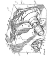
- Figure 1 is a perspective view partly in section, of a gas turbine engine exhaust noise suppressor in accordance with the present invention;
- Figure 2 is a cross-sectional view to an enlarged scale taken along the line 2-2 in Figure 1;
- Figure 2A is a fragmentary cross-sectional view to an enlarged scale taken along the line 2-2 of Figure 1, but illustrating a portion of an alternative embodiment of the noise suppressor in which eduction cooling apparatus is connected to its outlet;
- Figure 3 is a cross-sectional view taken along the line 3-3 in Figure 1;
- Figure 3A is a view similar to Figure 3 illustrating an alternative embodiment of the noise suppressor in which its inlet duct work is modified; and
- Figure 4 is a fragmentary, enlarged scale cross-sectional view taken through the noise suppressor along the offset line 4-4 in Figure 2.
- Figures 1 to 3 show a
compact sound attenuator 10 which embodies principles of the present invention and which is used both to attenuate the noise associated withexhaust gas 12 discharged from a gas turbine engine (not shown) and to cool the exhaust gas prior to its discharge to atmosphere. Theattenuator 10 comprises ahousing 14 having a generally rectangular cross-section,opposite end walls lower side walls rear side walls baffle member 28 into first andsecond subchambers transfer passage 34. Thebaffle 28 is positioned between theend walls lower side wall 22, terminating in anupper end 36 which defines the lower boundary of thetransfer passage 34. - Spaced inwardly from the
left end wall 18, and extending parallel thereto, is a perforated dividingwall 38 which defines with the end wall 18 acavity 40 which is filled with a suitable bulksound absorbing material 42. A hollowsound absorbing member 44 extends downwardly from theupper side wall 20 between the perforatedinterior wall 38 and thebaffle 28, and defines in the second subchamber 32 a sound absorbing flow path having a serpentine configuration and extending between thetransfer passage 34 and ahousing outlet 46 formed through theupper side wall 20 between theperforated wall 38 and thesound absorbing member 44. The hollowsound absorbing member 44 has a perforated outer wall section 48 which extends betweenhousing side walls baffle 28, a side wall portion 48b facing theperforated wall 38, and a rounded lower or inner end 48c which faces and is spaced upwardly from the lowerhousing side wall 22. The interior cavity defined by the curved wall 48 is filled with a suitable bulk sound-absorbingmaterial 50. As can be seen in Figure 2, the inner wall end 48c is positioned closer to the lowerhousing side wall 22 than is theinner end 36 of thebaffle 28. - A
curved wall 52, having a generally U-shaped cross-section, is positioned at the bottom ofsecond subchamber 32 and extends between theperforated wall 38 and thebaffle 28. Together with the curved end 48c of sound-absorbingmember 44, thecurved wall 52 serves to round off the lower end of the previously mentioned serpentine flow path, thereby reducing overall turning losses associated with such a flow path. The flow path extends from thetransfer passage 34 downwardly between thebaffle 28 and the perforated side wall 48a, to the left between thecurved wall 52 and curved inner wall end 48c and upwards between theperforated wall 38 and the perforated side wall 48b to thehousing outlet 46. - At the top of the
housing 14 there is a reactivesound attenuating chamber 54 which is defined by aninterior dividing wall 56 that is positioned inwardly from theupper side wall 20 and extends between thesound absorbing member 44 and thehousing end wall 16. The dividingwall 56 has a perforatedsection 58 which, as shown in Figure 2, extends rightwards from thesound absorbing member 44 to a central longitudinal portion of thewall 56. Aresonant sound attenuator 60 is positioned within the reactivesound attenuating chamber 54 and comprises alatticed wall structure 62 and a coveringwall 64. - The term "reactive", in the sound attenuation context used herein, means that the sound attenuation characteristics of the particular attenuator (i.e. the chamber 54) arise from, and are primarily effected by, its overall volume and configuration. Stated otherwise, the attenuation characteristics of a reactive attenuator are dimension-dominated. The term "resonant", on the other hand, means that the sound attenuation characteristics of the particular attenuator are, as to sound in flow thereto, resistance-dominated.
- The
latticed wall 62 has a lower side surface which is positioned against the upper surface of theperforated wall section 58 within thechamber 54. Perpendicularly extending lattice elements of thewall 62 define therein a multiplicity ofsound attenuating cells 66 which communicate with the first andsecond subchambers wall section 58. As can best be seen in Figures 2 and 3, thelatticed wall 62 extends completely between thehousing walls perforated wall section 58 uncovered so that there is direct communication between thechambers wall section 58 along the length L2 thereof. The height of thelatticed wall structure 62 is less than the height of thechamber 54 so that thechamber 54 extends above and overlaps the latticed wall along its entire length and width. Thesolid covering wall 64 is suitably secured to the upper side surface of thelatticed wall 62 thereby blocking off the upper ends of the multiplicity of the individualsound attenuating cells 66. -
Engine exhaust gas 12 andambient cooling air 68 are caused to flow into thefirst subchamber 30, and are mixed to form a cooled, dilutedexhaust gas flow 70, by means of a compact inletdiffuser duct structure 72. Theduct structure 72 includes a circularlycross-sectioned inlet duct 74 which extends inwards from thehousing wall 24 and terminates at its right end (as viewed in Figures 1 and 3) in a generally bell-shapedoutlet end 76 which is spaced to the left from thehousing wall 26 within thesubchamber 30. Immediately to the left of the bell-shapedoutlet end 76, theinlet duct 74 has a radially outwardly flareddiffusion section 78. At its left end, immediately adjacent thehousing wall 24 the inlet duct has an outwardly flaredsection 80 around its periphery. - Extending coaxially into this enlarged
inlet duct section 80 is an open ended, circularly cross-sectioned exhaust gasinlet stub duct 82. Theduct 82 is of a smaller diameter than themain inlet duct 74, and is secured to it by means of a circumferentially spaced series of small support struts 84. Thestub duct 82 defines with the flaredinlet section 80 an annular eduction coolingair inlet 86. - The third component of the
duct structure 72 is acore member 88 which has an elongate cylindricalcentral stem portion 90 of a diameter smaller than that of thestub duct 82, and a generally bell-shaped end portion 92. Thestem 90 extends coaxially within theconcentric ducts upstream end portion 94 which is received within thestub duct 82 and defines with it anannular inlet passage 96. The bell end portion of thecore 88 is positioned immediately adjacent thehousing wall 26 and has a surface curvature similar to that of theoutlet end portion 76 ofduct 74. Thecore 88 andduct 74 together define anannular flow passage 98 which terminates at its downstream end in an annular, radially outwardly facing discharge opening 100 positioned between the outer peripheries of the bell-shapedduct portions 76,92. Thestem portion 90 of thecore 88 is secured to thestub duct 82 and themain inlet duct 74 by circumferentially spaced series of support struts 102, 104 respectively, while the bell-shapedduct portions 76,92 are secured together by a circumferentially spaced series of axially extending support struts 106. - During operation of the
attenuator 10, hotengine exhaust gas 12 is forced into theinlet stub duct 82 and into themain inlet duct 74 via theannular passage 96. Entry of thehot exhaust gas 12 into theduct 74 draws a flow ofambient cooling air 68 into theduct 74, via theannular air inlet 86, by means of eduction. The educted cooling air is mixed with the hot exhaust gas and is carried thereby towards the annular discharge opening 100 through theannular passage 98. As the exhaust gas-cooling air mixture flows towards the annular outlet, it traverses the diffusion section of theannular passage 98 defined in part by the flaredwall section 78 of themain inlet duct 74. As can best be seen in Figure 3, as the exhaust gas-coolingair mixture 70 is forced closer to theoutlet 100 it is further diffused due to an additional widening of theannular passage 98 adjacent thedischarge opening 100. Finally, the exhaust gas-coolingair mixture 70 is forced radially outwardly through thedischarge opening 100 in to thefirst subchamber 30 which, as will be seen, functions as an expansion chamber for the cooledgas mixture 70. - The diffusion of the gas-
air mixture 70 in theannular passage 98 appreciably retards it velocity, thereby enhancing both further mixing and cooling of the flow streams 12 and 68, and reducing the exit velocity of the mixture from theannular discharge opening 100. This latter velocity reduction permits thedischarge opening 100 to be placed in relatively close proximity to the inner surfaces of the housing (as best illustrated in Figure 2) while at the same time avoiding excessive turbulence of the discharged mixture as it flows against the housing inner surfaces. - As the exhaust gas-cooling
air mixture 70 is discharged from theannular opening 100 into thesubchamber 30, themixture 70 is caused to expand abruptly within the chamber, thereby creating an acoustic propagation impedence mismatch between the flowing gas and the discharged gas. This impedence mismatch effects a low frequency noise attenuation within theexpansion chamber 30 which is particularly effective in reducing the "core" noise component generated by the turbine engine. The magnitude of this low frequency noise reduction is established by the ratio of the expansion chamber cross-sectional area to the diffuser exit area (i.e., the area of the discharge opening 100), while the lowest frequency at which significant attenuation is achieved is determined by the volume of thechamber 30. - The low frequency noise reduction resulting from the previously described impedence mismatch is the first of three noise reduction mechanisms uniquely provided by the
attenuator 10. The second noise reduction mechanism is the reactive and resonant sound attenuation provided by the reactivesound attenuating chamber 54 and theresonant attenuator structure 60, which as will be seen, are connected in a novel parallel and overlapping relationship. - More specifically, as the cooled
exhaust gas 70 is discharged into theexpansion chamber 30, residual noise in the gas is simultaneously transmitted into theresonant sound attenuator 60 via the portion L1 of theperforated wall 58, and into the reactivesound attenuating chamber 54 through the portion L2 of thewall 58. Thechamber 54 functions to attenuate reactively additional low frequency noise in the cooledgas 70, while thelatticed wall structure 62, with its coveringwall 64, functions to attenuate mid and high frequency noise. It should be noted that the reactivesound attenuating chamber 54 not only overlaps theresonant sound attenuator 60, but also extends beyond its inlet (i.e. the portion L2 of the perforated wall 58), in opposite directions (i.e. to the left and right of the wall inlet section L2 as shown in Figure 2). This two dimensional "offset" feature of thechamber 54 allows its reactive attenuating characteristics to be "tuned" conveniently by appropriately correlating the length L2, and the dimensional interrelationships between the volume ofchamber 54 and the length, width and height of theresonant attenuator 60. - A third and final sound attenuating mechanism is provided by the
baffle 28, theperforated end wall 38 and thesound absorbing member 44, and the serpentine discharge flow path which they collectively define. Subsequent to its discharge into theexpansion chamber 30, the cooledexhaust gas 70 is forced over theupper baffle end 36, downwards between thebaffle 28 and thesound absorbing member 44, around the lower end 48c of the sound absorbing member, upwards between thesound absorbing member 44 and theperforated end wall 38, and outwards through thehousing outlet 46. While following this serpentine flow path, residual mid and high frequency noise in the cooledexhaust gas 70 is absorptively removed. Additionally, thesound absorbing member 44 provides line-of-sight general sound attenuation between theupper baffle end 36 and thehousing outlet 46. - In this way, the
sound attenuator 10 very effectively attenuates both core and turbine noise from the turbineengine exhaust gas 12. The attenuator can accomplish this desirable result via its unique three fold sound suppression technique and uses a very compact structure which may be easily sized and configured to the precisely matched (from an overall sound attenuation standpoint) to a variety of turbine engines. Moreover, in addition to sound attenuation, the apparatus causes thehot exhaust gas 12 to be eduction cooled within the attenuator's housing (which is itself also cooled by the educted air flow). Finally, it is important to note that despite its compactness, theattenuator 10 imposes only a relatively low pressure drop upon the exhaust gas traversing it, and may be inexpensively constructed essentially entirely from sheet metal and conventional bulk sound absorbing material. - In Figures 2A and 3A an
alternative embodiment 10a of theattenuator 10 is illustrated, components similar to those in the previously describedattenuator 10 being given the same reference numerals with the subscript "a". Theattenuator 10a is substantially identical to theattenuator 10, with the exception that the eduction cooling of the engine exhaust gas is performed externally of the attenuator at its downstream or outlet end. More specifically, the hotengine exhaust gas 12 is caused to flow into the expansion chamber 30a via a non-educted inlet anddiffusion duct 108 which has a circular cross-section and extends into the expansion chamber 30a through the housing wall 24a. Along a longitudinally central portion, theduct 108 has adiffusion section 110 which is tapered radially outwardly in the downstream direction. At its downstream end 112 thediffusion section 110 has an annular, outwardly flared portion which cooperates with a generally bell-shapedend member 114 to define an annular, radially outwardly facingoutlet passage 116 positioned immediately adjacent the housing wall 26a. Theend member 114 is secured to the diffusion duct end portion 112 by a circumferentially spaced series of support struts 118. - During operation of the
attenuator 10a, theengine exhaust gas 12 flows into theduct 108, is diffused and slowed along thediffusion portion 110, and is forced into the expansion chamber 30a via the radially facingannular outlet 116. From this point, the uncooled exhaust gas is forced through theattenuator 10a in a manner identical to that previously described in conjuction with theattenuator 10. However, as theexhaust gas 12 leaves the discharge opening 46a (Figure 2A), it enters a discharge duct 120 secured to the attenuator housing 14a at the outlet 46a. Surrounding the outer end of the discharge duct 120 is aneduction cooling duct 122. Theeduction cooling duct 122 is substantially larger in cross-section than the discharge duct 120 and is secured to it by a mutually spaced series of support struts 124. Discharge of theexhaust gas 12 into theeduction duct 122 draws a flow ofambient cooling air 68 into the lower end (as shown in Figure 2A) of the eduction duct. The coolingair flow 68 is mixed with theexhaust gas 12 in theduct 122 to form astream 70 of cooled exhaust gas which is discharged via theduct 122 to atmosphere. In this manner, a simplified duct work structure is provided for theattenuator 10a so that eduction cooling of the exhaust gas is effected subsequent to the sound attenuation.
Claims (11)
Applications Claiming Priority (2)
| Application Number | Priority Date | Filing Date | Title |
|---|---|---|---|
| US06/846,771 US4747467A (en) | 1986-04-01 | 1986-04-01 | Turbine engine noise suppression apparatus and methods |
| US846771 | 1986-04-01 |
Publications (3)
| Publication Number | Publication Date |
|---|---|
| EP0240318A2 true EP0240318A2 (en) | 1987-10-07 |
| EP0240318A3 EP0240318A3 (en) | 1989-11-29 |
| EP0240318B1 EP0240318B1 (en) | 1993-12-15 |
Family
ID=25298902
Family Applications (1)
| Application Number | Title | Priority Date | Filing Date |
|---|---|---|---|
| EP87302803A Expired - Lifetime EP0240318B1 (en) | 1986-04-01 | 1987-03-31 | Apparatus and method for suppression of turbine engine noise |
Country Status (6)
| Country | Link |
|---|---|
| US (1) | US4747467A (en) |
| EP (1) | EP0240318B1 (en) |
| JP (1) | JP2599588B2 (en) |
| CA (1) | CA1293198C (en) |
| DE (1) | DE3788449T2 (en) |
| ES (1) | ES2049213T3 (en) |
Cited By (1)
| Publication number | Priority date | Publication date | Assignee | Title |
|---|---|---|---|---|
| AU712578B2 (en) * | 1997-09-25 | 1999-11-11 | Mitsubishi Hitachi Power Systems, Ltd. | Gas turbine exhaust passage and damper system for same |
Families Citing this family (30)
| Publication number | Priority date | Publication date | Assignee | Title |
|---|---|---|---|---|
| US4944362A (en) * | 1988-11-25 | 1990-07-31 | General Electric Company | Closed cavity noise suppressor |
| US5162620A (en) * | 1989-11-28 | 1992-11-10 | Allied-Signal Inc. | Dual flow turbine engine muffler |
| DE3940381A1 (en) * | 1989-12-06 | 1991-06-13 | Pks Engineering | Duct for gas turbine exhaust gases - consists of outer and inner wall, insulating layer and cover plates and rails |
| US5837890A (en) * | 1994-12-12 | 1998-11-17 | Aero Systems Engineering, Inc. | Jet engine test cell structure |
| US6009180A (en) * | 1996-09-17 | 1999-12-28 | The Boeing Company | Fluidic element noise and vibration control constructs and methods |
| KR100301864B1 (en) * | 1999-06-15 | 2001-09-22 | 이준상 | a silencer of air compressor |
| US6387247B1 (en) | 1999-09-03 | 2002-05-14 | Shell Oil Company | Feed injection system for catalytic cracking process |
| US6397759B1 (en) * | 2000-05-11 | 2002-06-04 | Bombardier Inc. | Non-electric locomotive and enclosure for a turbine engine for a non-electric locomotive |
| US6571910B2 (en) | 2000-12-20 | 2003-06-03 | Quiet Storm, Llc | Method and apparatus for improved noise attenuation in a dissipative internal combustion engine exhaust muffler |
| US6742339B2 (en) * | 2002-09-06 | 2004-06-01 | General Electric Company | Methods and apparatus for exhausting gases from gas turbine engines |
| US7482705B2 (en) * | 2003-05-12 | 2009-01-27 | Piercey Iii Gerald S | Generator support plenum |
| US7080514B2 (en) * | 2003-08-15 | 2006-07-25 | Siemens Power Generation,Inc. | High frequency dynamics resonator assembly |
| US7383918B1 (en) * | 2003-12-31 | 2008-06-10 | Vitai Link, Inc. | Noise suppressor exhaust sound attenuation overhaul and repair kit |
| US20080129053A1 (en) * | 2004-05-12 | 2008-06-05 | Piercey Gerald S | Engine-generator set |
| US7762374B2 (en) * | 2006-11-22 | 2010-07-27 | Honeywell International Inc. | Turbine engine diffusing exhaust muffler |
| US7980357B2 (en) * | 2007-02-02 | 2011-07-19 | Officepower, Inc. | Exhaust silencer for microturbines |
| JP5215735B2 (en) * | 2008-05-30 | 2013-06-19 | 三菱重工業株式会社 | Gas turbine exhaust equipment |
| JP5448762B2 (en) | 2009-12-02 | 2014-03-19 | 三菱重工業株式会社 | Combustion burner for gas turbine |
| US20110308481A1 (en) * | 2010-06-16 | 2011-12-22 | Bradford White Corporation | Water heater blower housing |
| US20150069763A1 (en) * | 2013-09-10 | 2015-03-12 | General Electric Company | Load cover |
| US20160258358A1 (en) * | 2015-03-02 | 2016-09-08 | Sikorsky Aircraft Corporation | High turning angle ejector cooled turbine engine exhaust duct |
| US10184372B2 (en) | 2016-05-23 | 2019-01-22 | Honeywell International Inc. | Exhaust systems and methods for gas turbine engine |
| US10077118B2 (en) * | 2016-06-06 | 2018-09-18 | Hamilton Sundstrand Corporation | Integral rat generator cooling holes |
| US11883358B2 (en) | 2018-03-05 | 2024-01-30 | Leggett & Platt Canada Co. | Pneumatic massage system |
| US11432995B2 (en) | 2018-08-29 | 2022-09-06 | Leggett & Platt Canada Co. | Pneumatic massage |
| FR3078744B1 (en) * | 2018-03-08 | 2020-11-20 | Safran Nacelles | ACTIVE ACOUSTIC EMISSION MITIGATION SYSTEM FOR A TURBOREACTOR CONTAINING CONTROLLED TURBINES |
| US11039975B2 (en) | 2018-08-29 | 2021-06-22 | Leggett & Platt Canada Co. | Pneumatic massage |
| CN115175827A (en) | 2020-02-24 | 2022-10-11 | 舒克拉贝恩多夫有限公司 | Airbag device for seat and method for manufacturing same |
| DE102020002160A1 (en) * | 2020-04-03 | 2021-10-07 | Bomag Gmbh | Vibrating plate with hood optimized for noise reduction |
| DE102020131039B4 (en) | 2020-11-24 | 2026-04-02 | Tenneco Gmbh | Exhaust gas cooling device |
Family Cites Families (30)
| Publication number | Priority date | Publication date | Assignee | Title |
|---|---|---|---|---|
| US1975861A (en) * | 1931-07-02 | 1934-10-09 | Oldberg Mfg Company | Muffler |
| US2685936A (en) * | 1950-08-08 | 1954-08-10 | Lockheed Aircraft Corp | Sound reduction equipment for use with jet-propulsion units |
| US2828189A (en) * | 1954-02-04 | 1958-03-25 | Oxy Catalyst Inc | Device for catalytically purifying exhaust gases |
| US2832430A (en) * | 1954-04-23 | 1958-04-29 | Robert S Coombs | Sound muffler device for exhausts of internal combustion engines |
| US2798743A (en) * | 1955-03-23 | 1957-07-09 | Svenska Aeroplan Ab | Flexible coupling device for connecting jet-engine-powered aircraft to ground mounted silencers |
| US2810449A (en) * | 1955-04-12 | 1957-10-22 | North American Aviation Inc | Sound abatement device for jet engines |
| US2940537A (en) * | 1957-01-04 | 1960-06-14 | Gen Sound Control Inc | Means and techniques for silencing sound energy |
| US2958390A (en) * | 1957-03-18 | 1960-11-01 | Owens Illinois Glass Co | Sound muffling device |
| US3525418A (en) * | 1959-10-05 | 1970-08-25 | Gen Acoustics Corp | Noise suppression system |
| US3159238A (en) * | 1960-12-01 | 1964-12-01 | Curtiss Wright Corp | Diffuser screen with heat-insulating rungs for exhaust noise suppressor for reactionengines |
| DE1476539A1 (en) * | 1963-01-21 | 1969-07-10 | Junkers & Co | Silencer, especially for a burner system with pulsating combustion |
| DE1231957B (en) * | 1964-01-04 | 1967-01-05 | Gruenzweig & Hartmann | Silencer for the gas jet emerging from a mouth at high speed |
| US3227240A (en) * | 1964-05-04 | 1966-01-04 | Gen Electric | Air mingling sound suppressor for jet engine |
| US3415337A (en) * | 1966-04-20 | 1968-12-10 | Gen Electric | Air injector device for air-cooled noise suppressors |
| US3396535A (en) * | 1966-06-16 | 1968-08-13 | Louis W. Milos | Engine exhaust system |
| US3485039A (en) * | 1967-12-29 | 1969-12-23 | Hugh Oliver | Exhaust gas treating device |
| US3620329A (en) * | 1969-12-31 | 1971-11-16 | Glasrock Products | Jet engine noise suppressor |
| US3715009A (en) * | 1970-08-17 | 1973-02-06 | Gen Acoustics Corp | Jet engine noise suppression system |
| US3688865A (en) * | 1970-11-17 | 1972-09-05 | Cloyd D Smith | Jet engine noise suppressor |
| US3709319A (en) * | 1971-10-06 | 1973-01-09 | Gen Electric | Resonator chamber silencer for gas turbine |
| US3738448A (en) * | 1971-12-13 | 1973-06-12 | Bolt Beranek & Newman | Sound silencing method and apparatus |
| US3941206A (en) * | 1974-05-08 | 1976-03-02 | Burgess Industries Incorporated | Noise attenuating snubber |
| RO62594A2 (en) * | 1975-06-12 | 1975-08-01 | Inst Pentru Creatie Stintific | METHOD AND DEVICE FOR THE ATTENUATION OF THE NOISE OF THE GAS JET |
| US4128769A (en) * | 1976-09-27 | 1978-12-05 | The Garrett Corporation | Eductor muffler |
| US4371054A (en) * | 1978-03-16 | 1983-02-01 | Lockheed Corporation | Flow duct sound attenuator |
| US4244441A (en) * | 1979-07-31 | 1981-01-13 | The Garrett Corporation | Broad band acoustic attenuator |
| JPS58169299U (en) * | 1982-05-07 | 1983-11-11 | ヤンマーディーゼル株式会社 | gas turbine generator |
| US4596307A (en) * | 1983-04-26 | 1986-06-24 | Challis Louis A | Fluid discharge silencer |
| DE3406282C2 (en) * | 1984-02-22 | 1986-04-30 | Adam Opel AG, 6090 Rüsselsheim | Reflection silencers for internal combustion engines |
| US4645032A (en) * | 1985-09-05 | 1987-02-24 | The Garrett Corporation | Compact muffler apparatus and associated methods |
-
1986
- 1986-04-01 US US06/846,771 patent/US4747467A/en not_active Expired - Lifetime
-
1987
- 1987-02-24 CA CA000530431A patent/CA1293198C/en not_active Expired - Fee Related
- 1987-03-24 JP JP62070165A patent/JP2599588B2/en not_active Expired - Lifetime
- 1987-03-31 ES ES87302803T patent/ES2049213T3/en not_active Expired - Lifetime
- 1987-03-31 DE DE87302803T patent/DE3788449T2/en not_active Expired - Fee Related
- 1987-03-31 EP EP87302803A patent/EP0240318B1/en not_active Expired - Lifetime
Cited By (1)
| Publication number | Priority date | Publication date | Assignee | Title |
|---|---|---|---|---|
| AU712578B2 (en) * | 1997-09-25 | 1999-11-11 | Mitsubishi Hitachi Power Systems, Ltd. | Gas turbine exhaust passage and damper system for same |
Also Published As
| Publication number | Publication date |
|---|---|
| JPS62237039A (en) | 1987-10-17 |
| ES2049213T3 (en) | 1994-04-16 |
| DE3788449T2 (en) | 1994-04-07 |
| US4747467A (en) | 1988-05-31 |
| EP0240318A3 (en) | 1989-11-29 |
| DE3788449D1 (en) | 1994-01-27 |
| CA1293198C (en) | 1991-12-17 |
| EP0240318B1 (en) | 1993-12-15 |
| JP2599588B2 (en) | 1997-04-09 |
Similar Documents
| Publication | Publication Date | Title |
|---|---|---|
| EP0240318B1 (en) | Apparatus and method for suppression of turbine engine noise | |
| US6415887B1 (en) | Refractive wave muffler | |
| CA2072118C (en) | Dual flow turbine engine muffler | |
| CA1269334A (en) | Compact muffler apparatus and associated methods | |
| US4108276A (en) | Vent silencer | |
| US4537277A (en) | Silencer for high velocity gas flow | |
| US4128769A (en) | Eductor muffler | |
| US4180141A (en) | Distributor for gas turbine silencers | |
| US6739426B2 (en) | Low-noise pressure reduction system | |
| US3185252A (en) | Jet engine noise attenuator | |
| US4113048A (en) | Method of and device for attenuating the noise radiated by gas jets | |
| US3286787A (en) | Turbine exhaust silencer | |
| US4203502A (en) | Muffler | |
| GB2132269A (en) | Silencer for high velocity gas flow | |
| US7350620B2 (en) | Compact silencer | |
| US7191868B2 (en) | Combined silencer and spark arrester | |
| US5076393A (en) | Engine exhaust muffler | |
| US4196793A (en) | Method of and device for attenuating the noise radiated by gas jets | |
| US5730946A (en) | Combined catalytic converter and muffler | |
| US4282950A (en) | Muffler | |
| GB2041083A (en) | Silencer for an internal combustion engine | |
| GB2241286A (en) | Central heating boiler exhaust silencing | |
| KR0125788Y1 (en) | Sub muffler structure | |
| SU369611A1 (en) | ACOUSTIC FILTER | |
| SU1000562A1 (en) | Gas flow noise silencer |
Legal Events
| Date | Code | Title | Description |
|---|---|---|---|
| PUAI | Public reference made under article 153(3) epc to a published international application that has entered the european phase |
Free format text: ORIGINAL CODE: 0009012 |
|
| AK | Designated contracting states |
Kind code of ref document: A2 Designated state(s): DE ES FR GB IT SE |
|
| PUAL | Search report despatched |
Free format text: ORIGINAL CODE: 0009013 |
|
| AK | Designated contracting states |
Kind code of ref document: A3 Designated state(s): DE ES FR GB IT SE |
|
| 17P | Request for examination filed |
Effective date: 19900507 |
|
| 17Q | First examination report despatched |
Effective date: 19901012 |
|
| RAP1 | Party data changed (applicant data changed or rights of an application transferred) |
Owner name: ALLIED-SIGNAL INC. |
|
| GRAA | (expected) grant |
Free format text: ORIGINAL CODE: 0009210 |
|
| AK | Designated contracting states |
Kind code of ref document: B1 Designated state(s): DE ES FR GB IT SE |
|
| REF | Corresponds to: |
Ref document number: 3788449 Country of ref document: DE Date of ref document: 19940127 |
|
| ET | Fr: translation filed | ||
| ITF | It: translation for a ep patent filed | ||
| REG | Reference to a national code |
Ref country code: ES Ref legal event code: FG2A Ref document number: 2049213 Country of ref document: ES Kind code of ref document: T3 |
|
| PLBE | No opposition filed within time limit |
Free format text: ORIGINAL CODE: 0009261 |
|
| STAA | Information on the status of an ep patent application or granted ep patent |
Free format text: STATUS: NO OPPOSITION FILED WITHIN TIME LIMIT |
|
| RAP2 | Party data changed (patent owner data changed or rights of a patent transferred) |
Owner name: ALLIEDSIGNAL INC. |
|
| 26N | No opposition filed | ||
| EAL | Se: european patent in force in sweden |
Ref document number: 87302803.9 |
|
| PGFP | Annual fee paid to national office [announced via postgrant information from national office to epo] |
Ref country code: DE Payment date: 19991229 Year of fee payment: 14 |
|
| PGFP | Annual fee paid to national office [announced via postgrant information from national office to epo] |
Ref country code: GB Payment date: 20000204 Year of fee payment: 14 |
|
| PGFP | Annual fee paid to national office [announced via postgrant information from national office to epo] |
Ref country code: SE Payment date: 20000302 Year of fee payment: 14 |
|
| PGFP | Annual fee paid to national office [announced via postgrant information from national office to epo] |
Ref country code: FR Payment date: 20000303 Year of fee payment: 14 |
|
| PGFP | Annual fee paid to national office [announced via postgrant information from national office to epo] |
Ref country code: ES Payment date: 20000317 Year of fee payment: 14 |
|
| PG25 | Lapsed in a contracting state [announced via postgrant information from national office to epo] |
Ref country code: GB Free format text: LAPSE BECAUSE OF NON-PAYMENT OF DUE FEES Effective date: 20010331 |
|
| PG25 | Lapsed in a contracting state [announced via postgrant information from national office to epo] |
Ref country code: SE Free format text: LAPSE BECAUSE OF NON-PAYMENT OF DUE FEES Effective date: 20010401 |
|
| PG25 | Lapsed in a contracting state [announced via postgrant information from national office to epo] |
Ref country code: ES Free format text: LAPSE BECAUSE OF NON-PAYMENT OF DUE FEES Effective date: 20010402 |
|
| GBPC | Gb: european patent ceased through non-payment of renewal fee |
Effective date: 20010331 |
|
| PG25 | Lapsed in a contracting state [announced via postgrant information from national office to epo] |
Ref country code: FR Free format text: LAPSE BECAUSE OF NON-PAYMENT OF DUE FEES Effective date: 20011130 |
|
| EUG | Se: european patent has lapsed |
Ref document number: 87302803.9 |
|
| REG | Reference to a national code |
Ref country code: FR Ref legal event code: ST |
|
| PG25 | Lapsed in a contracting state [announced via postgrant information from national office to epo] |
Ref country code: DE Free format text: LAPSE BECAUSE OF NON-PAYMENT OF DUE FEES Effective date: 20020101 |
|
| REG | Reference to a national code |
Ref country code: ES Ref legal event code: FD2A Effective date: 20030203 |
|
| PG25 | Lapsed in a contracting state [announced via postgrant information from national office to epo] |
Ref country code: IT Free format text: LAPSE BECAUSE OF NON-PAYMENT OF DUE FEES;WARNING: LAPSES OF ITALIAN PATENTS WITH EFFECTIVE DATE BEFORE 2007 MAY HAVE OCCURRED AT ANY TIME BEFORE 2007. THE CORRECT EFFECTIVE DATE MAY BE DIFFERENT FROM THE ONE RECORDED. Effective date: 20050331 |