EP0240182A2 - Linse - Google Patents
Linse Download PDFInfo
- Publication number
- EP0240182A2 EP0240182A2 EP87301959A EP87301959A EP0240182A2 EP 0240182 A2 EP0240182 A2 EP 0240182A2 EP 87301959 A EP87301959 A EP 87301959A EP 87301959 A EP87301959 A EP 87301959A EP 0240182 A2 EP0240182 A2 EP 0240182A2
- Authority
- EP
- European Patent Office
- Prior art keywords
- lens
- light
- refractive
- adjacent
- angle
- Prior art date
- Legal status (The legal status is an assumption and is not a legal conclusion. Google has not performed a legal analysis and makes no representation as to the accuracy of the status listed.)
- Withdrawn
Links
- 239000012780 transparent material Substances 0.000 claims abstract description 7
- 230000003287 optical effect Effects 0.000 claims description 11
- 230000007704 transition Effects 0.000 claims description 6
- 230000002093 peripheral effect Effects 0.000 claims description 5
- 238000013459 approach Methods 0.000 claims description 4
- 239000012141 concentrate Substances 0.000 abstract description 3
- 239000000463 material Substances 0.000 description 9
- 230000005540 biological transmission Effects 0.000 description 6
- 238000004519 manufacturing process Methods 0.000 description 4
- 239000004417 polycarbonate Substances 0.000 description 3
- 229920000515 polycarbonate Polymers 0.000 description 3
- 229920006397 acrylic thermoplastic Polymers 0.000 description 2
- XAGFODPZIPBFFR-UHFFFAOYSA-N aluminium Chemical compound [Al] XAGFODPZIPBFFR-UHFFFAOYSA-N 0.000 description 2
- 229910052782 aluminium Inorganic materials 0.000 description 2
- 238000005452 bending Methods 0.000 description 2
- 239000011248 coating agent Substances 0.000 description 2
- 238000000576 coating method Methods 0.000 description 2
- 229920003229 poly(methyl methacrylate) Polymers 0.000 description 2
- ISXSCDLOGDJUNJ-UHFFFAOYSA-N tert-butyl prop-2-enoate Chemical compound CC(C)(C)OC(=O)C=C ISXSCDLOGDJUNJ-UHFFFAOYSA-N 0.000 description 2
- 241000321453 Paranthias colonus Species 0.000 description 1
- 239000004743 Polypropylene Substances 0.000 description 1
- 239000004793 Polystyrene Substances 0.000 description 1
- 239000004820 Pressure-sensitive adhesive Substances 0.000 description 1
- 230000006750 UV protection Effects 0.000 description 1
- NIXOWILDQLNWCW-UHFFFAOYSA-N acrylic acid group Chemical group C(C=C)(=O)O NIXOWILDQLNWCW-UHFFFAOYSA-N 0.000 description 1
- 230000001154 acute effect Effects 0.000 description 1
- 230000000295 complement effect Effects 0.000 description 1
- 238000000748 compression moulding Methods 0.000 description 1
- 230000007423 decrease Effects 0.000 description 1
- 230000001419 dependent effect Effects 0.000 description 1
- 239000011521 glass Substances 0.000 description 1
- 230000010354 integration Effects 0.000 description 1
- 239000010410 layer Substances 0.000 description 1
- 238000000034 method Methods 0.000 description 1
- 238000000465 moulding Methods 0.000 description 1
- 239000002245 particle Substances 0.000 description 1
- 230000000704 physical effect Effects 0.000 description 1
- 229920000642 polymer Polymers 0.000 description 1
- 229920001155 polypropylene Polymers 0.000 description 1
- -1 polypropylenes Polymers 0.000 description 1
- 229920002223 polystyrene Polymers 0.000 description 1
- 229920002635 polyurethane Polymers 0.000 description 1
- 239000004814 polyurethane Substances 0.000 description 1
- 229920000915 polyvinyl chloride Polymers 0.000 description 1
- 230000010076 replication Effects 0.000 description 1
Images


Classifications
-
- G—PHYSICS
- G02—OPTICS
- G02B—OPTICAL ELEMENTS, SYSTEMS OR APPARATUS
- G02B3/00—Simple or compound lenses
-
- G—PHYSICS
- G02—OPTICS
- G02B—OPTICAL ELEMENTS, SYSTEMS OR APPARATUS
- G02B3/00—Simple or compound lenses
- G02B3/02—Simple or compound lenses with non-spherical faces
- G02B3/08—Simple or compound lenses with non-spherical faces with discontinuous faces, e.g. Fresnel lens
-
- F—MECHANICAL ENGINEERING; LIGHTING; HEATING; WEAPONS; BLASTING
- F21—LIGHTING
- F21V—FUNCTIONAL FEATURES OR DETAILS OF LIGHTING DEVICES OR SYSTEMS THEREOF; STRUCTURAL COMBINATIONS OF LIGHTING DEVICES WITH OTHER ARTICLES, NOT OTHERWISE PROVIDED FOR
- F21V5/00—Refractors for light sources
Definitions
- the present invention relates to a lens of a transparent material, and in one aspect to a low F/number polymeric catadioptric lens for use in a light fixture.
- catadioptric Fresnel-type lenses including a catadioptric portion consisting of a plurality of two-faceted prisms as, for example, disclosed in a summary on "TIR FRESNEL LENSES" by Dr. Lawrence W. James, reported on pages 215-221 of the proceedings for the Tenth Photovoltaic Concentrator Project Integration Meeting, Albuquerque, New Mexico, April 6 & 7, 1983 and prepared by Sandia National Laboratories.
- Each prism has a refractive surface and a reflective surface, to form the lenses' structured surfaces to refract and reflect light from a light source striking those structured surfaces.
- such lenses have included conventional Fresnel-type portions at their centers and terminating where the efficiency of the conventional portions approaches the efficiency of the catadioptric portions of the lenses.
- such lenses have suffered from the inability of the radial outer peripheral prisms in the catadioptric portions to properly refract all of the light incident upon each refractive surface at high incident angles to be internally reflected by each reflective surface.
- this inability restricts the lenses' speeds, (i.e. F/numbers), or the efficiency of large angle bending of light rays.
- the present invention provides a lens that maintains high transmission efficiency at extremely low F/numbers.
- the lens is made of a transparent material, and includes a structured surface on one side and a smooth surface on the opposite side.
- the structured surface includes a plurality of three-faceted prisms arranged side by side to form a plurality of radial or linear ridges and grooves depending upon the type of light source, i.e. point or linear.
- each of the three-faceted prisms has a reflective surface adjacent to a refractive surface and a riser adjacent to the refractive surface.
- Each reflective surface of the prism is inclined at an angle to the smooth surface of the lens to totally internally reflect and direct incident light striking the reflective surface.
- Each refractive surface is inclined at an angle to its adjacent riser.
- the degree of inclination of each refractive surface and each adjacent reflective surface is such that high-angle incident light upon each refractive surface is refracted toward each reflective surface. This refracted light is then intemally reflected by each reflective surface, disposed at the predetermined angle, within each three-faceted prism to direct the light out of the lens through the smooth surface at the desired angle. It should also be appreciated, that light may be incident on the smooth surface, and reflected and refracted out of the lens through the structured surface to, for example, gather, concentrate or disperse the light.
- the lens of the present invention is that it can be easily integrated into present light fixtures to boost their efficiency or to reduce their depths, i.e. make them more compact.
- a light fixture comprises a generally opaque housing including a central cavity. At least one side of the housing includes an optical window in which a lens of the present invention is positioned.
- a light source is located within the housing cavity for supplying light to the optical window in which the lens is positioned.
- the structured surface of the lens is adjacent to-the light source so that incident light is transmitted through the lens by a combination of refraction and reflection. This ability is particularly useful, for example, in taillamps or spotlights.
- a reflector may be associated with the central cavity to reflect light back towards the light source to increase the efficiency.
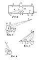
- a lens of the present invention may be used in a light fixture 22 for directing light from a light source 24.
- the light fixture 22 includes a housing 26 having an optical window 28 and an inner cavity 30 in which the light source 24 is supported for supplying light to the optical window 28.
- the lens 20 is positioned within the optical window 28 and is made of a transparent material having a structured surface 34 on one side and a smooth surface 36 on the opposite side.
- a positive condensing lens is illustrated in Figure 2.
- the structured surface 34 of the lens is positioned adjacent the light source 24 and includes at its periphery a catadioptric portion 35 consisting of a plurality of three-faceted prisms 38 arranged side by side to form a plurality of ridges 40 and grooves 42.
- the three-faceted prisms 38 are arranged side by side to form either radial or linear ridges 40 and grooves 42 depending upon whether a point or linear light source 24 is used, whereby light rays A are transmitted through the lens.
- the lens 20 of the present invention may have areas, such as a central refractive portion 50 as illustrated in Figure 3, with, for example, a configuration like a conventional Fresnel-type lens, as illustrated in U.S. Patent Nos. 3,744,882 (Forster, Jr.), 3,293,982 (Appeldorn) and 4,076,384 (Deml, et al.) the disclosures of which are hereby incorporated by reference.
- the central refractive portion 50 is located at the center of the lens 20 adjacent to the peripheral catadioptric portion 35 consisting of the three-faceted prisms 38 illustrated in Figure 2.
- the central refractive portion includes a plurality of refracting elements 52 each having a riser 54 and a refractive surface 56 whereby light rays B are transmitted through the lens.
- the central refractive portion 50 and the peripheral catadioptric portion 35 are separated by a transition zone 70, illustrated in Figure 4, located where the efficiency of the refracting elements 52 approaches the efficiency of the three-faceted prisms 38.
- the transition zone 70 may comprise one or more two-faceted prisms 72 having a reflective surface 74 and an adjacent refractive surface 76 whereby light rays C are transmitted through the lens.
- each three-faceted prism 38 of the catadioptric portion 35 includes a reflective surface 84 adjacent to a refractive surface 86 and a riser 88 adjacent to the refractive surface 86.
- Each reflective surface 84 is inclined at an angle to the smooth surface 36 to totally internally reflect and direct incident light striking each reflective surface 84.
- Each refractive surface 86 is inclined at an obtuse angle to each adjacent riser 88 and at an acute angle to each reflective surface 84. The degree of inclination is such that high-angle incident light from the light source 24 is refracted at each refractive surface 86. This high-angle incident light is refracted at an angle such that the light that strikes each adjacent reflective surface 84, is intemally reflected by each reflective surface 84 within each three-faceted prism 38, and is directed out of the lens 20.
- the tens 20 may include a plurality of concentric rings, wherein each ring includes at least two three-faceted prisms 38 in which the degree of inclination of the refractive surfaces 86 to the adjacent risers 88 is constant within each ring and varies from ring to ring over the diameter of the lens 20.
- the degree of inclination of the refractive surfaces 86 decreases with increasing radius of the lens 20 outward.
- all of the refractive surfaces 86 and reflective surfaces 84 focus the light to a design-determined region or regions. This relationship is demonstrated by the following equations:
- the incident angle ⁇ is chosen arbitrarily, and the angle ⁇ 2 , of the reflective surface 74 is chosen such that the exiting ray angle ⁇ 1 ' is the desired angle for the particular purpose of the lens.
- a third facet or optically inactive riser 88 is provided using a minimum included angle T between the riser 88 and the reflective surface of an adjoining groove. In this way, the wasted area can be minimized. It is also desirable that a positive relief angle p be formed if the lens is to be replicated by standard molding techniques. Negative relief angles up to the angle of the limiting ray angle ⁇ , will further increase efficiency for some cases, but if the relief angle p is negative, replication will be difficult or impossible.
- the actual transmission through the three-faceted prisms 38 of the catadioptric portion 35 must be calculated and the angle of the refractive surface 86 chosen so that first surface Fresnel reflection losses at the refractive surface 86 are balanced against geometric losses caused by light striking a portion of the optically inactive riser 88.
- the angle ⁇ 1 of the refractive surface 86 can be determined from the following: Utilizing these formulae one obtains the following angles defining the three-faceted prism geometry, in degrees, for a unit Focal length lens:
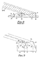
- the three-faceted prisms 38 transmit substantially more of the light incident upon their refractive surfaces 86 than do the prior art two-faceted prisms 72, illustrated in Figures 6 and 8.
- the ray angle 92 becomes large and a two-faceted prism 72 of the prior art is designed so that rays are refracted and then totally intemally reflected out of the smooth surface 36, a large portion of the ray bundle will not strike the reflective surface 74 and will be lost.
- the three-faceted prisms 38 of the present invention are designed with substantially the same angles as the two-faceted prisms 72 illustrated in Figure 8, on the refractive surface 86(,e,) and reflective surface 84( ⁇ 2 ), more of the light will be transmitted through the lens in the intended direction because the inactive area of the two-faceted prisms 72 has been substantially reduced by using the riser 88 of the three-faceted design.
- the relationship between the central refractive portion 50 and the catadioptric portion 35 is demonstrated by the graph in Figure 10 which shows a comparison of transmission efficiency verses F/numbers for a conventional Fresnel-type lens 50 and the lens 20 of the present invention in which the structured surface 34 consists entirely of the three-faceted prisms 38 of the catadioptric portion.
- the conventional design is most efficient at lower angles of incident light (i.e. higher F/numbers), whereas the catadioptric design is most efficient at higher angles of incident light (i.e. lower F/numbers).
- the transition zone 70 should be positioned where these two efficiencies are approximately equal.
- the lens 20 may be designed in accordance with the above to provide that the exiting rays are perpendicular or non-perpendicular to the smooth surface 36.
- the particular material used for the lens 20 may vary, but it is intended that in most applications the material be generally rigid. It is, however, essential that the material be transparent, and preferably homogeneous and isotropic, for example, polymeric materials or glass.
- Useful polymeric materials for this purpose are commercially available acrylics and polycarbonates having nominal indices of refraction of 1.49 and 1.58, respectively.
- Other useful polymers are polypropylenes, polyurethanes, polystyrenes, polyvinyl chlorides, and the like.
- the particular material selected is not significant to the invention hereof, so long as it provides the described function. Normally, the manufacturers of this product will select the best commercially available material based upon price, application and manufacturing process.
- acrylics and polycarbonates are of particular interest because of their physical properties, i.e. weatherability, ultraviolet resistance, dimensional stability, and temperature tolerance.
- the thickness of the lens 20 is not particularly essential to the present invention, however, the applicability of the lens 20 for a particular use, such as a vehicle taillamp, may be dependent upon its thickness.
- the lens 20 provides for large diameter spotlights having small focal lengths.
- the lens 20 may be used to gather or concentrate light incident on the smooth surface 36 for solar concentrators and the like.
- the lens 20 may be used as a field lens for use in, for example, overhead projectors or projection televisions of the types illustrated in U.S. Patent Nos. 3,293,982 (Appeldorn), 3,830,556 (Bratkowski) and 4,054,907 (Itoh, et al.), the disclosures of which are hereby incorporated by reference.
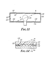
- the lens 20 may be used in a light fixture 22, as illustrated in Figures 1 and 11 wherein the lens 20 is positioned in the optical window 28 of the housing 26.
- the housing may be made by forming, bending or extruding a suitable material, such as aluminum or polycarbonate.
- a diffuser 110 may be provided in the optical window 28 to redistribute or disperse the light in a desired fashion, as illustrated in Figure 11.
- the diffuser may be incorporated into the lens 20 of the present invention by adding diffusing or reflecting particles, to the transparent material, or by forming pillows as an integral part of the smooth surface 36 (not shown).
- a reflector such as, a spherical reflective Fresnel-type lens 120 of a polymeric material, may be associated with the inner surface 122 of the housing 26 to reflect light incident upon the reflector back towards the light source.
- the reflector 120 includes a structured surface 126 on one side and a smooth surface 128 on the opposite side.
- the structured surface may include a reflective coating 130, for example, by vapor coating aluminum, and consist of a plurality of reflective elements 132 each having a reflective step 134 and an adjacent riser 136.
- the reflective steps 134 are inclined to reflect the incident light back towards the light source 24 where it passes through the light source to strike the structured surface 34 of the lens 20 of the present invention.
- light ray D will be reflected back towards the light source 24 by reflector 120.
- the reflector 120 may be adhered to the housing by a suitable pressure-sensitive adhesive layer 138.
- a suitable light source 24 may include an artificial source, as disclosed, for example, in U.S. Patent No. 4,081,667 (Lewin et al.), the disclosure of which is hereby incorporated by reference.
Landscapes
- Physics & Mathematics (AREA)
- General Physics & Mathematics (AREA)
- Optics & Photonics (AREA)
- Engineering & Computer Science (AREA)
- General Engineering & Computer Science (AREA)
- Optical Elements Other Than Lenses (AREA)
- Illuminated Signs And Luminous Advertising (AREA)
- Lenses (AREA)
- Polarising Elements (AREA)
- Preparing Plates And Mask In Photomechanical Process (AREA)
- Prostheses (AREA)
Applications Claiming Priority (2)
| Application Number | Priority Date | Filing Date | Title |
|---|---|---|---|
| US84732286A | 1986-04-02 | 1986-04-02 | |
| US847322 | 1986-04-02 |
Publications (2)
| Publication Number | Publication Date |
|---|---|
| EP0240182A2 true EP0240182A2 (de) | 1987-10-07 |
| EP0240182A3 EP0240182A3 (de) | 1990-05-09 |
Family
ID=25300331
Family Applications (1)
| Application Number | Title | Priority Date | Filing Date |
|---|---|---|---|
| EP87301959A Withdrawn EP0240182A3 (de) | 1986-04-02 | 1987-03-06 | Linse |
Country Status (4)
| Country | Link |
|---|---|
| EP (1) | EP0240182A3 (de) |
| JP (1) | JPS62238501A (de) |
| KR (1) | KR870010410A (de) |
| CA (1) | CA1293880C (de) |
Cited By (6)
| Publication number | Priority date | Publication date | Assignee | Title |
|---|---|---|---|---|
| EP0426411A3 (en) * | 1989-10-30 | 1991-08-28 | Minnesota Mining And Manufacturing Company | Light fixture with beam shaping lens |
| EP0476893A1 (de) * | 1990-09-19 | 1992-03-25 | Minnesota Mining And Manufacturing Company | Catadioptrische Linse mit gleichmässigem Intensitätsprofil |
| EP0499946A1 (de) * | 1991-02-20 | 1992-08-26 | AT&T Corp. | LED mit Vielfach-Facettenreflektor zur Erhöhung des Kopplungsgrades und der Justiertoleranz |
| EP0829738A3 (de) * | 1996-09-17 | 1999-01-07 | Komy Kogei Co., Ltd. | Flacher Reflektor mit einer Fresnellinse für Flugzeuge |
| EP1089094A1 (de) * | 1999-09-30 | 2001-04-04 | Valeo Vision | Verfahren zum Herstellen refraktiver Elemente und refraktive Elemente für einer Beleuchtungseinrichtung |
| DE102008062287A1 (de) * | 2008-12-09 | 2010-06-17 | Fresnel Optics Gmbh | Fokussierendes optisches Element und seine Verwendung |
Families Citing this family (1)
| Publication number | Priority date | Publication date | Assignee | Title |
|---|---|---|---|---|
| JP2001337206A (ja) * | 2000-05-26 | 2001-12-07 | Toppan Printing Co Ltd | フレネルレンズ |
Family Cites Families (4)
| Publication number | Priority date | Publication date | Assignee | Title |
|---|---|---|---|---|
| FR797223A (fr) * | 1935-01-26 | 1936-04-23 | Dispositif réflecteur catadioptrique | |
| FR1088331A (fr) * | 1952-08-22 | 1955-03-07 | Elastic Stop Nut Corp | Lentilles, notamment lentilles catadioptriques; procédés et dispositifs de fabrication de telles lentilles |
| US3883733A (en) * | 1974-03-18 | 1975-05-13 | Voevodsky John | Optical construction of a lens |
| DE3317519A1 (de) * | 1983-05-13 | 1984-11-15 | Robert Bosch Gmbh, 7000 Stuttgart | Lichtsammelplatte |
-
1987
- 1987-03-04 CA CA000531072A patent/CA1293880C/en not_active Expired - Lifetime
- 1987-03-06 EP EP87301959A patent/EP0240182A3/de not_active Withdrawn
- 1987-04-01 JP JP62080853A patent/JPS62238501A/ja active Pending
- 1987-04-01 KR KR870003077A patent/KR870010410A/ko not_active Ceased
Cited By (6)
| Publication number | Priority date | Publication date | Assignee | Title |
|---|---|---|---|---|
| EP0426411A3 (en) * | 1989-10-30 | 1991-08-28 | Minnesota Mining And Manufacturing Company | Light fixture with beam shaping lens |
| EP0476893A1 (de) * | 1990-09-19 | 1992-03-25 | Minnesota Mining And Manufacturing Company | Catadioptrische Linse mit gleichmässigem Intensitätsprofil |
| EP0499946A1 (de) * | 1991-02-20 | 1992-08-26 | AT&T Corp. | LED mit Vielfach-Facettenreflektor zur Erhöhung des Kopplungsgrades und der Justiertoleranz |
| EP0829738A3 (de) * | 1996-09-17 | 1999-01-07 | Komy Kogei Co., Ltd. | Flacher Reflektor mit einer Fresnellinse für Flugzeuge |
| EP1089094A1 (de) * | 1999-09-30 | 2001-04-04 | Valeo Vision | Verfahren zum Herstellen refraktiver Elemente und refraktive Elemente für einer Beleuchtungseinrichtung |
| DE102008062287A1 (de) * | 2008-12-09 | 2010-06-17 | Fresnel Optics Gmbh | Fokussierendes optisches Element und seine Verwendung |
Also Published As
| Publication number | Publication date |
|---|---|
| JPS62238501A (ja) | 1987-10-19 |
| EP0240182A3 (de) | 1990-05-09 |
| KR870010410A (ko) | 1987-11-30 |
| CA1293880C (en) | 1992-01-07 |
Similar Documents
| Publication | Publication Date | Title |
|---|---|---|
| US4755921A (en) | Lens | |
| US5949933A (en) | Lenticular illumination system | |
| US7925129B2 (en) | Compact optics for concentration, aggregation and illumination of light energy | |
| US8412010B2 (en) | Compact optics for concentration and illumination systems | |
| JP3532215B2 (ja) | マイクロプリズムのアレイを用いる照明系 | |
| CN100437166C (zh) | 具有聚光器的视亮度增强膜 | |
| TW419572B (en) | Back-coupled illumination system with light recycling | |
| EP2743740B1 (de) | Linsenelement und lichtemittierende vorrichtung damit | |
| US7672549B2 (en) | Solar energy concentrator | |
| EP0235447B1 (de) | Lichtleiter mit totaler interner Reflexion | |
| JP3488467B2 (ja) | マイクロプリズムのアレイを用いる照明系 | |
| US20030016539A1 (en) | High efficiency non-imaging optics | |
| CN101163841B (zh) | 具有可变棱镜的管状天棚照明屋顶 | |
| EP2519978B1 (de) | Pv-konzentrator mit optischer abgestufter linse und korrespondierendes entwurfsverfahren | |
| JP3678744B2 (ja) | 日光照明用の形作られたフィルム及びその使用方法 | |
| JP2008004558A (ja) | 照明装置 | |
| US7068446B2 (en) | Compact non-imaging light collector | |
| EP0240182A2 (de) | Linse | |
| KR20010075051A (ko) | 에지-발광되는 도파관 및 빛을 추출하고 배향하는 부재를별개로 갖는 발광 시스템 | |
| KR101059759B1 (ko) | 프리즘 하이브리드 태양광 집광기 | |
| CN2407368Y (zh) | 直纹透镜 | |
| GB2260825A (en) | Optical fibre associated with faceted optical elements | |
| CN114019666B (zh) | 一种全反射式led显微照明配光元件 | |
| CN215636984U (zh) | 一种透镜及灯具 | |
| EP1774385A1 (de) | Kompaktes, nichtabbildungs-lichtsystem |
Legal Events
| Date | Code | Title | Description |
|---|---|---|---|
| PUAI | Public reference made under article 153(3) epc to a published international application that has entered the european phase |
Free format text: ORIGINAL CODE: 0009012 |
|
| AK | Designated contracting states |
Kind code of ref document: A2 Designated state(s): DE ES FR GB IT SE |
|
| PUAL | Search report despatched |
Free format text: ORIGINAL CODE: 0009013 |
|
| AK | Designated contracting states |
Kind code of ref document: A3 Designated state(s): DE ES FR GB IT SE |
|
| 17P | Request for examination filed |
Effective date: 19900628 |
|
| 17Q | First examination report despatched |
Effective date: 19920810 |
|
| STAA | Information on the status of an ep patent application or granted ep patent |
Free format text: STATUS: THE APPLICATION IS DEEMED TO BE WITHDRAWN |
|
| 18D | Application deemed to be withdrawn |
Effective date: 19940303 |
|
| RIN1 | Information on inventor provided before grant (corrected) |
Inventor name: NELSON, JOHN C.C/O MINNESOTA MINING AND |