EP0240126A2 - Multipack for flanged containers - Google Patents
Multipack for flanged containers Download PDFInfo
- Publication number
- EP0240126A2 EP0240126A2 EP87301427A EP87301427A EP0240126A2 EP 0240126 A2 EP0240126 A2 EP 0240126A2 EP 87301427 A EP87301427 A EP 87301427A EP 87301427 A EP87301427 A EP 87301427A EP 0240126 A2 EP0240126 A2 EP 0240126A2
- Authority
- EP
- European Patent Office
- Prior art keywords
- panel
- web
- hinged
- package
- container
- Prior art date
- Legal status (The legal status is an assumption and is not a legal conclusion. Google has not performed a legal analysis and makes no representation as to the accuracy of the status listed.)
- Withdrawn
Links
Images


Classifications
-
- B—PERFORMING OPERATIONS; TRANSPORTING
- B65—CONVEYING; PACKING; STORING; HANDLING THIN OR FILAMENTARY MATERIAL
- B65D—CONTAINERS FOR STORAGE OR TRANSPORT OF ARTICLES OR MATERIALS, e.g. BAGS, BARRELS, BOTTLES, BOXES, CANS, CARTONS, CRATES, DRUMS, JARS, TANKS, HOPPERS, FORWARDING CONTAINERS; ACCESSORIES, CLOSURES, OR FITTINGS THEREFOR; PACKAGING ELEMENTS; PACKAGES
- B65D5/00—Rigid or semi-rigid containers of polygonal cross-section, e.g. boxes, cartons or trays, formed by folding or erecting one or more blanks made of paper
- B65D5/20—Rigid or semi-rigid containers of polygonal cross-section, e.g. boxes, cartons or trays, formed by folding or erecting one or more blanks made of paper by folding-up portions connected to a central panel from all sides to form a container body, e.g. of tray-like form
-
- B—PERFORMING OPERATIONS; TRANSPORTING
- B65—CONVEYING; PACKING; STORING; HANDLING THIN OR FILAMENTARY MATERIAL
- B65D—CONTAINERS FOR STORAGE OR TRANSPORT OF ARTICLES OR MATERIALS, e.g. BAGS, BARRELS, BOTTLES, BOXES, CANS, CARTONS, CRATES, DRUMS, JARS, TANKS, HOPPERS, FORWARDING CONTAINERS; ACCESSORIES, CLOSURES, OR FITTINGS THEREFOR; PACKAGING ELEMENTS; PACKAGES
- B65D71/00—Bundles of articles held together by packaging elements for convenience of storage or transport, e.g. portable segregating carrier for plural receptacles such as beer cans or pop bottles; Bales of material
- B65D71/40—Bundles of articles held together by packaging elements for convenience of storage or transport, e.g. portable segregating carrier for plural receptacles such as beer cans or pop bottles; Bales of material comprising a plurality of articles held together only partially by packaging elements formed by folding a blank or several blanks
- B65D71/42—Bundles of articles held together by packaging elements for convenience of storage or transport, e.g. portable segregating carrier for plural receptacles such as beer cans or pop bottles; Bales of material comprising a plurality of articles held together only partially by packaging elements formed by folding a blank or several blanks formed by folding a single blank into a single layer element
Definitions
- This invention relates to a package incorporating a group of flanged containers in which end panel structures are provided across the package ends and to blanks for forming such packages.
- One aspect of the invention provides a package incorporating at least one container having side and end walls and outwardly projecting flanges at the top thereof, which package comprises a top panel overlying the top of the container, securing strips hinged to opposed longitudinal side edges of said top panel and secured to the undersides of adjacent container flanges so that at least portions of said flanges are interposed between portions of said top panel and said securing strips and side panel means hinged to said securing strips and extending downwardly to cover at least portions of the exposed side walls of the container, characterised by an end panel structure at each end of the package comprising an end panel hinged to oppposed ends of the top panel and flanking the end walls of the container and a web panel structure at each of the opposite ends of said end panel, each web panel structure comprising an end web panel hinged to said end panel and a part secured in face contacting relationship with the adjacent side panel means so as to maintain the end panel in flanking relationship with the end wall of the container.
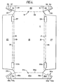
- an elongate blank 10 formed from paperboard or similar foldable sheet material.
- the blank comprises a top panel 12 to each of the longitudinal edges of which is hinged integral securing strips 14 and 16 along fold lines 18 and 20 respectively.
- a side panel 22 is hinged to securing strip 14 along fold line 24 and a side panel 26 is hinged to securing strip 16 along fold line 28.
- the blank is adapted to be applied to a group of flanged containers 'C' of the type in which the top flanges of the containers are frangibly connected together.
- the blank includes end panels at each end of the package and in order to maintain these panels in the desired position when the package is formed i.e. against the outward facing end of the containers, the end panels are included in an end panel structure 30, 30a respectively, at each of the opposite ends. of the blank which ensure that the end panels are held substantially perpendicular to the top panel across the ends of the package.
- End panel structure 30 comprises an end panel 32 integrally hinged to one transverse edge of top panel 12 along transverse fold line 34, and web panel structures 36 and 38 respectively.
- Web panel structure 36 comprises side web panel 40 which is hinged to the adjacent edge of side panel 22 along transverse fold line 42 and end web panel 44 hinged to the adjacent edge of end panel 32 along oblique fold line 46.
- Side web panel 40 and end web panel 44 are hinged together- along short oblique fold line 48.
- web panel structure 38 comprises side web panel 50 which is hinged to the adjacent edge of side panel 26 along transverse fold line 52 and end web panel 54 hinged to the adjacent edge of end panel 32 along oblique fold line 56.
- Side web panel 50 and end web panel 54 are hinged together along a short oblique fold line 58.
- the fold line 34 by which end panel 32 is hinged to the top panel 12 is offset outwardly by dimension 'd' relative to an imaginary line 'n', notional extensions of which at each end contain the transverse edges of side panels 22 and 26 and the transverse fold lines 42 and 52 to provide for automatic tuck-...
- the blank 10 is applied to one or more groups of flanged containers so that the top panel 12 lies on the tops of the containers in each group.
- the securing strips 14 and 16 are then brought into abutment with and secured (as by ultrasonic heat sealing or gluing) to the underfaces of the flanges 'f' of the containers in each of the rows R', R 2 by causing the blank to be folded along fold lines 18, 24 and 20, 28.
- This folding operation brings each of the side panels 22 and 26 into abutment or close relationship with the exposed sides of the adjacent containers.
- Web panel structure 38 is similarly folded so that web panels 50 and 54 lie adjacent the inside face of side panel 26.
- web panels 40 and 44 and web panels 50 and 54 may lie in overlapping relationship adjacent the inside face of end panel 32.
- the opposite end panel structure 30a is similarly folded as described above.
- the apertures A and A 2 defined in part by the side and end web panels 40, 44 and 50, 54 are relatively large openings thereby forming relatively long and narrow web panels.
- the web panels are narrowest at the hinged connections 48 and 58 respectively.
- the relatively narrow web panel construction is provided so that when those panels are folded into their overlapping relationship the combined board thickness is not such as to tend to push the edges and corners of the package side panels outwardly, which would detract from the visual appearance of the finished package and also make it more difficult to pack in trays or cases.
- the short oblique fold lines 48 and 58 produce a web structure which is of low resilience thereby reducing the bias in the folded web panels which tend to unfold the end panel structure 30.
- the same criteria apply to the opposite end panel structure 30a.
- a modified blank 11 also is formed from paperboard or similar foldable sheet material.
- Blank 11 comprises a top panel 13 to each of the longitudinal edges of which is hinged integral securing strips 15 and 17 along fold lines 19 and 21 respectively.
- a side panel 23 is hinged to securing strip 15 along fold line 25 and an opposite side panel 27 is hinged to securing strip 17 along fold line 29.
- blank 11 is adapted to be applied to a group of flanged containers C1 of the type in which the top flanges of the containers are frangibly connected together.
- a different end panel structure 31, 31a respectively is provided.
- End panel structure 31 comprises an end panel 33 integrally hinged to one transverse edge of top panel 13 along transverse fold line 35, and further comprises web panel structures 37 and 39 respectively.
- Web panel structure 37 comprises end web panel 41 which is hinged to the adjacent edge of end panel 33 along longitudinal fold line 43 and fixing tab 45 hinged along fold line 47 to that edge of the end web panel 41 which is adjacent side panel 23.
- web panel structure 39 comprises end web panel 49 which is hinged to the adjacent edge of end panel 33 along longitudinal fold line 51 and fixing tab 53 hinged along fold line 55 to that edge of the end web panel 49 which is adjacent side panel 27.
- a rectangular opening 57 is struck from the blank close to that end of the side panel 23 which is adjacent the fixing tab 45 and has one of its longer edges along fold line 19 and its opposite edge within the side panel 23.
- a similar opening 59 is struck in a corresponding position at the opposite side of the blank.
- the blank 11 is applied to one or more groups of flanged containers so that the top panel 13 lies on the tops of the containers in each group.
- the end panel 33 is then folded downwardly across one end of the part-formed package and each of the web panel structures 37, 39 are folded rearwardly about fold lines 43, 51 respectively i.e. towards the opposite end of the package.
- This folding action brings the fixing tabs 45 and 47 into a position in which they are disposed beneath the apertures 57 and 59 respectively.
- the side panels 23 and 27 are then folded downwardly so that the fixing tabs are located in registry with the apertures 57, 59.
- the securing strips 15, 17 and the fixing tabs are then brought into abutment with and secured (as by ultrasonic heat sealing or gluing) to the underfaces of the flanges f1 of the containers in each of the rows R3, R4 by folding the blank along fold lines 19, 25; 21, 29; 47 and 55.
- This folding and securing operation brings and maintains each of the end panels 33 and 33a into abutment or close relationship with the exposed end faces of the adjacent containers.
- the blanks may be applied to a single flanged container rather then a group of interconnected flanged containers and in some applications it is envisaged that the top panel of the blank may provide the top closure cover of the containers or container as the case may be.
Abstract
A package (P) incorporating a group of flanged containers (c) in two rows in which a top panel (12) overlies the tops of the containers, securing strip panels (14, 16) are secured to the undersides of the container flanges (f) in each row (R', R2), side panels (22, 26) flank the exposed sides of the containers in each row and end panel structures (30, 30a) flank the endmost sides of the containers and tie together the side walls across the ends of the package.
Description
- This invention relates to a package incorporating a group of flanged containers in which end panel structures are provided across the package ends and to blanks for forming such packages.
- One aspect of the invention provides a package incorporating at least one container having side and end walls and outwardly projecting flanges at the top thereof, which package comprises a top panel overlying the top of the container, securing strips hinged to opposed longitudinal side edges of said top panel and secured to the undersides of adjacent container flanges so that at least portions of said flanges are interposed between portions of said top panel and said securing strips and side panel means hinged to said securing strips and extending downwardly to cover at least portions of the exposed side walls of the container, characterised by an end panel structure at each end of the package comprising an end panel hinged to oppposed ends of the top panel and flanking the end walls of the container and a web panel structure at each of the opposite ends of said end panel, each web panel structure comprising an end web panel hinged to said end panel and a part secured in face contacting relationship with the adjacent side panel means so as to maintain the end panel in flanking relationship with the end wall of the container.
- Another aspect of the invention provides a packaging blank for forming a package as defined in the immediately preceding paragraph which blank comprises a top panel, side panel means hinged to opposite side edges of the top panel by integral panel strips and an end panel structure at each end of said blank, each end panel structure comprising an end panel hinged to the top panel and a web panel structure at each of its opposite ends, characterised in that each web panel structure comprises an end web panel hinged to an adjacent edge of the end panel and a fixing tab hinged to an edge of said end web panel and in that an opening is formed in each of said side panel means positioned such that each fixing tab can be brought into registry with a respective one of said openings when each of said end panel structures is brought into a substantially perpendicular attitude relative to said top panel and the web panel structures at one end of the blank are folded towards the web panel structures at the opposite end of the blank.
- Two embodiments of the invention will now be described, by way of example, with reference to the accompanying drawings, in which:-
- FIGURE 7 is a plan view from which one package according to the invention is formed;
- FIGURE 2 is a perspective view of the blank of Figure 1 showing the top panel of the blank seated on a group of containers with the end panel structure of the blank partially folded;
- FIGURE 3 is a perspective view of the same one packa.ge in which folding of the end panel structure is complete;
- FIGURE 4 is a plan view of another blank from which another package according to the invention is formed;
- FIGURE 5 is a perspective view of the blank of Figure 4 showing the top panel of the blank seated on a group of containers with the end panel structure of the blank partially folded;
- FIGURE 6 is a perspective view of the modified package in which folding of the end panel structure is complete; and
- FIGURE 6a is a cross-sectional view taken on the line 'x-x' in Figure 6.
- Referring first to Figure 1, there is shown an elongate blank 10 formed from paperboard or similar foldable sheet material. The blank comprises a
top panel 12 to each of the longitudinal edges of which is hingedintegral securing strips fold lines side panel 22 is hinged to securingstrip 14 alongfold line 24 and aside panel 26 is hinged to securingstrip 16 alongfold line 28. - The blank is adapted to be applied to a group of flanged containers 'C' of the type in which the top flanges of the containers are frangibly connected together.
- The blank includes end panels at each end of the package and in order to maintain these panels in the desired position when the package is formed i.e. against the outward facing end of the containers, the end panels are included in an
end panel structure -
End panel structure 30 comprises anend panel 32 integrally hinged to one transverse edge oftop panel 12 alongtransverse fold line 34, andweb panel structures Web panel structure 36 comprisesside web panel 40 which is hinged to the adjacent edge ofside panel 22 alongtransverse fold line 42 andend web panel 44 hinged to the adjacent edge ofend panel 32 alongoblique fold line 46.Side web panel 40 andend web panel 44 are hinged together- along shortoblique fold line 48. Likewise,web panel structure 38 comprisesside web panel 50 which is hinged to the adjacent edge ofside panel 26 alongtransverse fold line 52 and end web panel 54 hinged to the adjacent edge ofend panel 32 along oblique fold line 56.Side web panel 50 and end web panel 54 are hinged together along a shortoblique fold line 58. - The
fold line 34 by whichend panel 32 is hinged to thetop panel 12 is offset outwardly by dimension 'd' relative to an imaginary line 'n', notional extensions of which at each end contain the transverse edges ofside panels transverse fold lines - ing of the web structures as is described below with particular reference to Figures 2 and 3. The opposite end panel structure is of similar arrangement and like parts are designated like reference numerals with the addition of suffix 'a'.
- A blank and a package of similar construction, but without end panels is described in our published European patent application No 0 141 631 and the formation of a package of the present invention is similar in some respects.
- To form the completed package, the blank 10 is applied to one or more groups of flanged containers so that the
top panel 12 lies on the tops of the containers in each group. Thesecuring strips fold lines side panels - When
end panel 32 is folded substantially perpendicular with respect to top panel 12 (into abutment or close relationship with the exposed sides of the adjacent containers) the offset disposition offold line 34 as previously described causes each of the side and end web panels ofweb panel structures fold lines fold line fold lines side web panel 40 is brought into overlapping relationship withside panel 22 andend web panel 44 is brought into overlapping relationship withside web panel 40 whereby both web panels ofstructure 36 lie adjacent the inside face ofside panel 22. Web panel structure 38 is similarly folded so thatweb panels 50 and 54 lie adjacent the inside face ofside panel 26. Alternatively, by folding in an opposeddirection web panels web panels 50 and 54 may lie in overlapping relationship adjacent the inside face ofend panel 32. Of course, the oppositeend panel structure 30a is similarly folded as described above. - It will be seen (Figure 1) that the apertures A and A2 defined in part by the side and
end web panels connections oblique fold lines end panel structure 30. Of course, the same criteria apply to the oppositeend panel structure 30a. - Referring to Figure 4, a modified blank 11 also is formed from paperboard or similar foldable sheet material. Blank 11 comprises a
top panel 13 to each of the longitudinal edges of which is hingedintegral securing strips fold lines side panel 23 is hinged to securingstrip 15 alongfold line 25 and anopposite side panel 27 is hinged to securingstrip 17 along fold line 29. - As in the previous embodiment, blank 11 is adapted to be applied to a group of flanged containers C1 of the type in which the top flanges of the containers are frangibly connected together. However, in this embodiment, a different
end panel structure 31, 31a respectively is provided. -
End panel structure 31 comprises anend panel 33 integrally hinged to one transverse edge oftop panel 13 alongtransverse fold line 35, and further comprisesweb panel structures Web panel structure 37 comprisesend web panel 41 which is hinged to the adjacent edge ofend panel 33 alonglongitudinal fold line 43 and fixingtab 45 hinged alongfold line 47 to that edge of theend web panel 41 which isadjacent side panel 23. Likewise,web panel structure 39 comprisesend web panel 49 which is hinged to the adjacent edge ofend panel 33 alonglongitudinal fold line 51 and fixingtab 53 hinged alongfold line 55 to that edge of theend web panel 49 which isadjacent side panel 27. - A
rectangular opening 57 is struck from the blank close to that end of theside panel 23 which is adjacent thefixing tab 45 and has one of its longer edges alongfold line 19 and its opposite edge within theside panel 23. Asimilar opening 59 is struck in a corresponding position at the opposite side of the blank. - The opposite end of the blank is of like construction and like parts have like reference numerals with the addition of suffix 'a'.
- Referring now to Figures 5, 6 and 6a, to form the completed package, the blank 11 is applied to one or more groups of flanged containers so that the
top panel 13 lies on the tops of the containers in each group. Theend panel 33 is then folded downwardly across one end of the part-formed package and each of theweb panel structures fold lines fixing tabs apertures side panels apertures securing strips fold lines end panels - It is envisaged that in either of the embodiments described the blanks may be applied to a single flanged container rather then a group of interconnected flanged containers and in some applications it is envisaged that the top panel of the blank may provide the top closure cover of the containers or container as the case may be.
Claims (6)
1. A package incorporating at least one container having side and end walls and outwardly projecting flanges at the top thereof, which package comprises a top panel overlying the top of the container, securing strips hinged to opposed longitudinal side edges of said top panel and secured to the undersides of adjacent container flanges so that at least portions of said flanges are interposed between portions of said top panel and said securing strips and side panel means hinged to said securing strips and extending downwardly to cover at least portions of the exposed side walls of the container, characterised by an end panel structure at each end of the package comprising an end panel hinged to opposed ends of the top panel and flanking the end walls of the container and a web panel structure at each of the opposite ends of said end panel, each web panel structure comprising an end web panel hinged to said end panel and a part secured in face contacting relationship with the adjacent side panel means so as to maintain the end panel in flanking relationship with the end wall of the container.
2. The package according to claim 1, further characterised in that said part of the web panel structure comprises a fixing tab hinged to the end web panel and secured to the underside of the adjacent container flange.
3. The package according to claim 2, further characterised in that the securing strip has an opening adjacent the ends thereof and in that said fixing tab is disposed within said opening.
4. The package according to claim 1, further characterised in that said part of the web panel structure comprises a side web panel hinged to the end web panel and to the side panel means.
5. The package according to claim 4, further characterised in that the end web panel and the side web panel of each web panel structure are disposed in overlapping relationship and lie adjacent the inside face of the associated side panel means.
6. A packaging blank for forming a package as defined in claim 1, which blank comprises a top panel having opposing sides and ends, securing strips hinged to opposite sides of the top panel, side panel means hinged to the securing strips, and an end panel structure provid?d at opposing ends of said top panel, each end panel structure comprising an end panel hinged to the top panel and a web panel structure extending laterally therefrom, characterised in that the web panel structure comprises an end web panel hinged to the end panel and a fixing tab hinged to said end web panel and in that an opening is formed in each of said securing strips and positioned such that said fixing tab can be brought into registry with a respective one of said openings when said end panel structures are brought into a substantially perpendicular attitude relative to said top panel and the web panel structures are folded inwardly.
Applications Claiming Priority (2)
| Application Number | Priority Date | Filing Date | Title |
|---|---|---|---|
| GB8604411 | 1986-02-21 | ||
| GB868604411A GB8604411D0 (en) | 1986-02-21 | 1986-02-21 | Multipack |
Publications (2)
| Publication Number | Publication Date |
|---|---|
| EP0240126A2 true EP0240126A2 (en) | 1987-10-07 |
| EP0240126A3 EP0240126A3 (en) | 1988-10-12 |
Family
ID=10593492
Family Applications (1)
| Application Number | Title | Priority Date | Filing Date |
|---|---|---|---|
| EP87301427A Withdrawn EP0240126A3 (en) | 1986-02-21 | 1987-02-19 | Multipack for flanged containers |
Country Status (8)
| Country | Link |
|---|---|
| EP (1) | EP0240126A3 (en) |
| JP (1) | JPS62235071A (en) |
| KR (1) | KR870007824A (en) |
| AU (1) | AU6910387A (en) |
| BR (1) | BR8700794A (en) |
| GB (1) | GB8604411D0 (en) |
| MX (1) | MX168701B (en) |
| PT (1) | PT84322B (en) |
Cited By (8)
| Publication number | Priority date | Publication date | Assignee | Title |
|---|---|---|---|---|
| EP0423699A1 (en) * | 1989-10-18 | 1991-04-24 | Europa Carton Aktiengesellschaft | Multi-package |
| EP0425135A2 (en) * | 1989-10-23 | 1991-05-02 | The Mead Corporation | Package incorporating containers |
| EP0712367A1 (en) * | 1994-06-14 | 1996-05-22 | Riverwood International Corporation | Article carrier with rounded corners and corresponding blank |
| EP0818397A1 (en) * | 1996-07-09 | 1998-01-14 | Riverwood International Corporation | Retaining device for rimmed articles |
| WO2009064951A2 (en) | 2007-11-15 | 2009-05-22 | Graphic Packaging International, Inc. | Package for containers |
| US8353398B2 (en) | 2009-12-18 | 2013-01-15 | Graphic Packaging International, Inc. | Package for beverage-type containers |
| US8464866B2 (en) | 2007-10-18 | 2013-06-18 | Graphic Packaging International, Inc. | Package for container |
| US9776750B2 (en) | 2011-08-19 | 2017-10-03 | Graphic Packaging International, Inc. | Apparatus and method for forming a carton |
Citations (3)
| Publication number | Priority date | Publication date | Assignee | Title |
|---|---|---|---|---|
| GB984450A (en) * | 1961-08-08 | 1965-02-24 | Print Processes Sales Ltd | Improvements in or relating to carriers for rimmed cylindrical cans |
| FR1444157A (en) * | 1965-05-19 | 1966-07-01 | Parisienne Impression | Grouping packaging forming protective cover for containers |
| US4304329A (en) * | 1980-09-02 | 1981-12-08 | Johns-Manville Corporation | Crown support carrier |
-
1986
- 1986-02-21 GB GB868604411A patent/GB8604411D0/en active Pending
-
1987
- 1987-02-19 EP EP87301427A patent/EP0240126A3/en not_active Withdrawn
- 1987-02-19 PT PT84322A patent/PT84322B/en unknown
- 1987-02-20 MX MX005306A patent/MX168701B/en unknown
- 1987-02-20 AU AU69103/87A patent/AU6910387A/en not_active Abandoned
- 1987-02-20 BR BR8700794A patent/BR8700794A/en unknown
- 1987-02-20 JP JP62036000A patent/JPS62235071A/en active Pending
- 1987-02-21 KR KR870001487A patent/KR870007824A/en not_active Application Discontinuation
Patent Citations (3)
| Publication number | Priority date | Publication date | Assignee | Title |
|---|---|---|---|---|
| GB984450A (en) * | 1961-08-08 | 1965-02-24 | Print Processes Sales Ltd | Improvements in or relating to carriers for rimmed cylindrical cans |
| FR1444157A (en) * | 1965-05-19 | 1966-07-01 | Parisienne Impression | Grouping packaging forming protective cover for containers |
| US4304329A (en) * | 1980-09-02 | 1981-12-08 | Johns-Manville Corporation | Crown support carrier |
Cited By (14)
| Publication number | Priority date | Publication date | Assignee | Title |
|---|---|---|---|---|
| EP0423699A1 (en) * | 1989-10-18 | 1991-04-24 | Europa Carton Aktiengesellschaft | Multi-package |
| EP0425135A2 (en) * | 1989-10-23 | 1991-05-02 | The Mead Corporation | Package incorporating containers |
| EP0425135A3 (en) * | 1989-10-23 | 1992-02-05 | The Mead Corporation | Package incorporating flanged containers |
| EP0712367A1 (en) * | 1994-06-14 | 1996-05-22 | Riverwood International Corporation | Article carrier with rounded corners and corresponding blank |
| EP0712367A4 (en) * | 1994-06-14 | 1997-02-26 | Riverwood Int Corp | Article carrier with rounded corners |
| EP0818397A1 (en) * | 1996-07-09 | 1998-01-14 | Riverwood International Corporation | Retaining device for rimmed articles |
| US8464866B2 (en) | 2007-10-18 | 2013-06-18 | Graphic Packaging International, Inc. | Package for container |
| WO2009064951A2 (en) | 2007-11-15 | 2009-05-22 | Graphic Packaging International, Inc. | Package for containers |
| EP2209724A4 (en) * | 2007-11-15 | 2011-04-06 | Graphic Packaging Int Inc | Package for containers |
| EP2209724A2 (en) * | 2007-11-15 | 2010-07-28 | Graphic Packaging International, Inc. | Package for containers |
| US8353398B2 (en) | 2009-12-18 | 2013-01-15 | Graphic Packaging International, Inc. | Package for beverage-type containers |
| US9359093B2 (en) | 2009-12-18 | 2016-06-07 | Graphic Packaging International, Inc. | Package for containers |
| US9776750B2 (en) | 2011-08-19 | 2017-10-03 | Graphic Packaging International, Inc. | Apparatus and method for forming a carton |
| US10766644B2 (en) | 2011-08-19 | 2020-09-08 | Graphic Packaging International, Llc | Apparatus and method for forming a carton |
Also Published As
| Publication number | Publication date |
|---|---|
| PT84322A (en) | 1987-03-01 |
| EP0240126A3 (en) | 1988-10-12 |
| AU6910387A (en) | 1987-08-27 |
| KR870007824A (en) | 1987-09-22 |
| JPS62235071A (en) | 1987-10-15 |
| MX168701B (en) | 1993-06-04 |
| BR8700794A (en) | 1987-12-15 |
| GB8604411D0 (en) | 1986-03-26 |
| PT84322B (en) | 1989-02-20 |
Similar Documents
| Publication | Publication Date | Title |
|---|---|---|
| US4582199A (en) | Carton and blank therefor | |
| AU679227B2 (en) | Article carrier reinforcing structure | |
| JP3066111B2 (en) | Can packaging containers | |
| US4566593A (en) | Carton formed from a plurality of packages | |
| EP0069508B1 (en) | Article carrier with dispensing feature | |
| US4339032A (en) | Bottle carrier with peripheral skirt | |
| AU751070B2 (en) | Handle arrangement for a carton | |
| KR960702406A (en) | ARTICLE CARRIER WITH ROUNDED CORNERS | |
| EP0391623B1 (en) | Carton with slot type carrying handle | |
| US3432090A (en) | Self-locking box | |
| US5107986A (en) | Wrap-around carrier with article retainer | |
| US5533667A (en) | Separable modular containers | |
| EP0515648B1 (en) | Wrap-around carrier with article retainer | |
| US4838479A (en) | Heavy duty carrying handle for a can carton | |
| US4437569A (en) | Shipping carton with case knife protection for inner cartons | |
| EP0240126A2 (en) | Multipack for flanged containers | |
| EP0044169A1 (en) | Carton for beverage containers | |
| US3989181A (en) | Partitioned container having self locking top and bottom forming flaps | |
| US4712726A (en) | Simulated gift wrap box | |
| US4238031A (en) | Edge protector | |
| EP1157938A1 (en) | Two-tier cup package with end closure-retaining panel | |
| US5699958A (en) | Carton flap retention arrangement | |
| USRE32956E (en) | Carton and blank therefor | |
| EP0368518B1 (en) | Multipacks for flanged containers | |
| JPH059303Y2 (en) |
Legal Events
| Date | Code | Title | Description |
|---|---|---|---|
| PUAI | Public reference made under article 153(3) epc to a published international application that has entered the european phase |
Free format text: ORIGINAL CODE: 0009012 |
|
| AK | Designated contracting states |
Kind code of ref document: A2 Designated state(s): AT BE CH CH DE ES FR GB IT NL SE |
|
| PUAL | Search report despatched |
Free format text: ORIGINAL CODE: 0009013 |
|
| AK | Designated contracting states |
Kind code of ref document: A3 Designated state(s): AT BE CH CH DE ES FR GB IT NL SE |
|
| STAA | Information on the status of an ep patent application or granted ep patent |
Free format text: STATUS: THE APPLICATION IS DEEMED TO BE WITHDRAWN |
|
| 18D | Application deemed to be withdrawn |
Effective date: 19890413 |
|
| RIN1 | Information on inventor provided before grant (corrected) |
Inventor name: CHAUSSADAS, JEAN |