EP0240100A1 - A jaw arrangement for a microbend sensor - Google Patents
A jaw arrangement for a microbend sensor Download PDFInfo
- Publication number
- EP0240100A1 EP0240100A1 EP19870300384 EP87300384A EP0240100A1 EP 0240100 A1 EP0240100 A1 EP 0240100A1 EP 19870300384 EP19870300384 EP 19870300384 EP 87300384 A EP87300384 A EP 87300384A EP 0240100 A1 EP0240100 A1 EP 0240100A1
- Authority
- EP
- European Patent Office
- Prior art keywords
- jaws
- jaw
- optical fibre
- projections
- flat areas
- Prior art date
- Legal status (The legal status is an assumption and is not a legal conclusion. Google has not performed a legal analysis and makes no representation as to the accuracy of the status listed.)
- Granted
Links
- 239000013307 optical fiber Substances 0.000 claims abstract description 54
- 238000005452 bending Methods 0.000 claims abstract description 8
- 239000000463 material Substances 0.000 claims 1
- 238000006073 displacement reaction Methods 0.000 abstract description 3
- 238000005259 measurement Methods 0.000 abstract description 2
- 238000000034 method Methods 0.000 abstract 1
- 239000012530 fluid Substances 0.000 description 9
- 239000000835 fiber Substances 0.000 description 3
- 230000002411 adverse Effects 0.000 description 1
- XAGFODPZIPBFFR-UHFFFAOYSA-N aluminium Chemical compound [Al] XAGFODPZIPBFFR-UHFFFAOYSA-N 0.000 description 1
- 229910052782 aluminium Inorganic materials 0.000 description 1
- 230000008878 coupling Effects 0.000 description 1
- 238000010168 coupling process Methods 0.000 description 1
- 238000005859 coupling reaction Methods 0.000 description 1
- 239000013013 elastic material Substances 0.000 description 1
- 238000004519 manufacturing process Methods 0.000 description 1
- 230000003287 optical effect Effects 0.000 description 1
- 239000007779 soft material Substances 0.000 description 1
Images


Classifications
-
- G—PHYSICS
- G01—MEASURING; TESTING
- G01L—MEASURING FORCE, STRESS, TORQUE, WORK, MECHANICAL POWER, MECHANICAL EFFICIENCY, OR FLUID PRESSURE
- G01L1/00—Measuring force or stress, in general
- G01L1/24—Measuring force or stress, in general by measuring variations of optical properties of material when it is stressed, e.g. by photoelastic stress analysis using infrared, visible light, ultraviolet
-
- G—PHYSICS
- G02—OPTICS
- G02B—OPTICAL ELEMENTS, SYSTEMS OR APPARATUS
- G02B6/00—Light guides; Structural details of arrangements comprising light guides and other optical elements, e.g. couplings
- G02B6/10—Light guides; Structural details of arrangements comprising light guides and other optical elements, e.g. couplings of the optical waveguide type
- G02B6/14—Mode converters
-
- G—PHYSICS
- G01—MEASURING; TESTING
- G01D—MEASURING NOT SPECIALLY ADAPTED FOR A SPECIFIC VARIABLE; ARRANGEMENTS FOR MEASURING TWO OR MORE VARIABLES NOT COVERED IN A SINGLE OTHER SUBCLASS; TARIFF METERING APPARATUS; MEASURING OR TESTING NOT OTHERWISE PROVIDED FOR
- G01D5/00—Mechanical means for transferring the output of a sensing member; Means for converting the output of a sensing member to another variable where the form or nature of the sensing member does not constrain the means for converting; Transducers not specially adapted for a specific variable
- G01D5/26—Mechanical means for transferring the output of a sensing member; Means for converting the output of a sensing member to another variable where the form or nature of the sensing member does not constrain the means for converting; Transducers not specially adapted for a specific variable characterised by optical transfer means, i.e. using infrared, visible, or ultraviolet light
- G01D5/32—Mechanical means for transferring the output of a sensing member; Means for converting the output of a sensing member to another variable where the form or nature of the sensing member does not constrain the means for converting; Transducers not specially adapted for a specific variable characterised by optical transfer means, i.e. using infrared, visible, or ultraviolet light with attenuation or whole or partial obturation of beams of light
- G01D5/34—Mechanical means for transferring the output of a sensing member; Means for converting the output of a sensing member to another variable where the form or nature of the sensing member does not constrain the means for converting; Transducers not specially adapted for a specific variable characterised by optical transfer means, i.e. using infrared, visible, or ultraviolet light with attenuation or whole or partial obturation of beams of light the beams of light being detected by photocells
- G01D5/353—Mechanical means for transferring the output of a sensing member; Means for converting the output of a sensing member to another variable where the form or nature of the sensing member does not constrain the means for converting; Transducers not specially adapted for a specific variable characterised by optical transfer means, i.e. using infrared, visible, or ultraviolet light with attenuation or whole or partial obturation of beams of light the beams of light being detected by photocells influencing the transmission properties of an optical fibre
- G01D5/3537—Optical fibre sensor using a particular arrangement of the optical fibre itself
- G01D5/35377—Means for amplifying or modifying the measured quantity
-
- G—PHYSICS
- G01—MEASURING; TESTING
- G01F—MEASURING VOLUME, VOLUME FLOW, MASS FLOW OR LIQUID LEVEL; METERING BY VOLUME
- G01F1/00—Measuring the volume flow or mass flow of fluid or fluent solid material wherein the fluid passes through a meter in a continuous flow
- G01F1/05—Measuring the volume flow or mass flow of fluid or fluent solid material wherein the fluid passes through a meter in a continuous flow by using mechanical effects
- G01F1/20—Measuring the volume flow or mass flow of fluid or fluent solid material wherein the fluid passes through a meter in a continuous flow by using mechanical effects by detection of dynamic effects of the flow
- G01F1/32—Measuring the volume flow or mass flow of fluid or fluent solid material wherein the fluid passes through a meter in a continuous flow by using mechanical effects by detection of dynamic effects of the flow using swirl flowmeters
- G01F1/325—Means for detecting quantities used as proxy variables for swirl
-
- G—PHYSICS
- G01—MEASURING; TESTING
- G01L—MEASURING FORCE, STRESS, TORQUE, WORK, MECHANICAL POWER, MECHANICAL EFFICIENCY, OR FLUID PRESSURE
- G01L1/00—Measuring force or stress, in general
- G01L1/24—Measuring force or stress, in general by measuring variations of optical properties of material when it is stressed, e.g. by photoelastic stress analysis using infrared, visible light, ultraviolet
- G01L1/242—Measuring force or stress, in general by measuring variations of optical properties of material when it is stressed, e.g. by photoelastic stress analysis using infrared, visible light, ultraviolet the material being an optical fibre
- G01L1/243—Measuring force or stress, in general by measuring variations of optical properties of material when it is stressed, e.g. by photoelastic stress analysis using infrared, visible light, ultraviolet the material being an optical fibre using means for applying force perpendicular to the fibre axis
- G01L1/245—Measuring force or stress, in general by measuring variations of optical properties of material when it is stressed, e.g. by photoelastic stress analysis using infrared, visible light, ultraviolet the material being an optical fibre using means for applying force perpendicular to the fibre axis using microbending
-
- G—PHYSICS
- G02—OPTICS
- G02B—OPTICAL ELEMENTS, SYSTEMS OR APPARATUS
- G02B6/00—Light guides; Structural details of arrangements comprising light guides and other optical elements, e.g. couplings
- G02B6/24—Coupling light guides
- G02B6/42—Coupling light guides with opto-electronic elements
- G02B6/4201—Packages, e.g. shape, construction, internal or external details
- G02B6/4287—Optical modules with tapping or launching means through the surface of the waveguide
- G02B6/4289—Optical modules with tapping or launching means through the surface of the waveguide by inducing bending, microbending or macrobending, to the light guide
-
- G—PHYSICS
- G02—OPTICS
- G02B—OPTICAL ELEMENTS, SYSTEMS OR APPARATUS
- G02B6/00—Light guides; Structural details of arrangements comprising light guides and other optical elements, e.g. couplings
- G02B6/24—Coupling light guides
- G02B6/26—Optical coupling means
- G02B6/264—Optical coupling means with optical elements between opposed fibre ends which perform a function other than beam splitting
- G02B6/266—Optical coupling means with optical elements between opposed fibre ends which perform a function other than beam splitting the optical element being an attenuator
Definitions
- the invention relates to a jaw arrangement for a microbend sensor comprising a pair of jaws each having a facing corrugated surface for holding an optical fibre therebetween and being movable with respect to one another to bend the optical fibre to modulate light passing through the optical fibre.
- Optical fibres or cables can be used to convey light between a light source and a light detector. It has been found that light in an optical fibre can be modulated by bending or otherwise distorting the fibre; this produces a modulated signal which can be picked up and processed by the light detector.
- a sensor beam extends into a flow of fluid the flow rate of which is to be measured.
- vortices can be formed by fluid passing over and being shed from the bluff. The vortices move the sensor beam as they pass it.
- the frequency of the passage of the vortices can be used as a measurement of the flow rate.
- the sensor beam has an end which is mechanically connected to one corrugated jaw of a two jaw arrangement.
- the other corrugated jaw is fixed in a housing of the sensor and an optical fibre is held between the corrugated jaws.
- the movement of the sensor beam causes squeezing and releasing of the optical fibre.
- Light passing through the optical fibre is thus modulated at a frequency corresponding to the passage of vortices in the fluid flow.
- the optical fibre can be overstressed not only during the sensing operation, but also during a calibration step where the jaws are moved together by a determined amount in a calibration step. The jaws can inadvertently be pushed too closely together thereby damaging the optical fibre.
- a jaw arrangement for a microbend sensor comprising: a pair of jaws each having a facing corrugated surface for holding an optical fibre therebetween and being movable with respect to each other to bend the optical fibre to modulate light passing through the optical fibre, characterised in that; each corrugated surface includes a plurality of generally flat areas, disposed in a common plane extending in a direction which is substantially perpendicular to the direction of relative movement of the jaws, and a plurality of projections extending from the generally flat surfaces in the direction of relative movement of the jaws; the projections alternate with the flat areas; the projections of one of the jaws oppose the generally flat areas of the other of the jaws; and the jaws are movable together under an overload condition to cause the projections of one of the jaws to bend an optical fibre placed between the jaws against the flat areas of the other of the jaws.
- Such a configuration for the jaws of a microbend sensor can accommodate overloads without adversely effecting an optical fibre held between the jaws.
- the projections press portions of the optical fibre engaged thereby against the opposed flat surfaces of the other jaw. This evenly distributes the load across the optical fibre and helps to avoid damage to the optical fibre.
- each projection in the direction of relative movement between the jaws is selected to be equal to a maximum allowable deflection in the microbend sensor. This is determined by several factors including for example, the allowable stresses on the optical fibre. Once each portion of the fibre has been bent into contact with the flat areas of one of the jaws, no further bending is possible. In this way the optical fibre will not be overstressed.
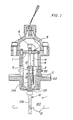
- Figure 1 shows a microbend sensor used to sense the passage of vortices 21 in a fluid flow 100 on one side of a sensor housing 9 for the sensor, having a sensor housing flange 22 for isolating the sensor from the fluid flow 100.
- a sensor beam 10 has an upper portion 10a which extends upwardly into the sensor housing 9, and a lower portion 10 b which extends from the sensor housing flange 22 into the fluid flow 100.
- a pressure boundary means for example in the form of a flexible diaphragm 23 is connected to the sensor housing 9 and isolates a sensor space in the sensor housing 9 from the fluid flow 100 on the opposite side of the flange 22.
- a sensor assembly is mounted in the sensor space of the sensor housing 9. It comprises a mounting bracket 1 which has an upper flange portion that is fixed to the housing 9.
- the mounting bracket 1 has a part 1a that forms a frame for holding a sensor assembly.
- the sensor assembly comprises a first microbend jaw 2 that is attached to the frame 1a by resilient means such as a spring.
- a second microbend jaw 3 is held to the first jaw 2 with an optical fibre 5 located between the first and second jaws 2 and 3.
- the optical fibre 5, which may be in the form of a cable, terminates in connectors 6 which are attached to the mounting bracket 1.
- the connectors 6 are used for coupling the optical fibre 5 to circuitry (not shown) for analyzing light passing through the optical fibre 5.
- the optical fibre 5 is supported and positioned by the mounting bracket 1.
- the second jaw 3 is held fast to the upper portion 10a of the sensor beam 10 by bolts 13.
- the second jaw 3 When assembled, the second jaw 3 is rigidly held with respect to the sensor beam 10 which serves as a mechanical input to the sensor assembly.
- the sensor beam 10 When the vortices 21 in the fluid flow 100 pass the lower portion 10 b of the sensor beam 10, the sensor beam 10 is caused to pivot about the diaphragm 23. This pivotal movement is transferred to the second jaw 3 which, in co-operation with the first jaw 2, bends and releases the optical fibre 5 and thereby modulates light passing therethrough. These modulations can be detected and measured and correspond to the passage of the vortices 21.
- An adjustment screw 32 is threaded into the sensor housing 9 and can be used to adjust the position of the first jaw 2 to provide calibration adjustment for the sensor assembly.
- Figure 2 is a side elevation of the first and second jaws 2 and 3 with the optical fibre 5 therebetween.
- the corrugations are in simple zig-zag form with the projections of the corrugations of one jaw opposing valleys of the corrugations of the other jaw. If the jaws 2 and 3 of Figure 2 are overloaded when pushed in a direction towards each other, they may bend the optical fibre 5 into a bend with a smaller radius than the fibre can accommodate. This overstresses the optical fibre and leads to excessive wear or damage.
- Figure 3 shows an arrangement where jaws 2 ⁇ and 3 ⁇ are provided with corner projections 2a and 3a. As shown in Figure 4, when the jaws 2 ⁇ , 3 ⁇ are loaded they 2 ⁇ , 3 ⁇ can move together only to the extent permitted by the corner projections 2a, 3a. This limits the amount of bending of the optical fibre 5.
- the jaws 2 ⁇ and 3 ⁇ with their corner projections 2a and 3a are difficult and complicated to manufacture and and require close tolerances to avoid overbending of the optical fibre 5.
- Each jaw of jaws 2 ⁇ , 3 ⁇ has a corrugated portion made up of flat areas 2 b , 3 b which are separated by projections 2 c , 3 c .
- Each projection 2 c , 3 c is positioned to oppose one of the flat areas 2 b , 3 b of the opposing jaw and the optical fibre 5 is engaged by the projections 2 c , 3 c .
- Figure 5 shows the normal modulating position, with the jaws 2 ⁇ , 3 ⁇ being movable together by a maximum amount limited to the height of the projections 2 c or 3 c .
- Figure 6 shows an overload condition where the projections 3 c of the jaw 3 ⁇ , and the projections 2 c of the jaw 2 ⁇ have pressed bends in the optical fibre 5 up against flat areas 2 b and 3 b respectively.
- each section of the optical fibre 5 can be bent only to a selected minimum radius, which is determined by the height of the projections 2 c , 3 c , the spacing between the projections 2 c , 3 c , that is to say the period of the corrugations, and the diameter of the optical fibre 5.
- Each flat area 2 b , 3 b lies in a single plane in the respective jaw, which plane extends perpendicularly to the relative displacement direction of the jaws 2 ⁇ , 3 ⁇ .
- the flat surfaces between the projections may be replaced by slightly concave surfaces. This can produce line contact between the optical fibre and the jaw in order to lower the stresses on the optical fibre during overload conditions.
- the surfaces of the jaws may also be made of a relatively soft material, perhaps even an elastic material, compared to the remainder of the jaw, in order to reduce the contact stresses as well as to reduce stresses due to impact.
- the optical fibre itself may be coated, for example with aluminum. Another possibility would be to use flat surfaces on only one of the jaws thus enabling the second jaw to be made less expensively.
Landscapes
- Physics & Mathematics (AREA)
- General Physics & Mathematics (AREA)
- Optics & Photonics (AREA)
- Fluid Mechanics (AREA)
- Light Guides In General And Applications Therefor (AREA)
- Investigating Or Analysing Materials By Optical Means (AREA)
- Measuring Volume Flow (AREA)
- Optical Transform (AREA)
Abstract
Description
- The invention relates to a jaw arrangement for a microbend sensor comprising a pair of jaws each having a facing corrugated surface for holding an optical fibre therebetween and being movable with respect to one another to bend the optical fibre to modulate light passing through the optical fibre.
- Optical fibres or cables can be used to convey light between a light source and a light detector. It has been found that light in an optical fibre can be modulated by bending or otherwise distorting the fibre; this produces a modulated signal which can be picked up and processed by the light detector.
- In a previously proposed microbend sensor, for example of the kind used in a vortex shedding flowmeter, a sensor beam extends into a flow of fluid the flow rate of which is to be measured. By positioning a bluff or obstruction in the flowing fluid, vortices can be formed by fluid passing over and being shed from the bluff. The vortices move the sensor beam as they pass it. The frequency of the passage of the vortices can be used as a measurement of the flow rate.
- In a microbend sensor, the sensor beam has an end which is mechanically connected to one corrugated jaw of a two jaw arrangement. The other corrugated jaw is fixed in a housing of the sensor and an optical fibre is held between the corrugated jaws. The movement of the sensor beam causes squeezing and releasing of the optical fibre. Light passing through the optical fibre is thus modulated at a frequency corresponding to the passage of vortices in the fluid flow. In such microbend sensors, care should be taken to avoid overstressing of the optical fibre because this can reduce the life thereof. The optical fibre can be overstressed not only during the sensing operation, but also during a calibration step where the jaws are moved together by a determined amount in a calibration step. The jaws can inadvertently be pushed too closely together thereby damaging the optical fibre.
- According to the invention there is provided a jaw arrangement for a microbend sensor comprising:
a pair of jaws each having a facing corrugated surface for holding an optical fibre therebetween and being movable with respect to each other to bend the optical fibre to modulate light passing through the optical fibre, characterised in that;
each corrugated surface includes a plurality of generally flat areas, disposed in a common plane extending in a direction which is substantially perpendicular to the direction of relative movement of the jaws, and a plurality of projections extending from the generally flat surfaces in the direction of relative movement of the jaws;
the projections alternate with the flat areas;
the projections of one of the jaws oppose the generally flat areas of the other of the jaws; and
the jaws are movable together under an overload condition to cause the projections of one of the jaws to bend an optical fibre placed between the jaws against the flat areas of the other of the jaws. - Such a configuration for the jaws of a microbend sensor can accommodate overloads without adversely effecting an optical fibre held between the jaws. Thus when exposed to an overload condition pressing the jaws together, the projections press portions of the optical fibre engaged thereby against the opposed flat surfaces of the other jaw. This evenly distributes the load across the optical fibre and helps to avoid damage to the optical fibre.
- The length of each projection in the direction of relative movement between the jaws is selected to be equal to a maximum allowable deflection in the microbend sensor. This is determined by several factors including for example, the allowable stresses on the optical fibre. Once each portion of the fibre has been bent into contact with the flat areas of one of the jaws, no further bending is possible. In this way the optical fibre will not be overstressed.
- During normal operation, light passing through an optical fibre is modulated by the local bending of the optical fibre by each of the projections on the jaws. This bending produces a light loss in the optical fibre which can be detected as a signal corresponding to movement of one of the jaws with respect to the other of the jaws.
- The invention is diagrammatically illustrated by way of example in the accompanying drawings; in which:-
- Figure 1 is a sectional elevation of a microbend sensor in a vortex shedding flowmeter using corrugated jaws of known kind;
- Figure 2 is a side elevation of corrugated jaws for a microbend sensor of the kind shown in Figure 1 and having no overload protection;
- Figure 3 is a perspective view with portions cut away of a jaw arrangement in a microbend sensor with some form of overstress protection;
- Figure 4 is a side elevation of the jaw arrangement shown in Figure 3, showing an overload condition;
- Figure 5 is a side elevation of a jaw arrangement for a microbend sensor according to the invention; and
- Figure 6 is a view similar to Figure 5 showing the jaw arrangement of Figure 5 in an overload condition under which condition the optical fibre is still not overstressed.
- Figure 1 shows a microbend sensor used to sense the passage of
vortices 21 in afluid flow 100 on one side of asensor housing 9 for the sensor, having asensor housing flange 22 for isolating the sensor from thefluid flow 100. - A
sensor beam 10 has anupper portion 10ª which extends upwardly into thesensor housing 9, and a lower portion 10b which extends from thesensor housing flange 22 into thefluid flow 100. A pressure boundary means, for example in the form of aflexible diaphragm 23 is connected to thesensor housing 9 and isolates a sensor space in thesensor housing 9 from thefluid flow 100 on the opposite side of theflange 22. - A sensor assembly is mounted in the sensor space of the
sensor housing 9. It comprises a mounting bracket 1 which has an upper flange portion that is fixed to thehousing 9. - The mounting bracket 1 has a part 1ª that forms a frame for holding a sensor assembly. the sensor assembly comprises a
first microbend jaw 2 that is attached to the frame 1ª by resilient means such as a spring. Asecond microbend jaw 3 is held to thefirst jaw 2 with anoptical fibre 5 located between the first andsecond jaws optical fibre 5, which may be in the form of a cable, terminates inconnectors 6 which are attached to the mounting bracket 1. Theconnectors 6 are used for coupling theoptical fibre 5 to circuitry (not shown) for analyzing light passing through theoptical fibre 5. Theoptical fibre 5 is supported and positioned by the mounting bracket 1. Thesecond jaw 3 is held fast to theupper portion 10ª of thesensor beam 10 bybolts 13. - When assembled, the
second jaw 3 is rigidly held with respect to thesensor beam 10 which serves as a mechanical input to the sensor assembly. - When the
vortices 21 in thefluid flow 100 pass the lower portion 10b of thesensor beam 10, thesensor beam 10 is caused to pivot about thediaphragm 23. This pivotal movement is transferred to thesecond jaw 3 which, in co-operation with thefirst jaw 2, bends and releases theoptical fibre 5 and thereby modulates light passing therethrough. These modulations can be detected and measured and correspond to the passage of thevortices 21. - An
adjustment screw 32 is threaded into thesensor housing 9 and can be used to adjust the position of thefirst jaw 2 to provide calibration adjustment for the sensor assembly. - Figure 2 is a side elevation of the first and
second jaws optical fibre 5 therebetween. The corrugations are in simple zig-zag form with the projections of the corrugations of one jaw opposing valleys of the corrugations of the other jaw. If thejaws optical fibre 5 into a bend with a smaller radius than the fibre can accommodate. This overstresses the optical fibre and leads to excessive wear or damage. - Figure 3 shows an arrangement where jaws 2ʹ and 3ʹ are provided with
corner projections corner projections optical fibre 5. - The jaws 2ʹ and 3ʹ with their
corner projections optical fibre 5. - An embodiment of jaws according to the invention is shown in Figures 5 and 6. Each jaw of jaws 2ʺ, 3ʺ has a corrugated portion made up of
flat areas projections projection flat areas optical fibre 5 is engaged by theprojections - Figure 5 shows the normal modulating position, with the jaws 2ʺ, 3ʺ being movable together by a maximum amount limited to the height of the
projections - Figure 6 shows an overload condition where the
projections 3c of the jaw 3ʺ, and theprojections 2c of the jaw 2ʺ have pressed bends in theoptical fibre 5 up againstflat areas optical fibre 5 can be bent only to a selected minimum radius, which is determined by the height of theprojections projections optical fibre 5. - Each
flat area - Different corrugation patterns can also be used for the jaws. For example, the flat surfaces between the projections may be replaced by slightly concave surfaces. This can produce line contact between the optical fibre and the jaw in order to lower the stresses on the optical fibre during overload conditions. The surfaces of the jaws may also be made of a relatively soft material, perhaps even an elastic material, compared to the remainder of the jaw, in order to reduce the contact stresses as well as to reduce stresses due to impact. For the same reason the optical fibre itself may be coated, for example with aluminum. Another possibility would be to use flat surfaces on only one of the jaws thus enabling the second jaw to be made less expensively.
Claims (5)
each corrugated surface includes a plurality of generally flat areas (2b, 3b), disposed in a common plane extending in a direction which is substantially perpendicular to the direction of relative movement of the jaws, and a plurality of projections (2c, 3c) extending from the generally flat surfaces in the direction of relative movement of the jaws (2ʺ, 3ʺ);
the projections (2c, 3c) alternate with the flat areas (2b, 3b);
the projections (2c, 3c) of one of the jaws (2ʺ, 3ʺ) oppose the generally flat areas (2b, 3b) of the other of the jaws (2ʺ, 3ʺ); and
the jaws (2ʺ, 3ʺ) are movable together under an overload condition to cause the projections (2c, 3c) of one of the jaws (2ʺ, 3ʺ) to bend an optical fibre (5) placed between the jaws against the flat areas (2b, 3b) of the other of the jaws (2ʺ, 3ʺ).
Applications Claiming Priority (2)
| Application Number | Priority Date | Filing Date | Title |
|---|---|---|---|
| US82541486A | 1986-02-03 | 1986-02-03 | |
| US825414 | 1986-02-03 |
Publications (2)
| Publication Number | Publication Date |
|---|---|
| EP0240100A1 true EP0240100A1 (en) | 1987-10-07 |
| EP0240100B1 EP0240100B1 (en) | 1990-10-24 |
Family
ID=25243964
Family Applications (1)
| Application Number | Title | Priority Date | Filing Date |
|---|---|---|---|
| EP19870300384 Expired - Lifetime EP0240100B1 (en) | 1986-02-03 | 1987-01-16 | A jaw arrangement for a microbend sensor |
Country Status (11)
| Country | Link |
|---|---|
| EP (1) | EP0240100B1 (en) |
| JP (1) | JPS62190428A (en) |
| KR (1) | KR870008200A (en) |
| AU (1) | AU596376B2 (en) |
| BR (1) | BR8700138A (en) |
| CA (1) | CA1261028A (en) |
| DE (1) | DE3765674D1 (en) |
| ES (1) | ES2002562A6 (en) |
| HK (1) | HK35892A (en) |
| IN (1) | IN165010B (en) |
| SG (1) | SG106591G (en) |
Cited By (8)
| Publication number | Priority date | Publication date | Assignee | Title |
|---|---|---|---|---|
| GB2226128A (en) * | 1988-12-07 | 1990-06-20 | Bicc Plc | Optical fibre monitoring |
| EP0393956A3 (en) * | 1989-04-19 | 1991-05-02 | Bestquint Limited | Optical fibre sensors |
| US5067786A (en) * | 1989-12-21 | 1991-11-26 | Bicc Public Limited Company | Optical fibre monitoring |
| EP0503985A1 (en) * | 1991-03-15 | 1992-09-16 | Faiveley Transport | Force sensor and apparatus for sensing the current of a catenary line from a motor by using this sensor |
| EP0525717A1 (en) * | 1991-08-02 | 1993-02-03 | Alcatel Cable | Fiber optical humidity sensor |
| EP0841545A1 (en) * | 1996-11-08 | 1998-05-13 | Endress + Hauser Flowtec AG | Vortex flow sensor |
| EP1571433A3 (en) * | 2004-03-05 | 2006-05-10 | Denso Corporation | Load sensor mounting device with sensor-protective structure |
| DE102013105363A1 (en) * | 2013-05-24 | 2014-11-27 | Endress + Hauser Flowtec Ag | Vortex flow sensor and vortex flow sensor for measuring the flow rate of a fluid |
Families Citing this family (2)
| Publication number | Priority date | Publication date | Assignee | Title |
|---|---|---|---|---|
| CA1299389C (en) * | 1986-10-30 | 1992-04-28 | John W. Berthold | Microbend fiber optic strain gauge |
| CN110702020A (en) * | 2019-10-15 | 2020-01-17 | 天津大学 | Optical fiber sensor based on optical time domain reflectometry and method of using the same |
Citations (2)
| Publication number | Priority date | Publication date | Assignee | Title |
|---|---|---|---|---|
| US4477725A (en) * | 1981-08-27 | 1984-10-16 | Trw Inc. | Microbending of optical fibers for remote force measurement |
| US4552026A (en) * | 1984-10-22 | 1985-11-12 | The Babcock & Wilcox Company | Sensor for a vortex shedding flowmeter |
Family Cites Families (2)
| Publication number | Priority date | Publication date | Assignee | Title |
|---|---|---|---|---|
| EP0027540A3 (en) * | 1979-09-11 | 1981-10-07 | Hydroacoustics Inc. | Optical sensor and transducer array system |
| US4313192A (en) * | 1979-09-11 | 1982-01-26 | Hydroacoustics, Inc. | Optical transducer array system |
-
1986
- 1986-09-17 IN IN689/CAL/86A patent/IN165010B/en unknown
- 1986-09-25 AU AU63178/86A patent/AU596376B2/en not_active Ceased
- 1986-09-27 KR KR1019860008115A patent/KR870008200A/en not_active Ceased
- 1986-10-29 CA CA000521725A patent/CA1261028A/en not_active Expired
-
1987
- 1987-01-15 BR BR8700138A patent/BR8700138A/en unknown
- 1987-01-16 DE DE8787300384T patent/DE3765674D1/en not_active Expired - Fee Related
- 1987-01-16 EP EP19870300384 patent/EP0240100B1/en not_active Expired - Lifetime
- 1987-01-20 ES ES8700132A patent/ES2002562A6/en not_active Expired - Fee Related
- 1987-01-28 JP JP62016325A patent/JPS62190428A/en active Pending
-
1991
- 1991-12-16 SG SG106591A patent/SG106591G/en unknown
-
1992
- 1992-05-21 HK HK358/92A patent/HK35892A/en unknown
Patent Citations (2)
| Publication number | Priority date | Publication date | Assignee | Title |
|---|---|---|---|---|
| US4477725A (en) * | 1981-08-27 | 1984-10-16 | Trw Inc. | Microbending of optical fibers for remote force measurement |
| US4552026A (en) * | 1984-10-22 | 1985-11-12 | The Babcock & Wilcox Company | Sensor for a vortex shedding flowmeter |
Cited By (17)
| Publication number | Priority date | Publication date | Assignee | Title |
|---|---|---|---|---|
| EP0548053A3 (en) * | 1988-12-07 | 1994-05-25 | Bicc Plc | Optical fibre monitoring by micro- and macro-bending portions of the optical fibre |
| EP0372689A3 (en) * | 1988-12-07 | 1990-12-12 | Bicc Public Limited Company | Optical fibre monitoring |
| GB2226128B (en) * | 1988-12-07 | 1992-08-12 | Bicc Plc | Optical fibre monitoring |
| GB2226128A (en) * | 1988-12-07 | 1990-06-20 | Bicc Plc | Optical fibre monitoring |
| EP0393956A3 (en) * | 1989-04-19 | 1991-05-02 | Bestquint Limited | Optical fibre sensors |
| US5084615A (en) * | 1989-04-19 | 1992-01-28 | Bestquint Limited | Optical fibre sensors with strip portions having a series of transverse ridges |
| US5067786A (en) * | 1989-12-21 | 1991-11-26 | Bicc Public Limited Company | Optical fibre monitoring |
| EP0503985A1 (en) * | 1991-03-15 | 1992-09-16 | Faiveley Transport | Force sensor and apparatus for sensing the current of a catenary line from a motor by using this sensor |
| FR2674020A1 (en) * | 1991-03-15 | 1992-09-18 | Faiveley Transport | FORCE SENSOR AND APPARATUS FOR CAPTURING THE CURRENT OF A CATENARY LINE FROM A MOTOR USING THE SAME. |
| EP0525717A1 (en) * | 1991-08-02 | 1993-02-03 | Alcatel Cable | Fiber optical humidity sensor |
| US5243670A (en) * | 1991-08-02 | 1993-09-07 | Alcatel Cable | Optical fiber moisture sensor |
| FR2680004A1 (en) * | 1991-08-02 | 1993-02-05 | Alcatel Cable | FIBER OPTIC MOISTURE SENSOR. |
| EP0841545A1 (en) * | 1996-11-08 | 1998-05-13 | Endress + Hauser Flowtec AG | Vortex flow sensor |
| US6003384A (en) * | 1996-11-08 | 1999-12-21 | Endress +Hauser Flowtec Ag | Vortex flow sensor with a capacitive sensing element |
| EP1571433A3 (en) * | 2004-03-05 | 2006-05-10 | Denso Corporation | Load sensor mounting device with sensor-protective structure |
| DE102013105363A1 (en) * | 2013-05-24 | 2014-11-27 | Endress + Hauser Flowtec Ag | Vortex flow sensor and vortex flow sensor for measuring the flow rate of a fluid |
| US9719819B2 (en) | 2013-05-24 | 2017-08-01 | Endress + Hauser Flowtec Ag | Vortex flow sensor for a vortex flow transducer having a flange shaped support device for supporting a membrane in a housing |
Also Published As
| Publication number | Publication date |
|---|---|
| EP0240100B1 (en) | 1990-10-24 |
| DE3765674D1 (en) | 1990-11-29 |
| HK35892A (en) | 1992-05-29 |
| SG106591G (en) | 1992-02-14 |
| JPS62190428A (en) | 1987-08-20 |
| IN165010B (en) | 1989-07-29 |
| KR870008200A (en) | 1987-09-25 |
| CA1261028A (en) | 1989-09-26 |
| ES2002562A6 (en) | 1991-11-01 |
| AU6317886A (en) | 1987-08-06 |
| AU596376B2 (en) | 1990-05-03 |
| BR8700138A (en) | 1988-08-23 |
Similar Documents
| Publication | Publication Date | Title |
|---|---|---|
| EP0240100B1 (en) | A jaw arrangement for a microbend sensor | |
| US4871908A (en) | Overload protection for fiber optic microbend sensor | |
| US4449210A (en) | Fiber optic hydrophone transducers | |
| US4436995A (en) | Fiber optics transducers for sensing parameter magnitude | |
| US4477725A (en) | Microbending of optical fibers for remote force measurement | |
| US4724316A (en) | Temperature independent fiber optic sensor | |
| KR100193932B1 (en) | Devices for measuring the force applied on the terminals during crimping | |
| KR20020073479A (en) | Flexible fiber optic microbend device, sensors, and method of use | |
| US4472628A (en) | Fiber optics transducers for sensing parameter magnitude | |
| CA2338409A1 (en) | Patch type optical fiber sensor | |
| US4822135A (en) | Optical wave guide band edge sensor and method | |
| WO2001061386A2 (en) | Thermal compensated compact bragg grating filter | |
| GB2125161A (en) | Optical fibre sensors | |
| JP3628331B2 (en) | Extensometer | |
| US6341526B1 (en) | Micromachined diffractive pressure sensor system | |
| CA1170197A (en) | Constant tension device for filter bag | |
| WO1998008045A1 (en) | Extensometer structure | |
| EP0082615A1 (en) | Opto-mechanical ripple transducer with adjustable sensitivity | |
| US4380935A (en) | External sensing vortex flowmeter | |
| EP0531017B1 (en) | Sensor | |
| US4199980A (en) | Folded beam structure utilization methods and apparatus | |
| RU2019790C1 (en) | Device to register linear deformations | |
| KR100414857B1 (en) | Pressure sensor using optical fiber | |
| US6718078B2 (en) | High sensitivity fiber optic rotation sensor | |
| EP0699897A1 (en) | Fluid flow meter |
Legal Events
| Date | Code | Title | Description |
|---|---|---|---|
| PUAI | Public reference made under article 153(3) epc to a published international application that has entered the european phase |
Free format text: ORIGINAL CODE: 0009012 |
|
| AK | Designated contracting states |
Kind code of ref document: A1 Designated state(s): DE FR GB IT SE |
|
| 17P | Request for examination filed |
Effective date: 19880323 |
|
| 17Q | First examination report despatched |
Effective date: 19890811 |
|
| GRAA | (expected) grant |
Free format text: ORIGINAL CODE: 0009210 |
|
| RAP1 | Party data changed (applicant data changed or rights of an application transferred) |
Owner name: INTERNATIONAL CONTROL AUTOMATION FINANCE S.A. |
|
| AK | Designated contracting states |
Kind code of ref document: B1 Designated state(s): DE FR GB IT SE |
|
| ITF | It: translation for a ep patent filed | ||
| REF | Corresponds to: |
Ref document number: 3765674 Country of ref document: DE Date of ref document: 19901129 |
|
| ET | Fr: translation filed | ||
| PLBE | No opposition filed within time limit |
Free format text: ORIGINAL CODE: 0009261 |
|
| STAA | Information on the status of an ep patent application or granted ep patent |
Free format text: STATUS: NO OPPOSITION FILED WITHIN TIME LIMIT |
|
| 26N | No opposition filed | ||
| ITTA | It: last paid annual fee | ||
| PGFP | Annual fee paid to national office [announced via postgrant information from national office to epo] |
Ref country code: FR Payment date: 19921210 Year of fee payment: 7 |
|
| PGFP | Annual fee paid to national office [announced via postgrant information from national office to epo] |
Ref country code: SE Payment date: 19921211 Year of fee payment: 7 Ref country code: DE Payment date: 19921211 Year of fee payment: 7 |
|
| PGFP | Annual fee paid to national office [announced via postgrant information from national office to epo] |
Ref country code: GB Payment date: 19921231 Year of fee payment: 7 |
|
| PG25 | Lapsed in a contracting state [announced via postgrant information from national office to epo] |
Ref country code: GB Effective date: 19940116 |
|
| PG25 | Lapsed in a contracting state [announced via postgrant information from national office to epo] |
Ref country code: SE Effective date: 19940117 |
|
| GBPC | Gb: european patent ceased through non-payment of renewal fee |
Effective date: 19940116 |
|
| PG25 | Lapsed in a contracting state [announced via postgrant information from national office to epo] |
Ref country code: FR Effective date: 19940930 |
|
| PG25 | Lapsed in a contracting state [announced via postgrant information from national office to epo] |
Ref country code: DE Effective date: 19941001 |
|
| REG | Reference to a national code |
Ref country code: FR Ref legal event code: ST |
|
| EUG | Se: european patent has lapsed |
Ref document number: 87300384.2 Effective date: 19940810 |
|
| PG25 | Lapsed in a contracting state [announced via postgrant information from national office to epo] |
Ref country code: IT Free format text: LAPSE BECAUSE OF NON-PAYMENT OF DUE FEES Effective date: 20050116 |