EP0239877B1 - Method for producing composite structures with a polyurethane interior, and the composite structure obtained - Google Patents
Method for producing composite structures with a polyurethane interior, and the composite structure obtained Download PDFInfo
- Publication number
- EP0239877B1 EP0239877B1 EP87103935A EP87103935A EP0239877B1 EP 0239877 B1 EP0239877 B1 EP 0239877B1 EP 87103935 A EP87103935 A EP 87103935A EP 87103935 A EP87103935 A EP 87103935A EP 0239877 B1 EP0239877 B1 EP 0239877B1
- Authority
- EP
- European Patent Office
- Prior art keywords
- polymethylmethacrylate
- polyurethane
- layer
- vacuum
- impact resistant
- Prior art date
- Legal status (The legal status is an assumption and is not a legal conclusion. Google has not performed a legal analysis and makes no representation as to the accuracy of the status listed.)
- Expired - Lifetime
Links
- 229920002635 polyurethane Polymers 0.000 title claims abstract description 40
- 239000004814 polyurethane Substances 0.000 title claims abstract description 40
- 239000002131 composite material Substances 0.000 title claims abstract description 11
- 238000004519 manufacturing process Methods 0.000 title claims abstract description 7
- 239000004926 polymethyl methacrylate Substances 0.000 claims abstract description 42
- 229920003229 poly(methyl methacrylate) Polymers 0.000 claims abstract description 41
- 238000010438 heat treatment Methods 0.000 claims abstract description 8
- 238000005755 formation reaction Methods 0.000 claims abstract 3
- 239000000203 mixture Substances 0.000 claims description 25
- 229920005862 polyol Polymers 0.000 claims description 20
- 150000003077 polyols Chemical class 0.000 claims description 20
- 238000000034 method Methods 0.000 claims description 16
- 238000006243 chemical reaction Methods 0.000 claims description 10
- 239000012948 isocyanate Substances 0.000 claims description 10
- 150000002513 isocyanates Chemical class 0.000 claims description 10
- 238000007666 vacuum forming Methods 0.000 claims description 7
- 238000003466 welding Methods 0.000 claims description 5
- PEDCQBHIVMGVHV-UHFFFAOYSA-N Glycerine Chemical compound OCC(O)CO PEDCQBHIVMGVHV-UHFFFAOYSA-N 0.000 claims description 4
- 239000003054 catalyst Substances 0.000 claims description 4
- 150000001875 compounds Chemical class 0.000 claims description 4
- 229920000642 polymer Polymers 0.000 claims description 4
- 239000003795 chemical substances by application Substances 0.000 claims description 3
- 150000003512 tertiary amines Chemical class 0.000 claims description 3
- FBPFZTCFMRRESA-FSIIMWSLSA-N D-Glucitol Natural products OC[C@H](O)[C@H](O)[C@@H](O)[C@H](O)CO FBPFZTCFMRRESA-FSIIMWSLSA-N 0.000 claims description 2
- FBPFZTCFMRRESA-JGWLITMVSA-N D-glucitol Chemical compound OC[C@H](O)[C@@H](O)[C@H](O)[C@H](O)CO FBPFZTCFMRRESA-JGWLITMVSA-N 0.000 claims description 2
- VGGSQFUCUMXWEO-UHFFFAOYSA-N Ethene Chemical compound C=C VGGSQFUCUMXWEO-UHFFFAOYSA-N 0.000 claims description 2
- 239000005977 Ethylene Substances 0.000 claims description 2
- CZMRCDWAGMRECN-UGDNZRGBSA-N Sucrose Chemical compound O[C@H]1[C@H](O)[C@@H](CO)O[C@@]1(CO)O[C@@H]1[C@H](O)[C@@H](O)[C@H](O)[C@@H](CO)O1 CZMRCDWAGMRECN-UGDNZRGBSA-N 0.000 claims description 2
- 229930006000 Sucrose Natural products 0.000 claims description 2
- 150000001298 alcohols Chemical class 0.000 claims description 2
- 125000002947 alkylene group Chemical group 0.000 claims description 2
- 235000013681 dietary sucrose Nutrition 0.000 claims description 2
- 235000011187 glycerol Nutrition 0.000 claims description 2
- 125000002887 hydroxy group Chemical group [H]O* 0.000 claims description 2
- QQONPFPTGQHPMA-UHFFFAOYSA-N propylene Natural products CC=C QQONPFPTGQHPMA-UHFFFAOYSA-N 0.000 claims description 2
- 125000004805 propylene group Chemical group [H]C([H])([H])C([H])([*:1])C([H])([H])[*:2] 0.000 claims description 2
- 235000010356 sorbitol Nutrition 0.000 claims description 2
- 239000000600 sorbitol Substances 0.000 claims description 2
- 229960004793 sucrose Drugs 0.000 claims description 2
- KSBAEPSJVUENNK-UHFFFAOYSA-L tin(ii) 2-ethylhexanoate Chemical compound [Sn+2].CCCCC(CC)C([O-])=O.CCCCC(CC)C([O-])=O KSBAEPSJVUENNK-UHFFFAOYSA-L 0.000 claims description 2
- UPMLOUAZCHDJJD-UHFFFAOYSA-N 4,4'-Diphenylmethane Diisocyanate Chemical compound C1=CC(N=C=O)=CC=C1CC1=CC=C(N=C=O)C=C1 UPMLOUAZCHDJJD-UHFFFAOYSA-N 0.000 claims 1
- XLYOFNOQVPJJNP-UHFFFAOYSA-N water Substances O XLYOFNOQVPJJNP-UHFFFAOYSA-N 0.000 description 13
- 238000001816 cooling Methods 0.000 description 6
- 239000004005 microsphere Substances 0.000 description 4
- WSFSSNUMVMOOMR-UHFFFAOYSA-N Formaldehyde Chemical compound O=C WSFSSNUMVMOOMR-UHFFFAOYSA-N 0.000 description 3
- 238000005520 cutting process Methods 0.000 description 3
- 239000000945 filler Substances 0.000 description 3
- 239000011521 glass Substances 0.000 description 3
- 239000000463 material Substances 0.000 description 3
- 238000009966 trimming Methods 0.000 description 3
- PAYRUJLWNCNPSJ-UHFFFAOYSA-N Aniline Chemical compound NC1=CC=CC=C1 PAYRUJLWNCNPSJ-UHFFFAOYSA-N 0.000 description 2
- 230000000694 effects Effects 0.000 description 2
- 230000002093 peripheral effect Effects 0.000 description 2
- 229920002994 synthetic fiber Polymers 0.000 description 2
- ZXUJWPHOPHHZLR-UHFFFAOYSA-N 1,1,1-trichloro-2-fluoroethane Chemical compound FCC(Cl)(Cl)Cl ZXUJWPHOPHHZLR-UHFFFAOYSA-N 0.000 description 1
- BVKZGUZCCUSVTD-UHFFFAOYSA-L Carbonate Chemical compound [O-]C([O-])=O BVKZGUZCCUSVTD-UHFFFAOYSA-L 0.000 description 1
- VEXZGXHMUGYJMC-UHFFFAOYSA-M Chloride anion Chemical compound [Cl-] VEXZGXHMUGYJMC-UHFFFAOYSA-M 0.000 description 1
- LFQSCWFLJHTTHZ-UHFFFAOYSA-N Ethanol Chemical compound CCO LFQSCWFLJHTTHZ-UHFFFAOYSA-N 0.000 description 1
- 229920005482 Oroglas® Polymers 0.000 description 1
- YGYAWVDWMABLBF-UHFFFAOYSA-N Phosgene Chemical compound ClC(Cl)=O YGYAWVDWMABLBF-UHFFFAOYSA-N 0.000 description 1
- 125000001931 aliphatic group Chemical group 0.000 description 1
- -1 ammonium silicates Chemical class 0.000 description 1
- 150000004649 carbonic acid derivatives Chemical class 0.000 description 1
- 238000007796 conventional method Methods 0.000 description 1
- 230000005611 electricity Effects 0.000 description 1
- 239000012530 fluid Substances 0.000 description 1
- 230000005484 gravity Effects 0.000 description 1
- 150000008282 halocarbons Chemical class 0.000 description 1
- 125000004435 hydrogen atom Chemical group [H]* 0.000 description 1
- 239000002184 metal Substances 0.000 description 1
- 229920003023 plastic Polymers 0.000 description 1
- 239000004033 plastic Substances 0.000 description 1
- 230000002787 reinforcement Effects 0.000 description 1
- 230000000717 retained effect Effects 0.000 description 1
- 238000000926 separation method Methods 0.000 description 1
- 238000010008 shearing Methods 0.000 description 1
- 229920002545 silicone oil Polymers 0.000 description 1
- 239000002904 solvent Substances 0.000 description 1
- 239000000126 substance Substances 0.000 description 1
- NCEXYHBECQHGNR-QZQOTICOSA-N sulfasalazine Chemical compound C1=C(O)C(C(=O)O)=CC(\N=N\C=2C=CC(=CC=2)S(=O)(=O)NC=2N=CC=CC=2)=C1 NCEXYHBECQHGNR-QZQOTICOSA-N 0.000 description 1
- 150000003467 sulfuric acid derivatives Chemical class 0.000 description 1
Images



Classifications
-
- B—PERFORMING OPERATIONS; TRANSPORTING
- B29—WORKING OF PLASTICS; WORKING OF SUBSTANCES IN A PLASTIC STATE IN GENERAL
- B29C—SHAPING OR JOINING OF PLASTICS; SHAPING OF MATERIAL IN A PLASTIC STATE, NOT OTHERWISE PROVIDED FOR; AFTER-TREATMENT OF THE SHAPED PRODUCTS, e.g. REPAIRING
- B29C39/00—Shaping by casting, i.e. introducing the moulding material into a mould or between confining surfaces without significant moulding pressure; Apparatus therefor
- B29C39/02—Shaping by casting, i.e. introducing the moulding material into a mould or between confining surfaces without significant moulding pressure; Apparatus therefor for making articles of definite length, i.e. discrete articles
- B29C39/12—Making multilayered or multicoloured articles
- B29C39/123—Making multilayered articles
- B29C39/126—Making multilayered articles by casting between two preformed layers, e.g. deformable layers
-
- B—PERFORMING OPERATIONS; TRANSPORTING
- B32—LAYERED PRODUCTS
- B32B—LAYERED PRODUCTS, i.e. PRODUCTS BUILT-UP OF STRATA OF FLAT OR NON-FLAT, e.g. CELLULAR OR HONEYCOMB, FORM
- B32B27/00—Layered products comprising a layer of synthetic resin
- B32B27/06—Layered products comprising a layer of synthetic resin as the main or only constituent of a layer, which is next to another layer of the same or of a different material
- B32B27/065—Layered products comprising a layer of synthetic resin as the main or only constituent of a layer, which is next to another layer of the same or of a different material of foam
-
- B—PERFORMING OPERATIONS; TRANSPORTING
- B29—WORKING OF PLASTICS; WORKING OF SUBSTANCES IN A PLASTIC STATE IN GENERAL
- B29C—SHAPING OR JOINING OF PLASTICS; SHAPING OF MATERIAL IN A PLASTIC STATE, NOT OTHERWISE PROVIDED FOR; AFTER-TREATMENT OF THE SHAPED PRODUCTS, e.g. REPAIRING
- B29C44/00—Shaping by internal pressure generated in the material, e.g. swelling or foaming ; Producing porous or cellular expanded plastics articles
- B29C44/02—Shaping by internal pressure generated in the material, e.g. swelling or foaming ; Producing porous or cellular expanded plastics articles for articles of definite length, i.e. discrete articles
- B29C44/12—Incorporating or moulding on preformed parts, e.g. inserts or reinforcements
- B29C44/14—Incorporating or moulding on preformed parts, e.g. inserts or reinforcements the preformed part being a lining
-
- B—PERFORMING OPERATIONS; TRANSPORTING
- B29—WORKING OF PLASTICS; WORKING OF SUBSTANCES IN A PLASTIC STATE IN GENERAL
- B29C—SHAPING OR JOINING OF PLASTICS; SHAPING OF MATERIAL IN A PLASTIC STATE, NOT OTHERWISE PROVIDED FOR; AFTER-TREATMENT OF THE SHAPED PRODUCTS, e.g. REPAIRING
- B29C51/00—Shaping by thermoforming, i.e. shaping sheets or sheet like preforms after heating, e.g. shaping sheets in matched moulds or by deep-drawing; Apparatus therefor
- B29C51/002—Shaping by thermoforming, i.e. shaping sheets or sheet like preforms after heating, e.g. shaping sheets in matched moulds or by deep-drawing; Apparatus therefor characterised by the choice of material
-
- B—PERFORMING OPERATIONS; TRANSPORTING
- B29—WORKING OF PLASTICS; WORKING OF SUBSTANCES IN A PLASTIC STATE IN GENERAL
- B29C—SHAPING OR JOINING OF PLASTICS; SHAPING OF MATERIAL IN A PLASTIC STATE, NOT OTHERWISE PROVIDED FOR; AFTER-TREATMENT OF THE SHAPED PRODUCTS, e.g. REPAIRING
- B29C70/00—Shaping composites, i.e. plastics material comprising reinforcements, fillers or preformed parts, e.g. inserts
- B29C70/58—Shaping composites, i.e. plastics material comprising reinforcements, fillers or preformed parts, e.g. inserts comprising fillers only, e.g. particles, powder, beads, flakes, spheres
- B29C70/66—Shaping composites, i.e. plastics material comprising reinforcements, fillers or preformed parts, e.g. inserts comprising fillers only, e.g. particles, powder, beads, flakes, spheres the filler comprising hollow constituents, e.g. syntactic foam
-
- B—PERFORMING OPERATIONS; TRANSPORTING
- B32—LAYERED PRODUCTS
- B32B—LAYERED PRODUCTS, i.e. PRODUCTS BUILT-UP OF STRATA OF FLAT OR NON-FLAT, e.g. CELLULAR OR HONEYCOMB, FORM
- B32B27/00—Layered products comprising a layer of synthetic resin
- B32B27/30—Layered products comprising a layer of synthetic resin comprising vinyl (co)polymers; comprising acrylic (co)polymers
- B32B27/308—Layered products comprising a layer of synthetic resin comprising vinyl (co)polymers; comprising acrylic (co)polymers comprising acrylic (co)polymers
-
- B—PERFORMING OPERATIONS; TRANSPORTING
- B32—LAYERED PRODUCTS
- B32B—LAYERED PRODUCTS, i.e. PRODUCTS BUILT-UP OF STRATA OF FLAT OR NON-FLAT, e.g. CELLULAR OR HONEYCOMB, FORM
- B32B27/00—Layered products comprising a layer of synthetic resin
- B32B27/40—Layered products comprising a layer of synthetic resin comprising polyurethanes
-
- B—PERFORMING OPERATIONS; TRANSPORTING
- B32—LAYERED PRODUCTS
- B32B—LAYERED PRODUCTS, i.e. PRODUCTS BUILT-UP OF STRATA OF FLAT OR NON-FLAT, e.g. CELLULAR OR HONEYCOMB, FORM
- B32B38/00—Ancillary operations in connection with laminating processes
- B32B38/0036—Heat treatment
-
- B—PERFORMING OPERATIONS; TRANSPORTING
- B32—LAYERED PRODUCTS
- B32B—LAYERED PRODUCTS, i.e. PRODUCTS BUILT-UP OF STRATA OF FLAT OR NON-FLAT, e.g. CELLULAR OR HONEYCOMB, FORM
- B32B38/00—Ancillary operations in connection with laminating processes
- B32B38/18—Handling of layers or the laminate
- B32B38/1858—Handling of layers or the laminate using vacuum
-
- B—PERFORMING OPERATIONS; TRANSPORTING
- B32—LAYERED PRODUCTS
- B32B—LAYERED PRODUCTS, i.e. PRODUCTS BUILT-UP OF STRATA OF FLAT OR NON-FLAT, e.g. CELLULAR OR HONEYCOMB, FORM
- B32B5/00—Layered products characterised by the non- homogeneity or physical structure, i.e. comprising a fibrous, filamentary, particulate or foam layer; Layered products characterised by having a layer differing constitutionally or physically in different parts
- B32B5/18—Layered products characterised by the non- homogeneity or physical structure, i.e. comprising a fibrous, filamentary, particulate or foam layer; Layered products characterised by having a layer differing constitutionally or physically in different parts characterised by features of a layer of foamed material
- B32B5/20—Layered products characterised by the non- homogeneity or physical structure, i.e. comprising a fibrous, filamentary, particulate or foam layer; Layered products characterised by having a layer differing constitutionally or physically in different parts characterised by features of a layer of foamed material foamed in situ
-
- B—PERFORMING OPERATIONS; TRANSPORTING
- B29—WORKING OF PLASTICS; WORKING OF SUBSTANCES IN A PLASTIC STATE IN GENERAL
- B29K—INDEXING SCHEME ASSOCIATED WITH SUBCLASSES B29B, B29C OR B29D, RELATING TO MOULDING MATERIALS OR TO MATERIALS FOR MOULDS, REINFORCEMENTS, FILLERS OR PREFORMED PARTS, e.g. INSERTS
- B29K2033/00—Use of polymers of unsaturated acids or derivatives thereof as moulding material
-
- B—PERFORMING OPERATIONS; TRANSPORTING
- B29—WORKING OF PLASTICS; WORKING OF SUBSTANCES IN A PLASTIC STATE IN GENERAL
- B29K—INDEXING SCHEME ASSOCIATED WITH SUBCLASSES B29B, B29C OR B29D, RELATING TO MOULDING MATERIALS OR TO MATERIALS FOR MOULDS, REINFORCEMENTS, FILLERS OR PREFORMED PARTS, e.g. INSERTS
- B29K2033/00—Use of polymers of unsaturated acids or derivatives thereof as moulding material
- B29K2033/04—Polymers of esters
- B29K2033/12—Polymers of methacrylic acid esters, e.g. PMMA, i.e. polymethylmethacrylate
-
- B—PERFORMING OPERATIONS; TRANSPORTING
- B29—WORKING OF PLASTICS; WORKING OF SUBSTANCES IN A PLASTIC STATE IN GENERAL
- B29K—INDEXING SCHEME ASSOCIATED WITH SUBCLASSES B29B, B29C OR B29D, RELATING TO MOULDING MATERIALS OR TO MATERIALS FOR MOULDS, REINFORCEMENTS, FILLERS OR PREFORMED PARTS, e.g. INSERTS
- B29K2075/00—Use of PU, i.e. polyureas or polyurethanes or derivatives thereof, as moulding material
-
- B—PERFORMING OPERATIONS; TRANSPORTING
- B29—WORKING OF PLASTICS; WORKING OF SUBSTANCES IN A PLASTIC STATE IN GENERAL
- B29K—INDEXING SCHEME ASSOCIATED WITH SUBCLASSES B29B, B29C OR B29D, RELATING TO MOULDING MATERIALS OR TO MATERIALS FOR MOULDS, REINFORCEMENTS, FILLERS OR PREFORMED PARTS, e.g. INSERTS
- B29K2105/00—Condition, form or state of moulded material or of the material to be shaped
- B29K2105/06—Condition, form or state of moulded material or of the material to be shaped containing reinforcements, fillers or inserts
- B29K2105/16—Fillers
- B29K2105/165—Hollow fillers, e.g. microballoons or expanded particles
-
- B—PERFORMING OPERATIONS; TRANSPORTING
- B29—WORKING OF PLASTICS; WORKING OF SUBSTANCES IN A PLASTIC STATE IN GENERAL
- B29L—INDEXING SCHEME ASSOCIATED WITH SUBCLASS B29C, RELATING TO PARTICULAR ARTICLES
- B29L2031/00—Other particular articles
- B29L2031/769—Sanitary equipment
- B29L2031/7694—Closets, toilets
-
- B—PERFORMING OPERATIONS; TRANSPORTING
- B32—LAYERED PRODUCTS
- B32B—LAYERED PRODUCTS, i.e. PRODUCTS BUILT-UP OF STRATA OF FLAT OR NON-FLAT, e.g. CELLULAR OR HONEYCOMB, FORM
- B32B2266/00—Composition of foam
- B32B2266/02—Organic
- B32B2266/0214—Materials belonging to B32B27/00
- B32B2266/0278—Polyurethane
-
- B—PERFORMING OPERATIONS; TRANSPORTING
- B32—LAYERED PRODUCTS
- B32B—LAYERED PRODUCTS, i.e. PRODUCTS BUILT-UP OF STRATA OF FLAT OR NON-FLAT, e.g. CELLULAR OR HONEYCOMB, FORM
- B32B2309/00—Parameters for the laminating or treatment process; Apparatus details
- B32B2309/60—In a particular environment
- B32B2309/68—Vacuum
Definitions
- This invention relates to a method for producing composite structures comprising at least two layers of synthetic materials, one of which is polyurethane.
- the invention also relates to the composite structures obtained by the method, for example panels or sheets, toilet seats and covers, paper holders, pen holders, furniture, furniture parts and other articles of industrial and domestic use.
- USA Patent 3,379,800 describes a method for producing toilet seats and covers comprising a layer (outer) of synthetic material and a layer (inner) of elastic expanded polyurethane.
- Polymethylmethacrylate is among the various materials proposed for the outer layer.
- the method consists of vacuum-forming a given shape from a polymethylmethacrylate sheet as so to form a cavity, feeding into this cavity a given quantity of expandable polyurethane mixture, covering this cavity with a polymethylmethacrylate sheet so as to close it and form a chamber, and then expanding the polyurethane mixture to fill this chamber.
- the modified polymethylmethacrylate used is of the impact resistant type, described for example in countertop patent 1045246 to which reference should be made for further details, and the different type of polyurethane is that defined as rigid compact or semiexpanded and therefore non-elastic, and the reaction of the polyurethane mixture for forming the rigid polyurethane layer in contact with the impact resistant polymethylmethacrylate layer is implemented under the action of heat while applying a vacuum to the impact resistant polymethylmethacrylate layer.
- the rigid compact or semiexpanded polyurethane is produced from a mixture, the reactive components of which comprises:
- the reaction between the two can be represented schematically as follows: ie when a polyfunctional isocyanate reacts with a polyfunctional alcohol (polyol), a complex structure polymer is obtained.
- Expanding agents water, halogenated hydrocarbons such as Freon (monofluoro-trichloroethane)
- fillers can be added tot he reactive polyurethane components, such as hollow glass microspheres of apparent density 180 g/1-680 g/i, carbonates, ammonium silicates, sulphates, reinforcement fibres or other substances well known in the polyurethane filler field.
- the usable quantities range from 5 to 60 parts by weight per 100 parts of polyol.
- catalysts such as stannous compounds (stannous octoate), tertiary amines or their mixtures can be added to one of the components, preferably the polyol, in a quantity of 1-2 parts by weight per 100 parts of mixture.
- the reactive mixture can be formed with polyol/isocyanate weight ratios of between 1:0.95 and 1:1.05.
- Aliphatic solvent can be present in the polyol component for viscosity adjustment.
- the outer impact resistant polymethylmethacrylate layer has a thickness less than 1.2 mm and can cover the inner rigid compact polyurethane layer either completely or partially.
- the outer impact resistant polymetylmethacrylate layer can be formed from either flat sheets or from shaped element obtained from flat sheets by vacuum-forming in accordance with conventional method.
- Figure 1 which diagrammatically illustrates a device for producing a flat panel and by which the invention can be implemented, the reference numeral 1 indicates a mould.
- a forming cavity 2 the shape of which corresponds to that of the flat rectangular panel to be obtained, this being in the form of a composite sandwich comprising two flat impact resistant polymethylmethacrylate sheets 3, 4 of thickness not exceeding 1.2 mm, with a layer of rigid compact or semiexpanded polyurethane 5 interposed.
- the mould 1 is provided internally with ducts 6 connected to an external discharge 7 and connectable by means of an external valve 8 either to a source 9 of a hot water at a thermostatically controlled temperature or to a source 10 of water at mains temperature.
- the mould 1 can be heated or cooled.
- the mould is completed by a cover 15, which is connected to the rod 16 of a double-acting cylinder-piston unit 17 so that it can be moved towards and away from the mould, as indicated by the arrows A.
- the cover is also provided with vacuum ducts 18. These are connected to a vacuum source 19 by way of a valve 20 and a manifold 21.
- the cover 15 which is also provided with water circulation for its thermostatically controlled heating in an analogous manner to the mould 1, comprises on its lower face a continuous side wall 22 defining a seat which is to hold the impact resistant polymethylmethacrylate sheet 3.
- this side wall mates with a peripherical recess 23 in the mould to form a seal.
- the polyurethane mixture mixed with an inert charge of hollow glass microspheres is poured into the mould compartment 5.
- the reactive components of this mixture are polyols and isocyanates in a weight ratio of 1:0.95.
- the polyol contains the necessary catalysts, such as tertiary amines in a quantity of 1% by weight.
- the microsphere charge is equal to 30% by weight of the polyol.
- Expanding agents may be added.
- the impact resistant polymethylmethacrylate sheet 3 is applied to the cover 15 (while this is separated from the mould 1), and is kept adhering by the vacuum applied through the duct 18. This vacuum is of the aforesaid value.
- the cover 15 is then applied to the mould 1 by the cylinder-piston unit 17.
- the mould (complete with cover) is heated to a temperature of between 40 and 70°C by feeding hot water through the ducts 6 and through the ducts 101A1 of the cover.
- the water temperature is controlled thermostatically. Silicone oil or other non-stick material is previously applied to the side walls of the mould to prevent the polyurethane adhering to them.
- the vacuum is maintained continuously on the sheets 3 and 4 until the termination of the reaction, i.e. until the polyurethane is completely hardened.
- the mould When the reaction has terminated, the mould is cooled by a circulating cold water through the ducts 6. After cooling, the vacuum is removed from the ducts 11, but is retained in the ducts 18. The cover 15 is then raised and takes with it the panel obtained due to the presence of vacuum in the ducts 18. The vacuum is removed, and the panel separates from the cover 15.
- Figures 2 and 3 show a device for producing the toilet seat shown in Figures 4 and 5.
- the reference numeral 1A indicates overall a mould. It comprises a forming cavity 2A, the shape of which cor responds to that of the object to be obtained, which in the illustrated example is the seat 3A of a toilet bowl 4A, as already stated.
- the cross-section through this seat is shown in Figure 5.
- the mould 1A is provided internally with ducts 5A connected to an external discharge 6A and connectable by way of a valve 7A either to a source 8A of hot water at a thermostatically controlled temperature or to a source 9A of water at mains temperature.
- An impact resistant polymethylmethacrylate (PMMA) sheet 14A for example having a thickness of 1 mm, is rested on the upper face of the mould 1A.
- This sheet is of a size such that its edge extends beyond the outer edge of the forming cavity 2A.
- a removable heating device 15A consisting of a box member 16A holding electrical resistance elements 17A and a reflector 18A is then superposed on the sheet 14A. These resistance elements are controlled by a thermostat 19A disposed in the mould 1A in contact with the sheet 14A. After this, hot water is fed through the ducts 5A and the resistance elements 17A are fed with electricity.
- the sheet 14A thus becomes heated.
- the resistance elements 17A are disconnected the valve 13A is opened, and the sheet 14A, which has become plastic due to the heat, adheres against the walls of the cavity 2A by the action of the vacuum, to assume the configuration shown in Figure 3.
- the heating device 15A is removed, and a second impact resistant polymethylmethacrylate (PMMA) sheet 20A provided with holes 21A coinciding with the forming cavities 2A defined by the now shaped first sheet is placed on the mould.
- PMMA polymethylmethacrylate
- a metal presser plate 24A is applied to the top of the sheet 20A by a double-acting cylinder-piston unit 22A.
- the presser plate 24A which is also heatable by circulating thermostatically controlled hot water, comprises channels, not visible, which can be connected to a vacuum source in a manner analogous to the cover 15 of Figure 1.
- the plate comprises holes 23A aligned with the holes 21 A of the sheet 20A. While maintaining vacuum on the two sheets 14A and 20A, the polyurethane mixture 25A is fed into the cavity 2A through said aligned holes.
- This feed can be effected either by a conventional polyurethane mixing heater, not shown, or, as shown in Figure 3, by using a container A in which the reactive components for forming the polyurethane together with an inert charge of hollow glass microspheres have been placed and mixed.
- the mould (together with the presser plate 24A) is kept hot at a temperature of between 40 and 70°C by circulating hot water.
- the application of vacuum to the sheets 14A and 20A is continued.
- the mould is then cooled by switching the valve 7A to cold water circulation.
- the structure comprises a peripheral flange and a central full zone (this zone is indicated by B in Figure 3). These parts, which are superfluous, are removed either by separating them manually or by placing the structure in a shearing machine comprising cutting tools shaped to follow the seat outline.
- the method of the invention is implemented in the manner described hereinafter.
- the description given hereinafter relates by way of example to the production of a structure in the form of an ellipsoid of rotation, it will be apparent to an expert of the art that it can be applied analogously to the production of other objects, such as toilet lids, for which a detailed description is given hereinafter.
- Two half-shells 101, 102 are obtained from impact resistant polymetylmethacrylate sheets of 1.2 mm thickness by vacuum-forming.
- the mould for this purpose can be conventional or analogous to that of Figure 3, but obviously with a different forming cavity.
- the two identical half-shells have a flat peripheral flange 101 A, 102A.
- One of the half-shells has an opening 103 for feeding the polyurethane mixture of the described type.
- the two half-shells are extracted from the mould, and one of them, as shown in Figure 6, is placed on an annular positioning member 104 with a cutting edge 105 which follows the outline of the half-shell.
- the other half-shell is then superposed on the preceding, and the periphery is then welded ultrasonically and trimmed (i.e. the edges 101 A, 102 are removed in line with the half-shells).
- the welding and trimming apparatus comprises a sonic applicator 109 having a cavity 110 for holding the half-shell 101.
- the sonic applicator is connected to the oscillator 108.
- the sonic applicator and oscillator are connected to the rod 106 of a double-acting cylinder-piston unit 107.
- the sonic applicator 109 is lowered onto the half-shell 101 and energised.
- the excess edges 101 A, 102A are completely removed by the effect of the thrust exerted by the cylinder-piston unit 107 and the presence of the cutter 105, to obtain a hollow ellipsoidal structure.
- This hollow structure is placed in a mould of corresponding shape formed from two mutually mobile parts, each of which comprises ducts for the cooling and heating fluid (analogous to the ducts 6, 101A1 of Figures 1 and 3) and vacuum ducts (analogous to the ducts 10A, 11, 12, 18, 21 of said Figures 1 and 3).
- the mould is closed and vacuum is applied, the polyurethane mixture then being fed through the opening 103.
- the vacuum (550 mmHg) is maintained during cooling, after which the mould is opened to release the structure obtained.
- the toilet seat is produced as follows:
- the shell 14A (see Figure 3) is conventionally obtained by vacuum-forming starting from a polymethylmethacrylate sheet having a thickness for example of 1.2 mm.
- the shell is removed from the mould and placed on a positioner with cutting edges conceptually equivalent to that heretofore described, but of the correct shape for this purpose.
- a flat sheet such as that indicated by 20A in Figure 3 and comprising holes such as the holes 21 A is then superposed. Ultrasonic welding is then effected, followed by trimming of the excess material as described in relation to Figure 6.
- the hollow structure is then inserted into a mould corresponding to that of Figure 3.
- a vacuum of 550 mmHg is applied, the temperature is controlled at 50 ° C and the polyurethane mixture is fed in. After cooling, the vacuum is released and the toilet seat removed.
- PMMA polymethylmethacrylate
- the polyol/isocyanate ratio was 1:0.97.
- the carbonate filler ws 20% by weight of the polyol.
- the polyol was marketed under the name of AF 515 by POZZI-AROSIO di A. Pozzi & C. S.a.s. Industria Vernici Speciali.
- the isocyanate was marketed by the same company under the name "Indurente AF 515".
- the vacuum again remained applied to the sheets during the polyurethane reaction and until its hardening.
- the mould heating temperature was between 50 and 55 ° C.
- a shaped structure was required comprising a Q-shaped shell with a polyurethane interior.
- PMMA polymethylmethacrylate
- a second sheet of impact resistant polymethylmethacrylate (PMMA) was therefore not used in this example.
- the polymethylmethacrylate sheets can be vacuum-formed in a separate mould.
- the vacuum-formed sheet or sheets would then be transferred to a mould in which the polyurethane filling is inserted, while applying vacuum to the sheet or sheets.
Landscapes
- Engineering & Computer Science (AREA)
- Mechanical Engineering (AREA)
- Physics & Mathematics (AREA)
- Thermal Sciences (AREA)
- Chemical & Material Sciences (AREA)
- Composite Materials (AREA)
- Laminated Bodies (AREA)
- Manufacture Of Porous Articles, And Recovery And Treatment Of Waste Products (AREA)
- Blow-Moulding Or Thermoforming Of Plastics Or The Like (AREA)
- Polyurethanes Or Polyureas (AREA)
- Casting Or Compression Moulding Of Plastics Or The Like (AREA)
- Materials For Medical Uses (AREA)
- Treatments Of Macromolecular Shaped Articles (AREA)
Abstract
Description
- This invention relates to a method for producing composite structures comprising at least two layers of synthetic materials, one of which is polyurethane.
- The invention also relates to the composite structures obtained by the method, for example panels or sheets, toilet seats and covers, paper holders, pen holders, furniture, furniture parts and other articles of industrial and domestic use.
- USA Patent 3,379,800 describes a method for producing toilet seats and covers comprising a layer (outer) of synthetic material and a layer (inner) of elastic expanded polyurethane. Polymethylmethacrylate is among the various materials proposed for the outer layer. The method consists of vacuum-forming a given shape from a polymethylmethacrylate sheet as so to form a cavity, feeding into this cavity a given quantity of expandable polyurethane mixture, covering this cavity with a polymethylmethacrylate sheet so as to close it and form a chamber, and then expanding the polyurethane mixture to fill this chamber.
- The experience of the applicants has shown that in the product obtained by this known method, the outer polymethylmethacrylate layer tends to separate from the polyurethane layer. This obviously represents a serious drawback.
- The applicants have surprisingly discovered that this separation tendency can be obviated by using a modified polymethylmethacrylate and a different type of polyurethane, and by operating within certain temperature ranges and applying vacuum.
- According to the invention, the modified polymethylmethacrylate used is of the impact resistant type, described for example in italian patent 1045246 to which reference should be made for further details, and the different type of polyurethane is that defined as rigid compact or semiexpanded and therefore non-elastic, and the reaction of the polyurethane mixture for forming the rigid polyurethane layer in contact with the impact resistant polymethylmethacrylate layer is implemented under the action of heat while applying a vacuum to the impact resistant polymethylmethacrylate layer.
- The rigid compact or semiexpanded polyurethane is produced from a mixture, the reactive components of which comprises:
- a) a mixture of polyols having several hydroxyl groups per molecule and a mean molecular weight of about 1300, deriving from the reaction between alcohols such as sorbitol, saccharose or glycerin, with alkylene oxides of ethylene or propylene type,
- b) an isocyanate, namely diphenyimethane-4-4'-diisocyanate, deriving from the reaction between aniline, formaldehyde and phosgene, and which can be represented by the formula

- - amine equivalent = 135-140
- - specific gravity 25°/25°C = 1.23
- - hydrolysable chloride = 0,35% max. and is able to react with compounds containing active hydrogen atoms, as are all compounds containing the highly unsaturated group -N=C=O.
- The reaction between the two (polyol and MDI) can be represented schematically as follows:

- Expanding agents (water, halogenated hydrocarbons such as Freon (monofluoro-trichloroethane)), fillers can be added tot he reactive polyurethane components, such as hollow glass microspheres of apparent density 180 g/1-680 g/i, carbonates, ammonium silicates, sulphates, reinforcement fibres or other substances well known in the polyurethane filler field. The usable quantities range from 5 to 60 parts by weight per 100 parts of polyol.
- In order to trigger the reaction, catalysts such as stannous compounds (stannous octoate), tertiary amines or their mixtures can be added to one of the components, preferably the polyol, in a quantity of 1-2 parts by weight per 100 parts of mixture.
- The reactive mixture can be formed with polyol/isocyanate weight ratios of between 1:0.95 and 1:1.05.
- Aliphatic solvent can be present in the polyol component for viscosity adjustment.
- The outer impact resistant polymethylmethacrylate layer has a thickness less than 1.2 mm and can cover the inner rigid compact polyurethane layer either completely or partially. The outer impact resistant polymetylmethacrylate layer can be formed from either flat sheets or from shaped element obtained from flat sheets by vacuum-forming in accordance with conventional method.
- The invention will be more apparent from the detailed description given hereinafter by way of non-limiting example, with reference to the accompanying drawing, in which:
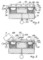
- Figure 1 is a diagrammatic section through a device for implementing the method, the device being designed to produce a flat panel of rectangular contour;
- Figure 2 is diagrammatic section through a device for producing a different object by the method of the invention;
- Figure 3 shows the device of Figure 1 in a different operating stage;
- Figure 4 is a perspective view of a toilet seat with its cover;
- Figure 5 is a section on the line V-V of Figure 4;
- Figure 6 is a diagrammatic partly full and partly sectional view of an apparatus for welding and trimming the edges to obtain a hollow structure.
- In Figure 1, which diagrammatically illustrates a device for producing a flat panel and by which the invention can be implemented, the
reference numeral 1 indicates a mould. In it there is a forming cavity 2, the shape of which corresponds to that of the flat rectangular panel to be obtained, this being in the form of a composite sandwich comprising two flat impactresistant polymethylmethacrylate sheets 3, 4 of thickness not exceeding 1.2 mm, with a layer of rigid compact or semiexpanded polyurethane 5 interposed. Themould 1 is provided internally withducts 6 connected to anexternal discharge 7 and connectable by means of anexternal valve 8 either to a source 9 of a hot water at a thermostatically controlled temperature or to asource 10 of water at mains temperature. - With the arrangement, the
mould 1 can be heated or cooled. - Other conventional means can be used for producing these heating and cooling effects.
- In the base wall of the mould-forming cavity 2 there are a plurality of holes, each of which represents the end of a
duct 11. All these ducts, which are provided within the mould interior, terminate in amanifold 12 connected to avacuum source 13 by avalve 14. - The mould is completed by a
cover 15, which is connected to therod 16 of a double-acting cylinder-piston unit 17 so that it can be moved towards and away from the mould, as indicated by the arrows A. The cover is also provided withvacuum ducts 18. These are connected to avacuum source 19 by way of avalve 20 and amanifold 21. - The
cover 15, which is also provided with water circulation for its thermostatically controlled heating in an analogous manner to themould 1, comprises on its lower face acontinuous side wall 22 defining a seat which is to hold the impactresistant polymethylmethacrylate sheet 3. - When the
cover 15 is moved up to the mould, this side wall mates with aperipherical recess 23 in the mould to form a seal. - With the
cover 15 withdrawn, the impact resistant polymethylmethacrylate sheet 4 is rested on thebase 23 of themould 1, and vacuum is applied through theducts 11. This vacuum must have an absolute value exceeding 350 mmHg. - The polyurethane mixture mixed with an inert charge of hollow glass microspheres is poured into the mould compartment 5. The reactive components of this mixture are polyols and isocyanates in a weight ratio of 1:0.95. The polyol contains the necessary catalysts, such as tertiary amines in a quantity of 1% by weight. The microsphere charge is equal to 30% by weight of the polyol.
- Expanding agents may be added. The impact
resistant polymethylmethacrylate sheet 3 is applied to the cover 15 (while this is separated from the mould 1), and is kept adhering by the vacuum applied through theduct 18. This vacuum is of the aforesaid value. - The
cover 15 is then applied to themould 1 by the cylinder-piston unit 17. - The mould (complete with cover) is heated to a temperature of between 40 and 70°C by feeding hot water through the
ducts 6 and through the ducts 101A1 of the cover. The water temperature is controlled thermostatically. Silicone oil or other non-stick material is previously applied to the side walls of the mould to prevent the polyurethane adhering to them. The vacuum is maintained continuously on thesheets 3 and 4 until the termination of the reaction, i.e. until the polyurethane is completely hardened. - When the reaction has terminated, the mould is cooled by a circulating cold water through the
ducts 6. After cooling, the vacuum is removed from theducts 11, but is retained in theducts 18. Thecover 15 is then raised and takes with it the panel obtained due to the presence of vacuum in theducts 18. The vacuum is removed, and the panel separates from thecover 15. - Figures 2 and 3 show a device for producing the toilet seat shown in Figures 4 and 5. The
reference numeral 1A indicates overall a mould. It comprises a formingcavity 2A, the shape of which cor responds to that of the object to be obtained, which in the illustrated example is theseat 3A of atoilet bowl 4A, as already stated. The cross-section through this seat is shown in Figure 5. - The
mould 1A is provided internally withducts 5A connected to anexternal discharge 6A and connectable by way of a valve 7A either to asource 8A of hot water at a thermostatically controlled temperature or to asource 9A of water at mains temperature. - In the wall which bounds the forming
cavity 2A there are a plurality of holes, each of which represents the end of aduct 10A. All these ducts, which are provided in the interior of the mould, terminate in a manifold 11 A connected to avacuum source 12A by way of avalve 13A. - An impact resistant polymethylmethacrylate (PMMA)
sheet 14A, for example having a thickness of 1 mm, is rested on the upper face of themould 1A. - This sheet is of a size such that its edge extends beyond the outer edge of the forming
cavity 2A. - A
removable heating device 15A consisting of abox member 16A holdingelectrical resistance elements 17A and areflector 18A is then superposed on thesheet 14A. These resistance elements are controlled by athermostat 19A disposed in themould 1A in contact with thesheet 14A. After this, hot water is fed through theducts 5A and theresistance elements 17A are fed with electricity. - The
sheet 14A thus becomes heated. When the set temperature of thethermostat 19A is reached, theresistance elements 17A are disconnected thevalve 13A is opened, and thesheet 14A, which has become plastic due to the heat, adheres against the walls of thecavity 2A by the action of the vacuum, to assume the configuration shown in Figure 3. - The
heating device 15A is removed, and a second impact resistant polymethylmethacrylate (PMMA)sheet 20A provided withholes 21A coinciding with the formingcavities 2A defined by the now shaped first sheet is placed on the mould. - A
metal presser plate 24A is applied to the top of thesheet 20A by a double-acting cylinder-piston unit 22A. Thepresser plate 24A, which is also heatable by circulating thermostatically controlled hot water, comprises channels, not visible, which can be connected to a vacuum source in a manner analogous to thecover 15 of Figure 1. - The plate comprises
holes 23A aligned with theholes 21 A of thesheet 20A. While maintaining vacuum on the twosheets polyurethane mixture 25A is fed into thecavity 2A through said aligned holes. - This feed can be effected either by a conventional polyurethane mixing heater, not shown, or, as shown in Figure 3, by using a container A in which the reactive components for forming the polyurethane together with an inert charge of hollow glass microspheres have been placed and mixed.
- The mould (together with the
presser plate 24A) is kept hot at a temperature of between 40 and 70°C by circulating hot water. The application of vacuum to thesheets - After cooling, vacuum is removed from the
ducts 10A but not from the ducts of theplate 24A, this latter is raised and the structure obtained is removed from the mould, after which vacuum is removed from theplate 24A and the structure is separated from this latter. - The structure comprises a peripheral flange and a central full zone (this zone is indicated by B in Figure 3). These parts, which are superfluous, are removed either by separating them manually or by placing the structure in a shearing machine comprising cutting tools shaped to follow the seat outline.
- Preferably, the method of the invention is implemented in the manner described hereinafter. Although the description given hereinafter relates by way of example to the production of a structure in the form of an ellipsoid of rotation, it will be apparent to an expert of the art that it can be applied analogously to the production of other objects, such as toilet lids, for which a detailed description is given hereinafter.
- Two half-
shells peripheral flange opening 103 for feeding the polyurethane mixture of the described type. The two half-shells are extracted from the mould, and one of them, as shown in Figure 6, is placed on anannular positioning member 104 with acutting edge 105 which follows the outline of the half-shell. - The other half-shell is then superposed on the preceding, and the periphery is then welded ultrasonically and trimmed (i.e. the
edges - In addition to the
ring 104, the welding and trimming apparatus comprises asonic applicator 109 having acavity 110 for holding the half-shell 101. The sonic applicator is connected to theoscillator 108. The sonic applicator and oscillator are connected to therod 106 of a double-acting cylinder-piston unit 107. - The
sonic applicator 109 is lowered onto the half-shell 101 and energised. When welding is complete, theexcess edges piston unit 107 and the presence of thecutter 105, to obtain a hollow ellipsoidal structure. This hollow structure is placed in a mould of corresponding shape formed from two mutually mobile parts, each of which comprises ducts for the cooling and heating fluid (analogous to theducts 6, 101A1 of Figures 1 and 3) and vacuum ducts (analogous to theducts opening 103. The vacuum (550 mmHg) is maintained during cooling, after which the mould is opened to release the structure obtained. - With this embodiment, the toilet seat is produced as follows: The
shell 14A (see Figure 3) is conventionally obtained by vacuum-forming starting from a polymethylmethacrylate sheet having a thickness for example of 1.2 mm. The shell is removed from the mould and placed on a positioner with cutting edges conceptually equivalent to that heretofore described, but of the correct shape for this purpose. A flat sheet such as that indicated by 20A in Figure 3 and comprising holes such as theholes 21 A is then superposed. Ultrasonic welding is then effected, followed by trimming of the excess material as described in relation to Figure 6. - The hollow structure is then inserted into a mould corresponding to that of Figure 3. A vacuum of 550 mmHg is applied, the temperature is controlled at 50°C and the polyurethane mixture is fed in. After cooling, the vacuum is released and the toilet seat removed.
- The use of other weldind systems such as hot blade, high frequency, laser and vibration systems instead of ultrasonics also falls within the scope of the invention.
- The following examples illustrate the products used for producing the structures according to the invention.
- To produce a pencil holder, two commercially available--impact resistant polymethylmethacrylate (PMMA) sheets were used, for example Oroglas DR, a trademark of Rohm and Haas, having a thickness of 0.7 mm and coloured yellow throughout. One of these sheets was hot vacuum-formed in a mould of the required shape in a manner analogous to that described heretofore, whereas the other sheet was used flat and provided with holes for receiving the component mixture for forming the polyurethane filling.
- In this mixture, the polyol/isocyanate ratio was 1:0.97.
- The carbonate filler ws 20% by weight of the polyol. The polyol was marketed under the name of AF 515 by POZZI-AROSIO di A. Pozzi & C. S.a.s. Industria Vernici Speciali.
- The isocyanate was marketed by the same company under the name "Indurente AF 515".
- In this example, the vacuum again remained applied to the sheets during the polyurethane reaction and until its hardening. The mould heating temperature was between 50 and 55°C.
- A shaped structure was required comprising a Q-shaped shell with a polyurethane interior.
- An impact resistant polymethylmethacrylate (PMMA) sheet of 0.6 mm thickness was hot vacuum-formed. A mixture composed of polyol and isocyanate in a weight ratio of 1:1 and with an inerts content equivalent to 25% by weight of the polyol was poured into the opening of the Q.
- A second sheet of impact resistant polymethylmethacrylate (PMMA) was therefore not used in this example.
- Again in this case, the operation took place under vacuum and at temperature as indicated heretofore.
- As already stated, the polymethylmethacrylate sheets can be vacuum-formed in a separate mould. The vacuum-formed sheet or sheets would then be transferred to a mould in which the polyurethane filling is inserted, while applying vacuum to the sheet or sheets.
Claims (12)
Priority Applications (1)
| Application Number | Priority Date | Filing Date | Title |
|---|---|---|---|
| AT87103935T ATE54604T1 (en) | 1986-04-01 | 1987-03-18 | PROCESS FOR MAKING COMPOSITES WITH A POLYURETHANE INTERIOR AND THE COMPOSITE SO MADE. |
Applications Claiming Priority (2)
| Application Number | Priority Date | Filing Date | Title |
|---|---|---|---|
| IT19945/86A IT1204295B (en) | 1986-04-01 | 1986-04-01 | PROCEDURE FOR OBTAINING COMPOSITE BODIES WITH POLYURETHANE INTERIOR AND COMPOSITE BODY OBTAINED |
| IT1994586 | 1986-04-01 |
Publications (3)
| Publication Number | Publication Date |
|---|---|
| EP0239877A2 EP0239877A2 (en) | 1987-10-07 |
| EP0239877A3 EP0239877A3 (en) | 1988-12-14 |
| EP0239877B1 true EP0239877B1 (en) | 1990-07-18 |
Family
ID=11162545
Family Applications (1)
| Application Number | Title | Priority Date | Filing Date |
|---|---|---|---|
| EP87103935A Expired - Lifetime EP0239877B1 (en) | 1986-04-01 | 1987-03-18 | Method for producing composite structures with a polyurethane interior, and the composite structure obtained |
Country Status (7)
| Country | Link |
|---|---|
| EP (1) | EP0239877B1 (en) |
| JP (1) | JPS635942A (en) |
| AT (1) | ATE54604T1 (en) |
| DE (1) | DE3763720D1 (en) |
| ES (1) | ES2016815B3 (en) |
| GR (1) | GR3000678T3 (en) |
| IT (1) | IT1204295B (en) |
Cited By (1)
| Publication number | Priority date | Publication date | Assignee | Title |
|---|---|---|---|---|
| CN101579957A (en) * | 2008-05-14 | 2009-11-18 | 拜耳材料科技贸易(上海)有限公司 | Composite material as well as preparation method and application thereof |
Families Citing this family (8)
| Publication number | Priority date | Publication date | Assignee | Title |
|---|---|---|---|---|
| US5075142A (en) * | 1990-02-20 | 1991-12-24 | E. I. Du Pont De Nemours And Company | Thermoformable composite sheet |
| DE4231396C1 (en) * | 1992-09-19 | 1994-04-21 | Roehm Gmbh | Process for the production of multilayer, trough-shaped or shell-shaped plastic bodies and such plastic bodies |
| DE19513171A1 (en) * | 1995-04-07 | 1996-10-31 | Roehm Gmbh | Polymer composite system |
| DE19519000A1 (en) * | 1995-05-24 | 1996-11-28 | Etol Vertriebs Gmbh | Containers and process for their manufacture |
| DE102006029613A1 (en) * | 2006-06-26 | 2007-12-27 | Röhm Gmbh | Transparent plastic composite |
| BR112015025932A2 (en) * | 2013-04-29 | 2017-07-25 | Basf Se | pmma elastomer layered composites that have enhanced properties |
| US10711442B2 (en) | 2016-04-26 | 2020-07-14 | Kohler Co. | Composite faucet body and internal waterway |
| US11118338B2 (en) | 2017-05-22 | 2021-09-14 | Kohler Co. | Plumbing fixtures with insert-molded components |
Family Cites Families (4)
| Publication number | Priority date | Publication date | Assignee | Title |
|---|---|---|---|---|
| US3379800A (en) * | 1964-08-20 | 1968-04-23 | Goodyear Tire & Rubber | Method for making cushion structure |
| US3871911A (en) * | 1973-06-01 | 1975-03-18 | Du Pont | Non-discoloring painted polyurethane |
| US4177099A (en) * | 1975-09-02 | 1979-12-04 | Ppg Industries, Inc. | Method of bonding polyurethane sheeting to acrylic or polyurethane sheeting in production of transparent windows |
| US4282285A (en) * | 1979-10-24 | 1981-08-04 | International Telephone & Telegraph Corporation | Process for preparing polyurethane molded part |
-
1986
- 1986-04-01 IT IT19945/86A patent/IT1204295B/en active
-
1987
- 1987-03-18 EP EP87103935A patent/EP0239877B1/en not_active Expired - Lifetime
- 1987-03-18 ES ES87103935T patent/ES2016815B3/en not_active Expired - Lifetime
- 1987-03-18 DE DE8787103935T patent/DE3763720D1/en not_active Expired - Fee Related
- 1987-03-18 AT AT87103935T patent/ATE54604T1/en not_active IP Right Cessation
- 1987-03-25 JP JP62071295A patent/JPS635942A/en active Pending
-
1990
- 1990-07-27 GR GR90400527T patent/GR3000678T3/en unknown
Cited By (1)
| Publication number | Priority date | Publication date | Assignee | Title |
|---|---|---|---|---|
| CN101579957A (en) * | 2008-05-14 | 2009-11-18 | 拜耳材料科技贸易(上海)有限公司 | Composite material as well as preparation method and application thereof |
Also Published As
| Publication number | Publication date |
|---|---|
| IT1204295B (en) | 1989-03-01 |
| EP0239877A2 (en) | 1987-10-07 |
| JPS635942A (en) | 1988-01-11 |
| DE3763720D1 (en) | 1990-08-23 |
| ES2016815B3 (en) | 1990-12-01 |
| ATE54604T1 (en) | 1990-08-15 |
| IT8619945A0 (en) | 1986-04-01 |
| EP0239877A3 (en) | 1988-12-14 |
| GR3000678T3 (en) | 1991-09-27 |
Similar Documents
| Publication | Publication Date | Title |
|---|---|---|
| EP0639440B1 (en) | Method of constructing a molded composite article comprising a foam backing | |
| US6685875B2 (en) | Foamed thermoplastic resin molding and process for producing the same | |
| EP0032052B1 (en) | Method for producing panels | |
| CA2134236C (en) | Method for shaping cover materials | |
| EP0239877A2 (en) | Method for producing composite structures with a polyurethane interior, and the composite structure obtained | |
| US5468433A (en) | Process for manufacturing a padded element using a cover preforming mandrel | |
| US3647588A (en) | Method for making foam panel | |
| US5456586A (en) | Apparatus for manufacturing articles made of polyurethane | |
| US4783302A (en) | Manufacturing method of surface materials having partially different materials | |
| US5811039A (en) | Process for fabricating bodies of polymeric material with foamed core | |
| KR910000316B1 (en) | Method for producing a polyurethane foam molding padding comprising a plurality of zones with different flexibility and padding produced by the method | |
| US5620636A (en) | Process for manufacturing foam molded product | |
| US7273571B2 (en) | Molded table and its method of manufacture | |
| US20040146704A1 (en) | Vehicular headliner and method for production thereof | |
| EP0242152A2 (en) | Method and apparatus for producing a seat cushion | |
| US3566447A (en) | Moulding equipment | |
| US20050129921A1 (en) | Molded article with foam-encased reinforcing member | |
| SE432381B (en) | SET TO MANUFACTURE A SUNSCREEN, WHICH IS ALSO EQUIPPED WITH A MIRROR | |
| JPS58171921A (en) | Manufacture of foam resin molded object shaped surface skin | |
| JPS6111778B2 (en) | ||
| EP0538475A1 (en) | Foamed synthetic resin molded product, method of molding said product, and metallic mold for internal foam molding | |
| JPS58171923A (en) | Method for manufacturing foamed olefin resin moldings | |
| JPS6150762B2 (en) | ||
| JPH06315993A (en) | Method of manufacturing foamed molded product | |
| JPH05285965A (en) | Method for producing foamed molded article having skin material |
Legal Events
| Date | Code | Title | Description |
|---|---|---|---|
| PUAI | Public reference made under article 153(3) epc to a published international application that has entered the european phase |
Free format text: ORIGINAL CODE: 0009012 |
|
| AK | Designated contracting states |
Kind code of ref document: A2 Designated state(s): AT BE CH DE ES FR GB GR LI LU NL SE |
|
| PUAL | Search report despatched |
Free format text: ORIGINAL CODE: 0009013 |
|
| AK | Designated contracting states |
Kind code of ref document: A3 Designated state(s): AT BE CH DE ES FR GB GR LI LU NL SE |
|
| 17P | Request for examination filed |
Effective date: 19890315 |
|
| 17Q | First examination report despatched |
Effective date: 19891011 |
|
| GRAA | (expected) grant |
Free format text: ORIGINAL CODE: 0009210 |
|
| AK | Designated contracting states |
Kind code of ref document: B1 Designated state(s): AT BE CH DE ES FR GB GR LI LU NL SE |
|
| REF | Corresponds to: |
Ref document number: 54604 Country of ref document: AT Date of ref document: 19900815 Kind code of ref document: T |
|
| REF | Corresponds to: |
Ref document number: 3763720 Country of ref document: DE Date of ref document: 19900823 |
|
| ET | Fr: translation filed | ||
| REG | Reference to a national code |
Ref country code: GR Ref legal event code: FG4A Free format text: 3000678 |
|
| PLBE | No opposition filed within time limit |
Free format text: ORIGINAL CODE: 0009261 |
|
| STAA | Information on the status of an ep patent application or granted ep patent |
Free format text: STATUS: NO OPPOSITION FILED WITHIN TIME LIMIT |
|
| 26N | No opposition filed | ||
| EPTA | Lu: last paid annual fee | ||
| EAL | Se: european patent in force in sweden |
Ref document number: 87103935.0 |
|
| REG | Reference to a national code |
Ref country code: GB Ref legal event code: IF02 |
|
| PGFP | Annual fee paid to national office [announced via postgrant information from national office to epo] |
Ref country code: GR Payment date: 20040227 Year of fee payment: 18 |
|
| PGFP | Annual fee paid to national office [announced via postgrant information from national office to epo] |
Ref country code: LU Payment date: 20040302 Year of fee payment: 18 |
|
| PGFP | Annual fee paid to national office [announced via postgrant information from national office to epo] |
Ref country code: GB Payment date: 20040303 Year of fee payment: 18 |
|
| PGFP | Annual fee paid to national office [announced via postgrant information from national office to epo] |
Ref country code: FR Payment date: 20040308 Year of fee payment: 18 |
|
| PGFP | Annual fee paid to national office [announced via postgrant information from national office to epo] |
Ref country code: NL Payment date: 20040315 Year of fee payment: 18 |
|
| PGFP | Annual fee paid to national office [announced via postgrant information from national office to epo] |
Ref country code: SE Payment date: 20040317 Year of fee payment: 18 |
|
| PGFP | Annual fee paid to national office [announced via postgrant information from national office to epo] |
Ref country code: AT Payment date: 20040318 Year of fee payment: 18 |
|
| PGFP | Annual fee paid to national office [announced via postgrant information from national office to epo] |
Ref country code: ES Payment date: 20040329 Year of fee payment: 18 |
|
| PGFP | Annual fee paid to national office [announced via postgrant information from national office to epo] |
Ref country code: BE Payment date: 20040401 Year of fee payment: 18 |
|
| PGFP | Annual fee paid to national office [announced via postgrant information from national office to epo] |
Ref country code: DE Payment date: 20040521 Year of fee payment: 18 |
|
| PGFP | Annual fee paid to national office [announced via postgrant information from national office to epo] |
Ref country code: CH Payment date: 20040623 Year of fee payment: 18 |
|
| PG25 | Lapsed in a contracting state [announced via postgrant information from national office to epo] |
Ref country code: LU Free format text: LAPSE BECAUSE OF NON-PAYMENT OF DUE FEES Effective date: 20050318 Ref country code: GB Free format text: LAPSE BECAUSE OF NON-PAYMENT OF DUE FEES Effective date: 20050318 Ref country code: AT Free format text: LAPSE BECAUSE OF NON-PAYMENT OF DUE FEES Effective date: 20050318 |
|
| PG25 | Lapsed in a contracting state [announced via postgrant information from national office to epo] |
Ref country code: SE Free format text: LAPSE BECAUSE OF NON-PAYMENT OF DUE FEES Effective date: 20050319 Ref country code: ES Free format text: LAPSE BECAUSE OF NON-PAYMENT OF DUE FEES Effective date: 20050319 |
|
| PG25 | Lapsed in a contracting state [announced via postgrant information from national office to epo] |
Ref country code: LI Free format text: LAPSE BECAUSE OF NON-PAYMENT OF DUE FEES Effective date: 20050331 Ref country code: CH Free format text: LAPSE BECAUSE OF NON-PAYMENT OF DUE FEES Effective date: 20050331 Ref country code: BE Free format text: LAPSE BECAUSE OF NON-PAYMENT OF DUE FEES Effective date: 20050331 |
|
| BERE | Be: lapsed |
Owner name: *ERREBI S.R.L. Effective date: 20050331 |
|
| PG25 | Lapsed in a contracting state [announced via postgrant information from national office to epo] |
Ref country code: NL Free format text: LAPSE BECAUSE OF NON-PAYMENT OF DUE FEES Effective date: 20051001 Ref country code: DE Free format text: LAPSE BECAUSE OF NON-PAYMENT OF DUE FEES Effective date: 20051001 |
|
| PG25 | Lapsed in a contracting state [announced via postgrant information from national office to epo] |
Ref country code: GR Free format text: LAPSE BECAUSE OF NON-PAYMENT OF DUE FEES Effective date: 20051004 |
|
| EUG | Se: european patent has lapsed | ||
| REG | Reference to a national code |
Ref country code: CH Ref legal event code: PL |
|
| GBPC | Gb: european patent ceased through non-payment of renewal fee |
Effective date: 20050318 |
|
| PG25 | Lapsed in a contracting state [announced via postgrant information from national office to epo] |
Ref country code: FR Free format text: LAPSE BECAUSE OF NON-PAYMENT OF DUE FEES Effective date: 20051130 |
|
| NLV4 | Nl: lapsed or anulled due to non-payment of the annual fee |
Effective date: 20051001 |
|
| REG | Reference to a national code |
Ref country code: FR Ref legal event code: ST Effective date: 20051130 |
|
| REG | Reference to a national code |
Ref country code: ES Ref legal event code: FD2A Effective date: 20050319 |
|
| BERE | Be: lapsed |
Owner name: *ERREBI S.R.L. Effective date: 20050331 |