EP0239287B1 - A method of forming a fixed structure - Google Patents
A method of forming a fixed structure Download PDFInfo
- Publication number
- EP0239287B1 EP0239287B1 EP87302116A EP87302116A EP0239287B1 EP 0239287 B1 EP0239287 B1 EP 0239287B1 EP 87302116 A EP87302116 A EP 87302116A EP 87302116 A EP87302116 A EP 87302116A EP 0239287 B1 EP0239287 B1 EP 0239287B1
- Authority
- EP
- European Patent Office
- Prior art keywords
- compartments
- tube
- rods
- transverse
- axes
- Prior art date
- Legal status (The legal status is an assumption and is not a legal conclusion. Google has not performed a legal analysis and makes no representation as to the accuracy of the status listed.)
- Expired - Lifetime
Links
- 238000000034 method Methods 0.000 title claims description 31
- 239000000463 material Substances 0.000 claims description 56
- 239000000945 filler Substances 0.000 claims description 25
- 229920002457 flexible plastic Polymers 0.000 claims description 17
- 239000002650 laminated plastic Substances 0.000 claims description 17
- 239000004568 cement Substances 0.000 claims description 9
- 239000000440 bentonite Substances 0.000 claims description 5
- 229910000278 bentonite Inorganic materials 0.000 claims description 5
- SVPXDRXYRYOSEX-UHFFFAOYSA-N bentoquatam Chemical compound O.O=[Si]=O.O=[Al]O[Al]=O SVPXDRXYRYOSEX-UHFFFAOYSA-N 0.000 claims description 5
- 239000013049 sediment Substances 0.000 claims description 5
- 239000004575 stone Substances 0.000 claims description 5
- -1 mine tailings Substances 0.000 claims description 4
- 239000000203 mixture Substances 0.000 claims description 4
- 239000004576 sand Substances 0.000 claims description 4
- 239000010881 fly ash Substances 0.000 claims description 3
- 239000002002 slurry Substances 0.000 claims description 3
- 229920003023 plastic Polymers 0.000 description 7
- 239000004033 plastic Substances 0.000 description 7
- 239000011435 rock Substances 0.000 description 6
- 229910052751 metal Inorganic materials 0.000 description 4
- 239000002184 metal Substances 0.000 description 4
- XLYOFNOQVPJJNP-UHFFFAOYSA-N water Substances O XLYOFNOQVPJJNP-UHFFFAOYSA-N 0.000 description 3
- PPBRXRYQALVLMV-UHFFFAOYSA-N Styrene Chemical compound C=CC1=CC=CC=C1 PPBRXRYQALVLMV-UHFFFAOYSA-N 0.000 description 2
- 230000015572 biosynthetic process Effects 0.000 description 2
- 238000005253 cladding Methods 0.000 description 2
- 238000005304 joining Methods 0.000 description 2
- 239000000696 magnetic material Substances 0.000 description 2
- 238000003466 welding Methods 0.000 description 2
- 239000004743 Polypropylene Substances 0.000 description 1
- 239000004411 aluminium Substances 0.000 description 1
- 229910052782 aluminium Inorganic materials 0.000 description 1
- XAGFODPZIPBFFR-UHFFFAOYSA-N aluminium Chemical compound [Al] XAGFODPZIPBFFR-UHFFFAOYSA-N 0.000 description 1
- 239000010425 asbestos Substances 0.000 description 1
- 238000010276 construction Methods 0.000 description 1
- 229910003460 diamond Inorganic materials 0.000 description 1
- 239000010432 diamond Substances 0.000 description 1
- 230000009977 dual effect Effects 0.000 description 1
- 239000011888 foil Substances 0.000 description 1
- 229920001903 high density polyethylene Polymers 0.000 description 1
- 239000004700 high-density polyethylene Substances 0.000 description 1
- 239000007788 liquid Substances 0.000 description 1
- 229920001684 low density polyethylene Polymers 0.000 description 1
- 239000004702 low-density polyethylene Substances 0.000 description 1
- 238000004519 manufacturing process Methods 0.000 description 1
- 239000004745 nonwoven fabric Substances 0.000 description 1
- 239000002985 plastic film Substances 0.000 description 1
- 229920006255 plastic film Polymers 0.000 description 1
- 229920000728 polyester Polymers 0.000 description 1
- 229920001155 polypropylene Polymers 0.000 description 1
- 229920000915 polyvinyl chloride Polymers 0.000 description 1
- 239000004800 polyvinyl chloride Substances 0.000 description 1
- 229910052895 riebeckite Inorganic materials 0.000 description 1
- 239000010802 sludge Substances 0.000 description 1
- 239000002023 wood Substances 0.000 description 1
- 239000002759 woven fabric Substances 0.000 description 1
Images
Classifications
-
- E—FIXED CONSTRUCTIONS
- E02—HYDRAULIC ENGINEERING; FOUNDATIONS; SOIL SHIFTING
- E02B—HYDRAULIC ENGINEERING
- E02B3/00—Engineering works in connection with control or use of streams, rivers, coasts, or other marine sites; Sealings or joints for engineering works in general
- E02B3/04—Structures or apparatus for, or methods of, protecting banks, coasts, or harbours
- E02B3/06—Moles; Piers; Quays; Quay walls; Groynes; Breakwaters ; Wave dissipating walls; Quay equipment
-
- E—FIXED CONSTRUCTIONS
- E02—HYDRAULIC ENGINEERING; FOUNDATIONS; SOIL SHIFTING
- E02D—FOUNDATIONS; EXCAVATIONS; EMBANKMENTS; UNDERGROUND OR UNDERWATER STRUCTURES
- E02D29/00—Independent underground or underwater structures; Retaining walls
- E02D29/02—Retaining or protecting walls
- E02D29/0258—Retaining or protecting walls characterised by constructional features
- E02D29/0283—Retaining or protecting walls characterised by constructional features of mixed type
Definitions
- This invention relates to a method of forming a fixed structure adapted to bear a laterally acting load, on a support, which may be used for example as a retaining wall for a river bank or as a dam wall.
- a support which may be used for example as a retaining wall for a river bank or as a dam wall.
- Such a method is known from WO-A-8101722, for example.
- a method of forming a fixed structure adapted to bear a laterally acting load on a support from an elongate tube of a flexible plastic or plastic laminate material divided by dividing walls of a flexible plastic or plastic laminate material into a plurality of compartments running the length of the tube so that the elongate tube divided by dividing walls has a honeycomb structure, comprising the steps of:
- a method of forming a fixed structure adapted to bear a laterally acting load on a support from an elongate tube of a flexible plastic or plastic laminate material divided by dividing walls of a flexible plastic or plastic laminate material into a plurality of compartments running the length of the tube so that the elongate tube divided by dividing walls has a honeycomb structure comprising the steps of:
- the fixed structure constructed by the methods described above to bear a laterally acting load may be for example, a retaining wall adapted to retain earthworks such as river banks, or a retaining wall adapted to retain water, i.e. a dam wall.
- each compartment of the elongate tube comprises a cell in a honeycomb structure.
- Each cell may have a round, square, diamond, hexagonal or octagonal shape or any other suitable shape.
- the flexible material may be either a flexible plastic material or a flexible plastic laminate material.
- the plastic material may be a conventional plastic material, a biaxially oriented plastic material, or a woven or non-woven fabric. Suitable plastics include high and low density polyethylene, polypropylene, styrene-based plastics, polyesters and polyvinyl chloride.
- the plastic laminate material may be any suitable laminate wherein one layer at least is a plastic material.
- the plastic laminate material comprises a thin metal foil or sheet such as aluminium sandwiched between two sheets of a plastic material as described above.
- the elongate tube having the honeycomb structure may be made, for example, by the method described in United States Patent No. 4,478,659.
- This patent discloses, inter alia, a method of joining a first sheet of two sheets of a non-magnetic material which are joined to each other along a join line to the third sheet of a non-magnetic material along a join line.
- This method comprises the steps of locating the three sheets close to a magnet with a third sheet adjacent the first sheet, locating a body which is attracted by the magnet between the first sheet and the second sheet so that the first sheet and the third sheet are brought together in a zone between the magnet and the body with the second sheet below the body, causing the first sheet and the third sheet to be moved through the zone, and joining the third sheet to the first sheet in the zone or immediately after the third sheet and the first sheet have passed through the zone to form the join line.
- the first sheet and the second sheet are joined to each other along two substantially parallel join lines and the third sheet is joined to the first sheet along a join line which is intermediate the join lines of the first and second sheets. The result of this is a honeycomb structure.
- each compartment of the elongate tube comprises a cell in the honeycomb structure formed between two adjacent sheets of a suitable material.
- each cell of the honeycomb structure may vary according to the use to which the fixed structure is to be put. Generally, each cell will have a diameter of 100 mm to 1 meter or larger.
- the flexible material comprises a flexible plastic material
- it may comprise a plastic film having a thickness of 50 ⁇ m to 500 ⁇ m.
- the length of the elongate tube may be any desired length, for example, 1 meter to 1000 meters.
- the flexible material may be micro-perforated to permit the egress of liquid from the tube but not the egress of the particulate filler material.
- the tube is located in position on the support with one end of the tube above the other end and with the compartments running in a direction transverse to the direction of the load.
- the tube will be located in a substantially vertical position, i.e. with the axes of the compartments being substantially vertical.
- the tube may either be substantially vertical or may be positioned at an angle to the vertical which is less than 90°.
- the load will generally act horizontally on the fixed structure.
- step (b) of the first method of the invention rods or ties or the like are passed through the elongate tube either all in a direction transverse to the axes of the compartments or all in a direction parallel to the axes of the compartments or some in a direction transverse to the axes of the compartments and the remainder in a direction parallel to the axes of the compartments.
- the rods may be located in a direction which is transverse to the axes of the compartments and which is either not transverse to or transverse to the direction of the load, and thus two sets of rods may be used, which sets are both transverse to the axes of the compartments, with one set being not transverse to the direction of the load and the other set being transverse to the direction of the load so that the sets intersect with each other to form a grid-type structure.
- the rods may be located parallel to the axes of the compartments, i.e. the rods are located in some or all of the compartments.
- the rods may be transverse to the axes of the compartments and not transverse to the direction of the load, or transverse to the axes of the compartments and transverse to the direction of the load, or parallel to the axes of the compartments, or any combination of the above.
- the rods are fixed in position.
- the rods may be attached to a support structure located outside the tube, either on one or both sides of the tube.
- the support structure may be a scaffolding structure or the like.
- the outer compartments of the tube may be filled with a material which sets such as cement or concrete, thus holding the rods in position.
- the rods may be attached to stays, which in turn are anchored to the ground.
- the rods When the rods are transverse to the axes of the compartments and transverse to the direction of the load, the rods may be attached to a support structure located outside the tube or to a fixture located in the vicinity of the tube.
- the rods may be attached to the rock faces or the like forming the sides of the dam wall.
- each rod When the rods are parallel to the axes of the compartments, each rod may be attached at one end to an anchor means attached to the support, with the other end of the rod protruding from the top of the compartment. Thereafter, after the compartments have been filled with a filler material, a rigid member such as a cast concrete slab may be placed on top of the tube.
- the free ends of the rods may either be embedded in the rigid member during its formation or thereafter, or may pass through the rigid member so that they protrude on top of the rigid member. This may be desirable where it is desired to tension the rods to impart a compressive load to the structure.
- step (d) of the first method of the invention some or all of the compartments of the tube are filled with a suitable filler material.
- the filler material may be any suitable material such as sand, cement, crushed stone, a particulate-containing sludge or slurry, mine tailings, fly ash, river bed sediment, or bentonite or a mixture of two or more thereof.
- the preferred filler material is a mixture of sand or fine milled stone with bentonite, preferably 4 - 10 % by weight of bentonite.
- the fixed structure constructed by the method of the invention gains its great strength under a laterally acting load because of the fact that most or all of the compartments are adjacent two or more other compartments which are also filled with the filler material.
- each compartment supports and is supported by its adjacent compartments. This prevents the compartments from rupturing as they are simultaneously supported by their neighbours and provide support to their neighbours.
- Figure 1 is a schematic side view of a dam wall constructed according to a method of the invention
- Figure 2 is a plan view of the dam wall of Figure 1;
- Figure 3 is a schematic perspective view of a retaining wall constructed according to a method of the invention.
- Figure 4 is a schematic side view of another dam wall constructed according to a method of the invention.
- a dam wall 10 is formed between two rock faces 12 and 14.
- the dam wall 10 is adapted to bear a laterally acting load illustrated by the arrow A.
- the dam wall 10 is constructed from an elongate tube 16 of a flexible plastic or plastic laminate material divided by dividing walls of a flexible plastic or plastic laminate material into a plurality of compartments 18 running the length of the tube 16.
- the compartments 18 form the cells of the honeycomb structure.
- Rods 20 are passed through the compartments 18 in a direction which is substantially parallel to the direction of the laterally acting load indicated by the arrow A.
- the rods 20 are attached to a scaffolding structure 22 located on either side of the tube 16.
- the compartments 18 of the tube 16 are filled with a suitable filler material such as river bed sediment.
- the dam wall 10 is constructed as follows. Firstly, the elongate tube 16 is located in position between the rock faces 12 and 14. The elongate tube 16 may be attached to the rock faces 12 and 14, if desired, to support it. Thereafter, the rods 20 are passed through the elongate tube 16. The elongate tube 16 may include pre-punched holes through which the rods 20 can be passed. As an alternative, the rods 20 may have sharpened ends or heated ends and may pierce the elongate tube as they are pushed therethrough. The rods 20 are then attached to the scaffolding structure 22 located on either side of the tube 16 so that the tube 16 is supported in position. Finally, some or all of the compartments 18 of the tube 16 are filled with a suitable filler material.
- the dam wall 10 has great strength under a laterally acting load because of the fact that most or all of the compartments are adjacent two or more other compartments which are also filled with a particulate filler material. This prevents the compartments from rupturing as they are simultaneously supported by their neighbours and provide support to their neighbours.
- a retaining wall 30 for a river bank 32 comprises an elongate tube 34 of a flexible plastic or plastic laminate material divided by dividing walls of a flexible plastic or plastic laminate material into a plurality of compartments or cells 36 running the length of the tube 34.
- Rods 38 pass through the tube 34 in a direction transverse to the axis of the compartments 36.
- the rods 38 are fixed in position by means of cement which is located in the compartments 36A.
- the other ends of the rods 38 are located in the earth of the river bank 32.
- the rest of the compartments 36B of the elongate tube 34 are filled with a suitable filler material.
- the retaining wall 30 is constructed as follows.
- the elongate tube 34 is located in position at an angle of less than 90° to the vertical.
- the rods 38 are passed through the compartments 36 of the elongate tube 34 in a direction which is not parallel to the direction of the laterally acting load B but which is at an angle thereto and which direction is transverse to the axes of the compartments 36.
- the rods 38 are then fixed in position by pouring cement into the outer compartments 36A of the elongate tube 34. Thereafter, the remainder of the compartments 36B of the elongate tube 34 are filled with a suitable filler material.
- a cladding sheet made of metal, wood, asbestos filled cement, concrete or the like may be located on the outside of the elongate tube 34 and the rods 38 may be attached to the metal cladding sheet to hold them in position.
- the retaining wall 30 is capable of bearing a laterally acting load because of the fact that most or all of the compartments are adjacent two or more other compartments which are also filled with filler material.
- a dam wall 40 is formed between two rock faces 42 and 44 and on a support or base 46.
- the dam wall 40 is adapted to bear a laterally acting load like the dam wall 10 of Figure 1.
- the dam wall 40 is constructed from elongate tubes 48 of a flexible plastic or plastic laminate material divided by dividing walls of a flexible plastic or plastic laminate material into a plurality of compartments 50 running the lengths of the tubes 48. Again, the compartments 50 form the cells of the honeycomb structure. Embedded into the base 46 are a series of anchor bolts 52. Attached to each of the anchor bolts 52 is a tie or rod 54 which runs through the lengths of the compartments 50, parallel to the axes of the compartments 50.
- the compartments 50 of the tubes 48 are filled with a suitable filler material such as river bed sediment.
- a suitable filler material such as river bed sediment.
- the free ends of the rods 54 are embedded in a concrete slab 56 on top of the top tube 48.
- the dam wall 40 includes further rods 58 which are located transverse to the axes of the compartments 50 and also transverse to the direction of the laterally acting load.
- the rods 58 are embedded in the rock faces 44 and 42.
- the dam wall 40 has great strength under a laterally acting load because of the fact that the whole structure is tied between the base 46 of the dam wall 40 and a rigid slab 56 on top of the dam wall 40. This prevents the dam wall 40 from being pushed over by the laterally acting load, i.e. the weight of the water.
- the rods may only run the length of the compartments 50 of the lowest tube 48.
- the free ends of the rods 54 are then embedded in a concrete slab on top of the lowest tube 48.
- the second lowest tube 48 is then located on the slab. It may be tied to the slab or not as is required.
- some of the compartments 50 may be filled with a settable material such as cement so that a rigid join is formed between a rod 54 and a rod 58.
- the rods 54 and the rods 58 may also be connected to each other in other suitable ways.
- the rods serve the dual function of the fixed structure once it is constructed and of supporting the elongate tube in position before it is filled with the filler material.
- rigid support elements such as metal or wooden props may be located in some compartments prior to being filled with the filler material, to support the tube during construction of the fixed structure.
- the fixed structure of the invention may form simply the cave of a dam wall.
- the fixed structure may be covered on one or both sides by stones, brides or the like.
- the fixed structure constructed according to the method of the invention has several advantages. Firstly, it is easy and cheap to manufacture. Secondly, the fixed structure is able to bear high laterally acting loads. Thirdly, when the fixed structure comprises a dam wall, it is more robust than a conventional earth dam wall. The dam wall resulting from the method of the invention will not readily breach when water folws over the top thereof, and will not readily "pipe", i.e. permit the formation of a hole therethrough, unlike conventional dam walls.
Landscapes
- Engineering & Computer Science (AREA)
- General Engineering & Computer Science (AREA)
- Environmental & Geological Engineering (AREA)
- Civil Engineering (AREA)
- Structural Engineering (AREA)
- Ocean & Marine Engineering (AREA)
- Mechanical Engineering (AREA)
- Life Sciences & Earth Sciences (AREA)
- General Life Sciences & Earth Sciences (AREA)
- Mining & Mineral Resources (AREA)
- Paleontology (AREA)
- Revetment (AREA)
Description
- This invention relates to a method of forming a fixed structure adapted to bear a laterally acting load, on a support, which may be used for example as a retaining wall for a river bank or as a dam wall. Such a method is known from WO-A-8101722, for example.
- According to the invention there is provided a method of forming a fixed structure adapted to bear a laterally acting load on a support, from an elongate tube of a flexible plastic or plastic laminate material divided by dividing walls of a flexible plastic or plastic laminate material into a plurality of compartments running the length of the tube so that the elongate tube divided by dividing walls has a honeycomb structure, comprising the steps of:
- (a) locating the tube in position on the support with one end of the tube above the other end of the tube and with the compartments running in a direction transverse to the direction of the load;
- (b) passing rods or the like through the elongate tube either all in direction transverse to the axes of the compartments or all in a direction parallel to the axes of the compartments or some in a direction transverse to the axes of the compartments and the remainder in a direction parallel to the axes of the compartments, the rods or the like being spaced from one another;
- (c) fixing the rods in position; and
- (d) filling some or all of the compartments with a suitable filler material so that at least some of the compartments are adjacent two or more other compartments filled with the filler material to support and be supported by the adjacent compartments.
- According to another aspect of the invention, there is provided a method of forming a fixed structure adapted to bear a laterally acting load on a support from an elongate tube of a flexible plastic or plastic laminate material divided by dividing walls of a flexible plastic or plastic laminate material into a plurality of compartments running the length of the tube so that the elongate tube divided by dividing walls has a honeycomb structure, comprising the steps of:
- (a) fixing a plurality of anchor means into the support;
- (b) locating the tube in position on the support with one end of the tube above the other end of the tube and with the compartments running in a direction transverse to the direction of the load;
- (c) locating rods or the like in some or all of the compartments with one end of each rod or the like being attached to an anchor means and with the other end of each rod or the like protruding from the top of the compartments;
- (d) passing rods or the like through the elongate tube in a direction transverse to the axes of the compartments, the rods or the like being spaced from one another and fixing the rods or the like in position;
- (e) filling some or all of the compartments with a suitable filler material so that at least some of the compartments are adjacent two or more other compartments filled with the filler material to support and be supported by the adjacent compartments; and
- (f) placing a rigid member on top of the tube with the free ends of the rods or the like which are located in the compartments fixed into or passing through the rigid member.
- According to a further aspect of the invention, there is provided a fixed structure made by one or other of the methods described above.
- The fixed structure constructed by the methods described above to bear a laterally acting load may be for example, a retaining wall adapted to retain earthworks such as river banks, or a retaining wall adapted to retain water, i.e. a dam wall.
- The elongate tube divided by dividing walls into compartments has a honeycomb structure. In other words, each compartment of the elongate tube comprises a cell in a honeycomb structure. Each cell may have a round, square, diamond, hexagonal or octagonal shape or any other suitable shape.
- The flexible material may be either a flexible plastic material or a flexible plastic laminate material. The plastic material may be a conventional plastic material, a biaxially oriented plastic material, or a woven or non-woven fabric. Suitable plastics include high and low density polyethylene, polypropylene, styrene-based plastics, polyesters and polyvinyl chloride. The plastic laminate material may be any suitable laminate wherein one layer at least is a plastic material. Preferably the plastic laminate material comprises a thin metal foil or sheet such as aluminium sandwiched between two sheets of a plastic material as described above.
- The elongate tube having the honeycomb structure may be made, for example, by the method described in United States Patent No. 4,478,659. This patent discloses, inter alia, a method of joining a first sheet of two sheets of a non-magnetic material which are joined to each other along a join line to the third sheet of a non-magnetic material along a join line. This method comprises the steps of locating the three sheets close to a magnet with a third sheet adjacent the first sheet, locating a body which is attracted by the magnet between the first sheet and the second sheet so that the first sheet and the third sheet are brought together in a zone between the magnet and the body with the second sheet below the body, causing the first sheet and the third sheet to be moved through the zone, and joining the third sheet to the first sheet in the zone or immediately after the third sheet and the first sheet have passed through the zone to form the join line. Generally the first sheet and the second sheet are joined to each other along two substantially parallel join lines and the third sheet is joined to the first sheet along a join line which is intermediate the join lines of the first and second sheets. The result of this is a honeycomb structure. The sheets may be joined to each other by heat welding or by ultrasonic welding which creates a continuous welded join line along the length of the sheets. Thus, each compartment of the elongate tube comprises a cell in the honeycomb structure formed between two adjacent sheets of a suitable material.
- The cross-section or area of each cell of the honeycomb structure may vary according to the use to which the fixed structure is to be put. Generally, each cell will have a diameter of 100 mm to 1 meter or larger.
- Where the flexible material comprises a flexible plastic material, it may comprise a plastic film having a thickness of 50 µm to 500 µm. The length of the elongate tube may be any desired length, for example, 1 meter to 1000 meters.
- The flexible material may be micro-perforated to permit the egress of liquid from the tube but not the egress of the particulate filler material.
- In step (a) of the first method of the invention, the tube is located in position on the support with one end of the tube above the other end and with the compartments running in a direction transverse to the direction of the load. For example, where the fixed structure is a dam wall, the tube will be located in a substantially vertical position, i.e. with the axes of the compartments being substantially vertical. Where the fixed structure is a retaining wall for earthworks or the like, the tube may either be substantially vertical or may be positioned at an angle to the vertical which is less than 90°. The load will generally act horizontally on the fixed structure.
- In step (b) of the first method of the invention, rods or ties or the like are passed through the elongate tube either all in a direction transverse to the axes of the compartments or all in a direction parallel to the axes of the compartments or some in a direction transverse to the axes of the compartments and the remainder in a direction parallel to the axes of the compartments. Thus, the rods may be located in a direction which is transverse to the axes of the compartments and which is either not transverse to or transverse to the direction of the load, and thus two sets of rods may be used, which sets are both transverse to the axes of the compartments, with one set being not transverse to the direction of the load and the other set being transverse to the direction of the load so that the sets intersect with each other to form a grid-type structure. Alternatively, or in addition, the rods may be located parallel to the axes of the compartments, i.e. the rods are located in some or all of the compartments. Thus, to summarise, the rods may be transverse to the axes of the compartments and not transverse to the direction of the load, or transverse to the axes of the compartments and transverse to the direction of the load, or parallel to the axes of the compartments, or any combination of the above.
- In step (c) of the first method of the invention, the rods are fixed in position. When the rods are transverse to the axes of the compartments, and not transverse to the direction of the load, the rods may be attached to a support structure located outside the tube, either on one or both sides of the tube. For example, the support structure may be a scaffolding structure or the like. As an alternative, the outer compartments of the tube may be filled with a material which sets such as cement or concrete, thus holding the rods in position. As a further alternative, the rods may be attached to stays, which in turn are anchored to the ground. When the rods are transverse to the axes of the compartments and transverse to the direction of the load, the rods may be attached to a support structure located outside the tube or to a fixture located in the vicinity of the tube. For example, when the fixed structure comprises a dam wall, the rods may be attached to the rock faces or the like forming the sides of the dam wall.
- When the rods are parallel to the axes of the compartments, each rod may be attached at one end to an anchor means attached to the support, with the other end of the rod protruding from the top of the compartment. Thereafter, after the compartments have been filled with a filler material, a rigid member such as a cast concrete slab may be placed on top of the tube. The free ends of the rods may either be embedded in the rigid member during its formation or thereafter, or may pass through the rigid member so that they protrude on top of the rigid member. This may be desirable where it is desired to tension the rods to impart a compressive load to the structure.
- In step (d) of the first method of the invention, some or all of the compartments of the tube are filled with a suitable filler material. The filler material may be any suitable material such as sand, cement, crushed stone, a particulate-containing sludge or slurry, mine tailings, fly ash, river bed sediment, or bentonite or a mixture of two or more thereof. The preferred filler material is a mixture of sand or fine milled stone with bentonite, preferably 4 - 10 % by weight of bentonite. The fixed structure constructed by the method of the invention gains its great strength under a laterally acting load because of the fact that most or all of the compartments are adjacent two or more other compartments which are also filled with the filler material. Thus, each compartment supports and is supported by its adjacent compartments. This prevents the compartments from rupturing as they are simultaneously supported by their neighbours and provide support to their neighbours.
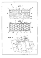
- Figure 1 is a schematic side view of a dam wall constructed according to a method of the invention;
- Figure 2 is a plan view of the dam wall of Figure 1;
- Figure 3 is a schematic perspective view of a retaining wall constructed according to a method of the invention; and
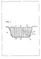
- Figure 4 is a schematic side view of another dam wall constructed according to a method of the invention.
- Referring to Figures 1 and 2, a
dam wall 10 is formed between tworock faces 12 and 14. Thedam wall 10 is adapted to bear a laterally acting load illustrated by the arrow A. - The
dam wall 10 is constructed from an elongate tube 16 of a flexible plastic or plastic laminate material divided by dividing walls of a flexible plastic or plastic laminate material into a plurality of compartments 18 running the length of the tube 16. The compartments 18 form the cells of the honeycomb structure.Rods 20 are passed through the compartments 18 in a direction which is substantially parallel to the direction of the laterally acting load indicated by the arrow A. Therods 20 are attached to ascaffolding structure 22 located on either side of the tube 16. The compartments 18 of the tube 16 are filled with a suitable filler material such as river bed sediment. - The
dam wall 10 is constructed as follows. Firstly, the elongate tube 16 is located in position between the rock faces 12 and 14. The elongate tube 16 may be attached to the rock faces 12 and 14, if desired, to support it. Thereafter, therods 20 are passed through the elongate tube 16. The elongate tube 16 may include pre-punched holes through which therods 20 can be passed. As an alternative, therods 20 may have sharpened ends or heated ends and may pierce the elongate tube as they are pushed therethrough. Therods 20 are then attached to thescaffolding structure 22 located on either side of the tube 16 so that the tube 16 is supported in position. Finally, some or all of the compartments 18 of the tube 16 are filled with a suitable filler material. - The
dam wall 10 has great strength under a laterally acting load because of the fact that most or all of the compartments are adjacent two or more other compartments which are also filled with a particulate filler material. This prevents the compartments from rupturing as they are simultaneously supported by their neighbours and provide support to their neighbours. - Referring to Figure 3, a retaining
wall 30 for ariver bank 32 comprises an elongate tube 34 of a flexible plastic or plastic laminate material divided by dividing walls of a flexible plastic or plastic laminate material into a plurality of compartments orcells 36 running the length of the tube 34.Rods 38 pass through the tube 34 in a direction transverse to the axis of thecompartments 36. Therods 38 are fixed in position by means of cement which is located in thecompartments 36A. The other ends of therods 38 are located in the earth of theriver bank 32. The rest of thecompartments 36B of the elongate tube 34 are filled with a suitable filler material. - The retaining
wall 30 is constructed as follows. The elongate tube 34 is located in position at an angle of less than 90° to the vertical. Therods 38 are passed through thecompartments 36 of the elongate tube 34 in a direction which is not parallel to the direction of the laterally acting load B but which is at an angle thereto and which direction is transverse to the axes of thecompartments 36. Therods 38 are then fixed in position by pouring cement into theouter compartments 36A of the elongate tube 34. Thereafter, the remainder of thecompartments 36B of the elongate tube 34 are filled with a suitable filler material. - As an alternative to the
compartments 36A being filled with a cement or the like, a cladding sheet made of metal, wood, asbestos filled cement, concrete or the like may be located on the outside of the elongate tube 34 and therods 38 may be attached to the metal cladding sheet to hold them in position. - Again, the retaining
wall 30 is capable of bearing a laterally acting load because of the fact that most or all of the compartments are adjacent two or more other compartments which are also filled with filler material. - Referring to Figure 4, a
dam wall 40 is formed between tworock faces base 46. Thedam wall 40 is adapted to bear a laterally acting load like thedam wall 10 of Figure 1. - The
dam wall 40 is constructed from elongate tubes 48 of a flexible plastic or plastic laminate material divided by dividing walls of a flexible plastic or plastic laminate material into a plurality ofcompartments 50 running the lengths of the tubes 48. Again, thecompartments 50 form the cells of the honeycomb structure. Embedded into the base 46 are a series ofanchor bolts 52. Attached to each of theanchor bolts 52 is a tie orrod 54 which runs through the lengths of thecompartments 50, parallel to the axes of thecompartments 50. - The
compartments 50 of the tubes 48 are filled with a suitable filler material such as river bed sediment. The free ends of therods 54 are embedded in aconcrete slab 56 on top of the top tube 48. - The
dam wall 40 includesfurther rods 58 which are located transverse to the axes of thecompartments 50 and also transverse to the direction of the laterally acting load. Therods 58 are embedded in the rock faces 44 and 42. - The
dam wall 40 has great strength under a laterally acting load because of the fact that the whole structure is tied between the base 46 of thedam wall 40 and arigid slab 56 on top of thedam wall 40. This prevents thedam wall 40 from being pushed over by the laterally acting load, i.e. the weight of the water. - As an alternative, the rods may only run the length of the
compartments 50 of the lowest tube 48. The free ends of therods 54 are then embedded in a concrete slab on top of the lowest tube 48. The second lowest tube 48 is then located on the slab. It may be tied to the slab or not as is required. - As a further alternative, some of the
compartments 50 may be filled with a settable material such as cement so that a rigid join is formed between arod 54 and arod 58. Therods 54 and therods 58 may also be connected to each other in other suitable ways. - The rods serve the dual function of the fixed structure once it is constructed and of supporting the elongate tube in position before it is filled with the filler material.
- In addition, rigid support elements such as metal or wooden props may be located in some compartments prior to being filled with the filler material, to support the tube during construction of the fixed structure.
- Further, the fixed structure of the invention may form simply the cave of a dam wall. In other words, the fixed structure may be covered on one or both sides by stones, brides or the like.
- The fixed structure constructed according to the method of the invention has several advantages. Firstly, it is easy and cheap to manufacture. Secondly, the fixed structure is able to bear high laterally acting loads. Thirdly, when the fixed structure comprises a dam wall, it is more robust than a conventional earth dam wall. The dam wall resulting from the method of the invention will not readily breach when water folws over the top thereof, and will not readily "pipe", i.e. permit the formation of a hole therethrough, unlike conventional dam walls.
Claims (11)
- A method of forming a fixed structure (10, 30, 40) adapted to bear a laterally acting load on a support (46) from an elongate tube (16, 34, 48) of a flexible plastic or plastic laminate material divided by dividing walls of a flexible plastic or plastic laminate material into a plurality of compartments (18, 36, 50) running the length of the tube (16, 34, 48) so that the elongate tube (16, 34, 48) divided by dividing walls has a honeycomb structure, comprises the steps of:(a) locating the tube (16, 34, 48) in position on the support (48) with one end of the tube (16, 34, 48) above the other end of the tube (16, 34, 48) and with the compartments (18, 36, 50) running in a direction transverse to the direction of the load;(b) passing rods (20, 38, 54, 58) or the like through the elongate tube (16, 34, 48) in a direction transverse to the axes of the compartments (18, 36, 50) and/or in a direction parallel to the axes of the compartments (18, 36, 50), the rods (20, 38, 54, 58) or the like being spaced from one another;(c) fixing the rods (20, 38, 54, 58) in position; and(d) filling some or all of the compartments (18, 36, 50) with a suitable filler material so that at least some of the compartments (18, 36, 50) are adjacent two or more other compartments (18, 36, 50) filled with the filler material to support and be supported by the adjacent compartments (18, 36, 50).
- A method according to Claim 1, wherein in step (b) the rods (20, 38) are passed through the tube (16, 34) in a direction transverse to the axes of the compartments (18, 36) and not transverse to the direction of the laterally acting load.
- A method according to Claim 1 wherein in step (b), the rods (58) are passed through the tube (48) in a direction transverse to the axes of the compartments (50) and transverse to the direction of the laterally acting load.
- A method according to Claim 1 wherein in step (b) some of the rods (20, 38, 58) are passed through the tube (16, 34, 48) in a direction transverse to the axes of the compartments (18, 36, 50) and not transverse to the direction of the laterally acting load and the remainder of the rods are passed in a direction transverse to the axes of the compartments and transverse to the direction of the laterally acting load.
- A method according to any one of Claims 1 to 4 wherein in step (b) the rods (54) are located in a direction parallel to the axes of the compartments (48).
- A method according to any of Claims 1 to 5 wherein the filler material comprises sand, cement, crushed stone, a particulate-containing slurry, mine tailings, fly ash, river bed sediment or bentonite or a mixture of two or more thereof.
- A method of forming a fixed structure (40) adapted to bear a laterally acting load on a support (46) from an elongate tube (48) of a flexible plastic or plastic laminate material divided by dividing walls of a flexible plastic or plastic laminate material into a plurality of compartments (50) running the length of the tube (48) so that the elongate tube (48) divided by dividing walls has a honeycomb structure, comprises the steps of:(a) fixing a plurality of anchor means (52) into the support (46);(b) locating the tube (48) in position on the support (46) with one end of the tube (48) above the other end of the tube (48) and with the compartments (50) running in a direction transverse to the direction of the load;(c) locating rods (54) or the like in some or all of the compartments (50) with one end of each rod (54) or the like being attached to an anchor means (52) and with the other end of each rod (54) or the like protruding from the top of the compartments (50);(d) passing rods (58) or the like through the elongate tube (48) in a direction transverse to the axes of the compartments (50), the rods (58) or the like being spaced from one another and fixing the rods (58) or the like in position;(e) filling some or all of the compartments (50) with a suitable filler material so that at least some of the compartments (50) are adjacent two or more other compartments (50) filled with the filler material to support and be supported by the adjacent compartments (50; and(f) placing a rigid member (56) on top of the tube (48) with the free ends of the rods (54) or the like which are located in the compartments (50) fixed into or passing through the rigid member (56).
- A method according to claim 7 wherein in step (d) the rods are passed through the tube in a direction transverse to the axes of the compartments and not transverse to the direction of the laterally acting load.
- A method according to claim 7 wherein in step (d), the rods (58) are passed through the tube (48) in a direction transverse to the axes of the compartments (50) and transverse to the direction of the laterally acting load.
- A method according to claim 7 wherein in step (d), the rods are passed through the tube in a direction transverse to the axes of the compartments and not transverse to the direction of the laterally acting load and in a direction transverse to the axes of the compartments and transverse to the direction of the laterally acting load.
- A method according to any one of claims 7 to 10 wherein the filler material comprises sand, cement, crushed stone, a particulate-containing slurry, mine tailings, fly ash river bed sediment or bentonite or a mixture of two or more thereof.
Priority Applications (1)
| Application Number | Priority Date | Filing Date | Title |
|---|---|---|---|
| AT87302116T ATE61432T1 (en) | 1986-03-26 | 1987-03-11 | PROCEDURE FOR MAKING A CONSTRUCTION. |
Applications Claiming Priority (4)
| Application Number | Priority Date | Filing Date | Title |
|---|---|---|---|
| ZA862260 | 1986-03-26 | ||
| ZA862260 | 1986-03-26 | ||
| ZA868158 | 1986-10-27 | ||
| ZA868158 | 1986-10-27 |
Publications (2)
| Publication Number | Publication Date |
|---|---|
| EP0239287A1 EP0239287A1 (en) | 1987-09-30 |
| EP0239287B1 true EP0239287B1 (en) | 1991-03-06 |
Family
ID=27136962
Family Applications (1)
| Application Number | Title | Priority Date | Filing Date |
|---|---|---|---|
| EP87302116A Expired - Lifetime EP0239287B1 (en) | 1986-03-26 | 1987-03-11 | A method of forming a fixed structure |
Country Status (3)
| Country | Link |
|---|---|
| EP (1) | EP0239287B1 (en) |
| AU (1) | AU597717B2 (en) |
| DE (1) | DE3768298D1 (en) |
Families Citing this family (8)
| Publication number | Priority date | Publication date | Assignee | Title |
|---|---|---|---|---|
| FR2639379B1 (en) * | 1988-11-21 | 1991-11-22 | Lefoll Pierre | PROCESS FOR THE CONSTRUCTION OF A PERRE OF PROTECTION OF A STRUCTURE SUCH AS A BANK, A JET OR THE LIKE, AND PERRE SO OBTAINED |
| FR2699948B1 (en) * | 1992-12-24 | 1995-02-10 | Armater | Method for making a support structure (wall or similar structure) and new type of structure thus produced. |
| CA2111063C (en) * | 1993-02-18 | 1996-04-23 | Gary M. Bach | Reinforced cell material |
| FR2729874B1 (en) * | 1995-01-31 | 1997-03-14 | France Dechets | PROCESS FOR THE STORAGE OF ULTIMATE WASTE IN A STORAGE CENTER |
| PT1105580E (en) | 1998-08-07 | 2003-10-31 | Alethea Rosalind Melanie Hall | METHOD OF FORMATION OF AN ARTIFICIAL RECIFE UNIT |
| ATE473325T1 (en) * | 2008-04-16 | 2010-07-15 | Matthaei Bauunternehmen Gmbh & | WORKING DEVICE FOR WORKING, IN PARTICULAR SEALING, FLOOR SURFACES UNDER WATER, IN PARTICULAR SOLES AND SANKS OF WATERWAYS, IN PARTICULAR CANALS, METHOD FOR CONSTRUCTING THE SAME, METHOD FOR MOVING THE SAME, METHOD FOR SEALING FLOOR SURFACES USING DERSELBEN, E.O. |
| CN101892664B (en) * | 2010-07-21 | 2011-11-09 | 东南大学 | Bored concrete pile group construction method of plastic honeycomb pipe retaining wall and honeycombed bored concrete pile |
| CN113026660B (en) * | 2021-03-24 | 2022-10-28 | 上海瀛盛市政工程有限公司 | Wood pile ecological revetment and construction method thereof |
Family Cites Families (6)
| Publication number | Priority date | Publication date | Assignee | Title |
|---|---|---|---|---|
| US3247673A (en) * | 1961-06-06 | 1966-04-26 | Nat Gypsum Co | Laminated retaining wall and method of constructing same |
| AU545244B2 (en) * | 1979-12-06 | 1985-07-04 | Garry Randall Hart | Method of and apparatus for building construction |
| WO1981001722A1 (en) * | 1979-12-06 | 1981-06-25 | G Hart | Method of and apparatus for building construction |
| US4478659A (en) * | 1981-11-24 | 1984-10-23 | Hall Alethea R M | Method of joining sheets of a non-magnetic material together |
| EP0138259A3 (en) * | 1983-09-29 | 1986-04-16 | Fluvio Labor, Personenvennootschap met beperkte aansprakelijkheid | Drainage structure and method of making a reinforced dike slope |
| FR2557172B1 (en) * | 1983-12-23 | 1987-04-24 | Aubert J | PREFABRICATED CIVIL ENGINEERING STRUCTURE, APPLICATION TO THE CONSTRUCTION OF A STRUCTURE AND STRUCTURE THEREOF |
-
1987
- 1987-03-11 DE DE8787302116T patent/DE3768298D1/en not_active Expired - Fee Related
- 1987-03-11 EP EP87302116A patent/EP0239287B1/en not_active Expired - Lifetime
- 1987-09-10 AU AU78243/87A patent/AU597717B2/en not_active Ceased
Also Published As
| Publication number | Publication date |
|---|---|
| AU597717B2 (en) | 1990-06-07 |
| EP0239287A1 (en) | 1987-09-30 |
| DE3768298D1 (en) | 1991-04-11 |
| AU7824387A (en) | 1989-03-16 |
Similar Documents
| Publication | Publication Date | Title |
|---|---|---|
| DE112016002341B4 (en) | Arrangement of several tubular piles arranged next to one another with a heat transfer pipe arrangement embedded in at least one prefabricated tubular pile and a pump unit | |
| US6395372B1 (en) | Cell confinement structure | |
| CA1335757C (en) | Unit comprising mesh combined with geotextile | |
| EP0239287B1 (en) | A method of forming a fixed structure | |
| CN108343077A (en) | A kind of Miniature anti-slide pile composite structure and its construction method | |
| CN111648492A (en) | A construction method of a built-in assembled H-shaped steel skeleton Tibetan stone masonry wall | |
| US6558085B1 (en) | Mine support and method of forming the same | |
| CA1247384A (en) | Support member | |
| JPH04108916A (en) | Construction method for reinforced banking body | |
| US4591297A (en) | Method of building strengthened, embanked foundation | |
| GB2131063A (en) | Method of and apparatus for retaining earth formations | |
| US4519730A (en) | Method for constructing underground structure | |
| JP2001032231A (en) | Lattice type installation material, wave absorbing structure using it, hume pipe used for the structure, and construction method of wave absorbing structure | |
| JP2024068713A (en) | Construction method for support structure | |
| WO2004055273A1 (en) | Multi-level undercut excavation method using superimposed posts | |
| JPH02176008A (en) | Construction of revetment | |
| JPS59150810A (en) | Coastal structure with caisson and its construction | |
| DE102005013993B3 (en) | Foundation for a flood protection | |
| CN207987917U (en) | A kind of frost-cracking-preventing steel-pipe pile suitable for frost zone bridge subaqueous work | |
| CN216515650U (en) | Combined flexible protective net | |
| CN108643385A (en) | The construction method of steel wire net rack sandwich concrete bearing wall, building and the building | |
| CN205421908U (en) | A single face formwork for basement is built | |
| CN208777492U (en) | Steel wire net rack sandwich concrete bearing wall building | |
| JP2576902B2 (en) | Construction methods and buildings in landfills | |
| GB2156871A (en) | Soil anchor; anchored earth structures |
Legal Events
| Date | Code | Title | Description |
|---|---|---|---|
| PUAI | Public reference made under article 153(3) epc to a published international application that has entered the european phase |
Free format text: ORIGINAL CODE: 0009012 |
|
| AK | Designated contracting states |
Kind code of ref document: A1 Designated state(s): AT BE CH DE ES FR GB GR IT LI LU NL SE |
|
| 17P | Request for examination filed |
Effective date: 19880324 |
|
| 17Q | First examination report despatched |
Effective date: 19890929 |
|
| GRAA | (expected) grant |
Free format text: ORIGINAL CODE: 0009210 |
|
| AK | Designated contracting states |
Kind code of ref document: B1 Designated state(s): AT BE CH DE ES FR GB GR IT LI LU NL SE |
|
| PG25 | Lapsed in a contracting state [announced via postgrant information from national office to epo] |
Ref country code: IT Free format text: LAPSE BECAUSE OF FAILURE TO SUBMIT A TRANSLATION OF THE DESCRIPTION OR TO PAY THE FEE WITHIN THE PRE;WARNING: LAPSES OF ITALIAN PATENTS WITH EFFECTIVE DATE BEFORE 2007 MAY HAVE OCCURRED AT ANY TIME BEFORE 2007. THE CORRECT EFFECTIVE DATE MAY BE DIFFERENT FROM THE ONE RECORDED.SCRIBED TIME-LIMIT Effective date: 19910306 Ref country code: NL Effective date: 19910306 Ref country code: BE Effective date: 19910306 Ref country code: AT Effective date: 19910306 Ref country code: SE Effective date: 19910306 Ref country code: GR Free format text: LAPSE BECAUSE OF FAILURE TO SUBMIT A TRANSLATION OF THE DESCRIPTION OR TO PAY THE FEE WITHIN THE PRESCRIBED TIME-LIMIT Effective date: 19910306 Ref country code: LI Effective date: 19910306 Ref country code: CH Effective date: 19910306 |
|
| REF | Corresponds to: |
Ref document number: 61432 Country of ref document: AT Date of ref document: 19910315 Kind code of ref document: T |
|
| PG25 | Lapsed in a contracting state [announced via postgrant information from national office to epo] |
Ref country code: LU Free format text: LAPSE BECAUSE OF NON-PAYMENT OF DUE FEES Effective date: 19910331 |
|
| REF | Corresponds to: |
Ref document number: 3768298 Country of ref document: DE Date of ref document: 19910411 |
|
| ET | Fr: translation filed | ||
| REG | Reference to a national code |
Ref country code: CH Ref legal event code: PL |
|
| PG25 | Lapsed in a contracting state [announced via postgrant information from national office to epo] |
Ref country code: ES Free format text: LAPSE BECAUSE OF FAILURE TO SUBMIT A TRANSLATION OF THE DESCRIPTION OR TO PAY THE FEE WITHIN THE PRESCRIBED TIME-LIMIT Effective date: 19910617 |
|
| NLV1 | Nl: lapsed or annulled due to failure to fulfill the requirements of art. 29p and 29m of the patents act | ||
| PLBE | No opposition filed within time limit |
Free format text: ORIGINAL CODE: 0009261 |
|
| STAA | Information on the status of an ep patent application or granted ep patent |
Free format text: STATUS: NO OPPOSITION FILED WITHIN TIME LIMIT |
|
| 26N | No opposition filed | ||
| PGFP | Annual fee paid to national office [announced via postgrant information from national office to epo] |
Ref country code: DE Payment date: 19940506 Year of fee payment: 8 |
|
| PGFP | Annual fee paid to national office [announced via postgrant information from national office to epo] |
Ref country code: FR Payment date: 19940519 Year of fee payment: 8 |
|
| PGFP | Annual fee paid to national office [announced via postgrant information from national office to epo] |
Ref country code: GB Payment date: 19940610 Year of fee payment: 8 |
|
| PG25 | Lapsed in a contracting state [announced via postgrant information from national office to epo] |
Ref country code: GB Effective date: 19950311 |
|
| GBPC | Gb: european patent ceased through non-payment of renewal fee |
Effective date: 19950311 |
|
| PG25 | Lapsed in a contracting state [announced via postgrant information from national office to epo] |
Ref country code: FR Free format text: LAPSE BECAUSE OF NON-PAYMENT OF DUE FEES Effective date: 19951130 |
|
| PG25 | Lapsed in a contracting state [announced via postgrant information from national office to epo] |
Ref country code: DE Effective date: 19951201 |
|
| REG | Reference to a national code |
Ref country code: FR Ref legal event code: ST |