EP0239014A2 - Methods and circuit arrangements for controlling the operating point of final video stages - Google Patents
Methods and circuit arrangements for controlling the operating point of final video stages Download PDFInfo
- Publication number
- EP0239014A2 EP0239014A2 EP87104064A EP87104064A EP0239014A2 EP 0239014 A2 EP0239014 A2 EP 0239014A2 EP 87104064 A EP87104064 A EP 87104064A EP 87104064 A EP87104064 A EP 87104064A EP 0239014 A2 EP0239014 A2 EP 0239014A2
- Authority
- EP
- European Patent Office
- Prior art keywords
- screen
- deflection
- vertical
- circuit
- circuit arrangement
- Prior art date
- Legal status (The legal status is an assumption and is not a legal conclusion. Google has not performed a legal analysis and makes no representation as to the accuracy of the status listed.)
- Withdrawn
Links
- 238000000034 method Methods 0.000 title claims abstract description 17
- 230000001105 regulatory effect Effects 0.000 abstract description 4
- 238000010586 diagram Methods 0.000 description 10
- 239000003990 capacitor Substances 0.000 description 7
- 238000011161 development Methods 0.000 description 4
- 230000018109 developmental process Effects 0.000 description 4
- 238000005259 measurement Methods 0.000 description 3
- 230000003321 amplification Effects 0.000 description 2
- 230000008859 change Effects 0.000 description 2
- 230000008878 coupling Effects 0.000 description 2
- 238000010168 coupling process Methods 0.000 description 2
- 238000005859 coupling reaction Methods 0.000 description 2
- 230000001939 inductive effect Effects 0.000 description 2
- 238000003199 nucleic acid amplification method Methods 0.000 description 2
- 230000008901 benefit Effects 0.000 description 1
- 230000015572 biosynthetic process Effects 0.000 description 1
- 230000000903 blocking effect Effects 0.000 description 1
- 230000001276 controlling effect Effects 0.000 description 1
- 238000010894 electron beam technology Methods 0.000 description 1
- 238000012986 modification Methods 0.000 description 1
- 230000004048 modification Effects 0.000 description 1
- 239000004065 semiconductor Substances 0.000 description 1
- 238000007493 shaping process Methods 0.000 description 1
Images

Classifications
-
- H—ELECTRICITY
- H04—ELECTRIC COMMUNICATION TECHNIQUE
- H04N—PICTORIAL COMMUNICATION, e.g. TELEVISION
- H04N9/00—Details of colour television systems
- H04N9/64—Circuits for processing colour signals
- H04N9/645—Beam current control means
-
- G—PHYSICS
- G09—EDUCATION; CRYPTOGRAPHY; DISPLAY; ADVERTISING; SEALS
- G09G—ARRANGEMENTS OR CIRCUITS FOR CONTROL OF INDICATING DEVICES USING STATIC MEANS TO PRESENT VARIABLE INFORMATION
- G09G1/00—Control arrangements or circuits, of interest only in connection with cathode-ray tube indicators; General aspects or details, e.g. selection emphasis on particular characters, dashed line or dotted line generation; Preprocessing of data
- G09G1/04—Deflection circuits ; Constructional details not otherwise provided for
-
- G—PHYSICS
- G09—EDUCATION; CRYPTOGRAPHY; DISPLAY; ADVERTISING; SEALS
- G09F—DISPLAYING; ADVERTISING; SIGNS; LABELS OR NAME-PLATES; SEALS
- G09F13/00—Illuminated signs; Luminous advertising
- G09F13/20—Illuminated signs; Luminous advertising with luminescent surfaces or parts
- G09F13/22—Illuminated signs; Luminous advertising with luminescent surfaces or parts electroluminescent
- G09F2013/222—Illuminated signs; Luminous advertising with luminescent surfaces or parts electroluminescent with LEDs
-
- G—PHYSICS
- G09—EDUCATION; CRYPTOGRAPHY; DISPLAY; ADVERTISING; SEALS
- G09F—DISPLAYING; ADVERTISING; SIGNS; LABELS OR NAME-PLATES; SEALS
- G09F13/00—Illuminated signs; Luminous advertising
- G09F13/20—Illuminated signs; Luminous advertising with luminescent surfaces or parts
- G09F13/22—Illuminated signs; Luminous advertising with luminescent surfaces or parts electroluminescent
- G09F2013/227—Electroluminescent displays for vehicles
Definitions
- the invention relates to a circuit arrangement according to the type of the main claim.
- circuit arrangements for regulating the operating point of the video output stage are known, in which a voltage corresponding to the beam current is compared with a reference voltage during a line within the vertical frequency blanking interval after the vertical return and the result of the comparison is stored during the subsequent field.
- the operating point of the video output stage is set as a function of the stored voltage.
- the grid is usually written larger than the screen or the area of the screen released by a frame. It is therefore possible to start the vertical traverse to sense the beam current to a size suitable for deriving a measured value without this being visible on the screen.
- Color monitors intended as data display devices have therefore not previously been equipped with the control of the working point of the video output stages known from television receivers.
- the method according to the invention with the characterizing features of the main claim has the advantage that an operating point control is possible without the measurement lines being disruptive.
- a further development of the invention provides that the selected lines are written on a part of the screen covered by a frame.
- This development can be used advantageously in the usual color monitors, which are provided with a frame in front of the screen.
- the color value signals R, G, B are sent to the video amplifiers 4, 5, 6 supplied, the outputs of which are each connected to a cathode 7, 8, 9 of a color picture tube 10.
- the amplifiers 4, 5, 6 are constructed in the same way, only the amplifier 6 is shown in more detail.
- the color value signal arrives at a video preamplifier which, among other things, enables a contrast adjustment with the aid of an adjustable gain.
- the output of the video preamplifier 11 is connected via a capacitor 12 to the base of a transistor 13 connected as an emitter follower.
- the base of the transistor 13 is periodically connected to a constant potential during the line frequency return, as a result of which the video signals receive a constant DC voltage value in a manner known per se.
- the clamping circuit 14 is connected in the same way to the video amplifiers 4 and 5.
- the emitter of transistor 13 is connected to ground potential via load resistor 15, while the collector of transistor 13 is connected to a positive pole 16 of an operating voltage source.
- the color value signal is fed via a coupling resistor 17 to the input of an inverting amplifier 18, the no-load gain of which is so high that the effective amplification corresponds approximately to the ratio between the negative feedback resistor 19 and the coupling resistor 17.
- the video signals already have an amplitude sufficient to control the picture tube. They are conducted to the cathode 9 of the color picture tube 10 via an output transistor 20 connected as an emitter follower.
- a voltage can be removed which is proportional to the beam current. This is evaluated in a manner known per se in a control circuit for controlling the operating point of the video amplifier 18, 20.
- the voltage taken from the resistor 21 is fed to an input 23 of a differential amplifier 24, at the other input 25 of which there is a reference voltage.
- the differential amplifier 24 is a switchable operational amplifier, the output 26 of which only emits a signal when a corresponding signal is present at a switching input EN. During the remaining time, the output 26 is switched to high resistance. A pulse corresponding to an active line within the vertical frequency blanking interval after the beam return is now fed to the switching input EN. During this time, the result of the difference formation between the voltage corresponding to the beam current and a reference voltage is output by the differential amplifier 24 and a capacitor 27 is charged to this value. The switchable differential amplifier 24 and the capacitor 27 thus form a sample and hold circuit.
- the voltage present at the capacitor 27 is fed to the base of a transistor 28, which is connected together with the resistor 29 as an impedance converter.
- the base of transistor 28 forms a high-resistance input, so that the charge of capacitor 27 is practical during a field period table remains constant.
- the control circuit is provided in triplicate, in each case for one of the color value signals R, G, B.
- the control voltage reaches the input of the inverting amplifier 18 via an adjustable resistor 31.
- the gain of the by the video processor can be increased and the control circuit formed by the video amplifier can be set without changing the amplification for the video signal supplied by the transistor 13.
- Diagram a) represents the output voltage of a vertical deflection circuit.
- the vertical return occurs between t1 and t2. Due to the inductive component of the deflection coil and the faster current change during the return, a voltage pulse is generated between t1 and t2 in a manner known per se.
- the output voltage of the vertical deflection circuit is essentially time-linear.
- the color picture tube 10 (FIG. 1) is supplied with a vertical frequency blanking pulse, as shown in diagram b), which lasts until time t3.
- the cathode ray is released for one or more lines following the beam blanking with the aid of the pulse shown in diagram c). If it is released for several lines, the cathode ray between these lines is blanked out horizontally.
- the grid is usually written so large in television sets that it goes beyond the frame which covers the edge of the picture tube.
- the upper edge of the grid is therefore not visible in television sets, so that the lines that are blanked for the beam current control do not appear to be a nuisance either.
- the grid is written smaller so that it is completely visible.
- the electron beam is additionally deflected during these lines according to the present invention.
- a pulse according to diagram d) is generated in a pulse shaping circuit known per se and therefore not shown in detail.
- the pulse begins at t2, ie before the start of the measuring lines at t3. Furthermore, the safety edge of the pulse at t5 is slightly later than the end of the measuring lines at t4 for safety reasons.
- Diagram e) shows the course of the vertical deflection current in the usual raster representation. From the voltage pulse shown in diagram d), the current pulse shown in diagram f) is obtained, which is superimposed on the usual vertical deflection current, so that the one in diagram g) shown vertical deflection current arises.
- the beam jumps up by a predetermined value, so that the lines which are scanned for beam current control are written at a point on the screen which is covered by a frame .
- the beam can be deflected into an area that does not belong to the active screen, which is therefore not provided with phosphors.
- a series circuit comprising a vertical deflection coil 42, a capacitor 43 and a negative feedback resistor 44 is connected to the output of a vertical deflection circuit 41.
- a voltage can be removed from the negative feedback resistor 44, which voltage can be fed to a control input of the vertical deflection circuit 41. Since the voltage at the negative feedback resistor 44 corresponds to the current flowing through the vertical deflection coil 42, the vertical deflection current can be regulated in a manner known per se be that there is as linear a vertical deflection on the screen as possible.
- a vertical-frequency pulse is taken from the vertical deflection circuit 41 and fed to a pulse shaper 45, at the output of which the drive pulse shown in FIG. 2d) is present.
- This pulse is fed to an amplifier 46, the output of which is connected via a resistor 47 to the negative feedback path of the vertical deflection circuit.
- the amplifier 47 connects the resistor 47 in parallel with the negative feedback resistor 44.
- the resulting resistance value is thus smaller, as a result of which the voltage supplied to the vertical deflection circuit also becomes smaller with the same deflection current.
- a smaller deflection current is simulated, so to speak, to the vertical deflection circuit, as a result of which the deflection current is correspondingly increased during the actuation pulse.
- FIG. 4 shows another circuit for carrying out the method according to the invention, in which the vertical deflection circuit 41, the vertical deflection coil 42, the capacitor 43 and the negative feedback resistor 44 are arranged in the same way as in the circuit arrangement according to FIG. 3.
- a pulse shaper 45 is also used to shape the control pulse for an amplifier 48, which, however, does not engage in the negative feedback circuit as in the circuit arrangement according to FIG. 3, but rather supplies additional current directly to the deflection coil 42 via a resistor 49.
Abstract
Bei einem Verfahren zur Regelung des Arbeitspunktes von Videoendstufen von Monitoren, bei denen der für die Darstellung von Information vorgesehene Teil des Rasters vollständig auf dem sichtbaren Teil des Bildschirms geschrieben wird, wird der Strahlstrom während ausgewählter, für die Darstellung der Information auf dem Bildschirm nicht benötigter Zeilen gemessen und zur Regelung des Arbeitspunktes benutzt. Durch Beeinflussung des Vertikal-Ablenkstroms werden die ausgewählten Zeilen auf einem nicht sichtbaren Teil des Bildschirms geschrieben. In a method for regulating the operating point of video output stages of monitors, in which the part of the grid intended for the display of information is written entirely on the visible part of the screen, the beam current is selected during the process of not being required for the display of the information on the screen Lines measured and used to regulate the operating point. By influencing the vertical deflection current, the selected lines are written on an invisible part of the screen.
Description
Die Erfindung geht aus von einer Schaltungsanordnung nach der Gattung des Hauptanspruchs.The invention relates to a circuit arrangement according to the type of the main claim.
Für Farbfernsehgeräte sind Schaltungsanordnungen zur Regelung des Arbeitspunktes der Videoendstufe bekannt, bei welchen eine dem Strahlstrom entsprechende Spannung während einer Zeile innerhalb des vertikalfrequenten Austastintervalls nach dem Vertikalrücklauf mit einer Vergleichsspannung verglichen wird und das Ergebnis des Vergleichs während des darauffolgenden Halbbildes gespeichert wird. In Abhängigkeit von der gespeicherten Spannung erfolgt eine Einstellung des Arbeitspunktes der Videoendstufe.For color television sets, circuit arrangements for regulating the operating point of the video output stage are known, in which a voltage corresponding to the beam current is compared with a reference voltage during a line within the vertical frequency blanking interval after the vertical return and the result of the comparison is stored during the subsequent field. The operating point of the video output stage is set as a function of the stored voltage.
Bei Fernsehgeräten wird überlicherweise das Raster größer als der Bildschirm bzw. die von einem Rahmen freigegebene Fläche des Bildschirms geschrieben. Es ist daher möglich, zu Beginn des Vertikalhinlaufs den Strahlstrom auf eine zur Ableitung eines Meßwertes geeignete Größe aufzutasten, ohne daß dieses auf dem Bildschirm sichtbar wird.In television sets, the grid is usually written larger than the screen or the area of the screen released by a frame. It is therefore possible to start the vertical traverse to sense the beam current to a size suitable for deriving a measured value without this being visible on the screen.
Bei Datensichtgeräten wird jedoch das gesamte Raster auf dem Bildschirm dargestellt, so daß eine Auftastung des Strahlstroms, um Meßzeilen zu gewinnen, an den Rändern des Rasters nicht durchgeführt werden kann, ohne daß diese Zeilen sichtbar werden.In data display devices, however, the entire grid is displayed on the screen, so that the beam current cannot be gated at the edges of the grid in order to obtain measurement lines without these lines becoming visible.
Es wurden daher als Datensichtgeräte vorgesehene Farbmonitore bisher nicht mit der von Fernsehempfängern bekannten Regelung des Arbeitspunktes der Videoendstufen ausgerüstet.Color monitors intended as data display devices have therefore not previously been equipped with the control of the working point of the video output stages known from television receivers.
Das erfindungsgemäße Verfahren mit den kennzeichnenden Merkmalen des Hauptanspruchs hat den Vorteil, daß eine Arbeitspunktregelung möglich ist, ohne daß die Meßzeilen störend in Erscheinung treten.The method according to the invention with the characterizing features of the main claim has the advantage that an operating point control is possible without the measurement lines being disruptive.
Eine Weiterbildung der Erfindung sieht vor, daß die ausgewählten Zeilen auf einem von einem Rahmen abgedeckten Teil des Bildschirmes geschrieben werden. Diese Weiterbildung kann in vorteilhafter Weise bei den üblichen Farbmonitoren angewendet werden, welche mit einem Rahmen vor dem Bildschirm versehen sind.A further development of the invention provides that the selected lines are written on a part of the screen covered by a frame. This development can be used advantageously in the usual color monitors, which are provided with a frame in front of the screen.
Eine andere Weiterbildung, daß nämlich die ausgewählten Zeilen außerhalb des aktiven Bildschirms geschrieben werden, ermöglicht eine Anwendung des erfindungsgemäßen Verfahrens bei Geräten ohne Rahmen.Another development, namely that the selected lines are written outside the active screen, enables the method according to the invention to be used in devices without a frame.
Durch die in den Unteransprüchen aufgeführten Maßnahmen sind vorteilhafte Weiterbildungen und Verbesserungen der im Hauptanspruch angegebenen Erfindung möglich.Advantageous further developments and improvements of the invention specified in the main claim are possible through the measures listed in the subclaims.
Insbesondere sind in den Unteransprüchen vorteilhafte Schaltungen zur Durchführung des erfindungsgemäßen Verfahrens angegeben.In particular, advantageous circuits for carrying out the method according to the invention are specified in the subclaims.
Ausführungsbeispiele der Erfindung sind in der Zeichnung an Hand mehrerer Figuren dargestellt und in der nachfolgenden Beschreibung näher erläutert. Es zeigt:
- Fig. 1 eine Schaltungsanordnung zur Regelung des Arbeitspunktes von Videoendstufen,
- Fig. 2 Diagramme von bei der Schaltung nach Fig. 1 und bei dem erfindungsgemäßen Verfahren auftretenden Spannungen und Strömen,
- Fig. 3 ein erstes Ausführungsbeispiel für eine Schaltungsanordnung zur Durchführung des erfindungsgemäßen Verfahrens und
- Fig. 4 ein zweites Ausführungsbeispiel.
- 1 shows a circuit arrangement for regulating the operating point of video output stages,
- 2 shows diagrams of voltages and currents occurring in the circuit according to FIG. 1 and in the method according to the invention,
- Fig. 3 shows a first embodiment of a circuit arrangement for performing the method according to the invention and
- Fig. 4 shows a second embodiment.
Gleiche Teile sind in den Figuren mit gleichen Bezugszeichen versehen.Identical parts are provided with the same reference symbols in the figures.
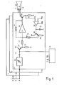
Fig 1 dient zur Erläuterung des Prinzips der an sich bekannten Strahlstrom- bzw. Arbeitspunktregelung, auch Sperrpunktregelung genannt. Über die Eingänge 1, 2, 3 der Schaltungsanordnung nach Fig. 1 werden die Farbwertsignale R, G, B den Videoverstärkern 4, 5, 6 zugeführt, deren Ausgänge mit je einer Kathode 7, 8, 9 einer Farbbildröhre 10 verbunden sind.1 serves to explain the principle of the beam current or working point control known per se, also called the blocking point control. Via the
Da die Verstärker 4, 5, 6 gleichartig aufgebaut sind, ist lediglich der Verstärker 6 genauer dargestellt. Vom Eingang 3 gelangt das Farbwertsignal zu einem Videovorverstärker, welcher unter anderem mit Hilfe einer einstellbaren Verstärkung eine Kontrasteinstellung ermöglicht. Der Ausgang des Videovorverstärkers 11 ist über einen Kondensator 12 mit der Basis eines als Emitterfolger geschalteten Transistors 13 verbunden. In einer Klemmschaltung 14 wird periodisch während des zeilenfrequenten Rücklaufs die Basis des Transistors 13 mit konstantem Potential verbunden, wodurch die Videosignale in an sich bekannter Weise einen konstanten Gleichspannungswert erhalten. Die Klemmschaltung 14 ist in gleicher Weise mit den Videoverstärkern 4 und 5 verbunden.Since the
Der Emitter des Transistors 13 ist über den Arbeitswiderstand 15 mit Massepotential verbunden, während der Kollektor des Transistors 13 an einen positiven Pol 16 einer Betriebsspannungsquelle angeschlossen ist. Über einen Koppelwiderstand 17 wird das Farbwertsignal zum Eingang eines invertierenden Verstärkers 18 geführt, dessen Leerlaufverstärkung derart hoch ist, daß die effektive Verstärkung etwa dem Verhältnis zwischen dem Gegenkopplungswiderstand 19 und dem Koppelwiderstand 17 entspricht. Am Ausgang des Verstärkers 18 haben die Videosignale bereits eine zur Ansteuerung der Bildröhre ausreichende Amplitude. Sie werden uber einen als Emitterfolger geschalteten Ausgangstransistor 20 zur Kathode 9 der Farbbildröhre 10 geleitet.The emitter of
An einem zwischen den Kollektor des Ausgangstransistors 20 und Massepotential geschalteten Widerstand 21 ist eine Spannung abnehmbar, welche proportional zum Strahlstrom ist. Diese wird in an sich bekannter Weise in einer Regelschaltung zur Regelung des Arbeitspunktes des Videoverstärkers 18, 20 ausgewertet.At a
Dazu wird die vom Widerstand 21 abgenommene Spannung einem Eingang 23 eines Differenzverstärkers 24 zugefuhrt, an dessen anderem Eingang 25 eine Bezugsspannung liegt.For this purpose, the voltage taken from the
Der Differenzverstärker 24 ist ein schaltbarer Operationsverstärker, dessen Ausgang 26 nur ein Signal abgibt, wenn an einem Schalteingang EN ein entsprechendes Signal ansteht. Während der übrigen Zeit ist der Ausgang 26 hochohmig geschaltet. Dem Schalteingang EN wird nun ein Impuls zugeführt, der einer aktiven Zeile innerhalb des vertikalfrequenten Austastintervalls nach dem Strahlrücklauf entspricht. Während dieser Zeit wird also das Ergebnis der Differenzbildung zwischen der dem Strahlstrom entsprechenden Spannung und einer Bezugsspannung vom Differenzverstärker 24 abgegeben und ein Kondensator 27 auf diesen Wert aufgeladen. Der schaltbare Differenzverstärker 24 und der Kondensator 27 bilden somit eine Abtast- und Halteschaltung (Sample and Hold).The
Die am Kondensator 27 anstehende Spannung wird der Basis eines Transistors 28 zugeführt, welcher zusammen mit dem Widerstand 29 als Impedanzwandler geschaltet ist. Dabei bildet die Basis des Transistors 28 einen hochohmigen Eingang, so daß die Ladung des Kondensators 27 während einer Halbbildperiode prak tisch konstant bleibt.The voltage present at the
Die Regelschaltung ist dreifach vorhanden, jeweils für eines der Farbwertsignale R, G, B. Im Videoverstärker 6 gelangt die Steuerspannung über einen einstellbaren Widerstand 31 an den Eingang des invertierenden Verstärkers 18. Mit Hilfe der Veränderung des Widerstandes 31 kann die Verstärkung des durch den Videoprozessor und den Videoverstärker gebildeten Regelkreises eingestellt werden, ohne daß die Verstërkung fur das vom Transistor 13 zugeführte Videosignal verändert wird.The control circuit is provided in triplicate, in each case for one of the color value signals R, G, B. In the video amplifier 6, the control voltage reaches the input of the inverting
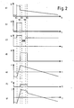
Die in Fig. 2 dargestellten Diagramme zeigen Spannungs- und Stromverläufe während einer Vertikal-Ablenkperiode. Dabei stellt das Diägramm a) die Ausgangsspannung einer Vertikal-Ablenkschaltung dar. Zwischen t1 und t2 erfolgt der Vertikal-Rücklauf. Durch die induktive Komponente der Ablenkspule und die schnellere Stromänderung während des Rücklaufs entsteht in an sich bekannter Weise zwischen t1 und t2 ein Spannungsimpuls. Während des Vertikal-Hinlaufs verläuft die Ausgangsspannung der Vertikal-Ablenkschaltung im wesentlichen zeitlinear.The diagrams shown in FIG. 2 show voltage and current profiles during a vertical deflection period. Diagram a) represents the output voltage of a vertical deflection circuit. The vertical return occurs between t1 and t2. Due to the inductive component of the deflection coil and the faster current change during the return, a voltage pulse is generated between t1 and t2 in a manner known per se. During the vertical run, the output voltage of the vertical deflection circuit is essentially time-linear.
Damit der gesamte Rucklaufbereich einschließlich eines möglicherweise gestörten Beginns des Hinlaufs des Kathodenstrahls ausgetastet wird, wird der Farbbildröhre 10 (Fig. 1) ein vertikalfrequenter Austastimpuls, wie in Diagramm b) dargestellt, zugeführt, welcher bis zum Zeitpunkt t3 dauert.In order that the entire return area, including a possibly disturbed start of the cathode beam run, is blanked out, the color picture tube 10 (FIG. 1) is supplied with a vertical frequency blanking pulse, as shown in diagram b), which lasts until time t3.
Bei der im Zusammenhang mit Fig. 1 erläterten Regelung wird im Anschluß an die Strahlaustastung mit Hilfe des in Diagramm c) gezeigten Impulses der Kathodenstrahl fur eine oder mehrere Zeilen freigegeben. Wird er für mehrere Zeilen freigegeben, so wird der Kathodenstrahl zwischen diesen Zeilen horizontalfrequent ausgetastet.In the control explained in connection with FIG. 1, the cathode ray is released for one or more lines following the beam blanking with the aid of the pulse shown in diagram c). If it is released for several lines, the cathode ray between these lines is blanked out horizontally.
Wie eingangs bereits erläutert, wird bei Fernsehgeräten üblicherweise das Raster so groß geschrieben, daß es über den Rahmen, welcher den Rand der Bildröhre abdeckt, hinausgeht. Der obere Rand des Rasters ist bei Fernsehgeräten also nicht sichtbar, so daß auch die fur die Strahlstrom-Regelung hellgetasteten Zeilen nicht störend in Erscheinung treten. Bei Monitoren, welche für Daten und graphische Darstellungen vorgesehen sind, wird jedoch das Raster kleiner geschrieben, so daß es ganz sichtbar ist. Um eine störende Helltastung der Meßzeilen fur die Strahlstrom-Regelung zu vermeiden, wird gemäß der vorliegenden Erfindung der Elektronenstrahl während dieser Zeilen zusätzlich abgelenkt. Dazu wird in einer an sich bekannten und daher nicht näher dargestellten Impulsformschaltung ein Impuls gemäß Diagramm d) erzeugt.As already explained at the beginning, the grid is usually written so large in television sets that it goes beyond the frame which covers the edge of the picture tube. The upper edge of the grid is therefore not visible in television sets, so that the lines that are blanked for the beam current control do not appear to be a nuisance either. In the case of monitors which are intended for data and graphic representations, however, the grid is written smaller so that it is completely visible. In order to avoid annoying blanking of the measurement lines for the beam current control, the electron beam is additionally deflected during these lines according to the present invention. For this purpose, a pulse according to diagram d) is generated in a pulse shaping circuit known per se and therefore not shown in detail.
Wegen der im wesentlichen durch die induktive Komponente der Vertikal-Ablenkspule bedingten Trägheit beginnt der Impuls bereits bei t2, also vor dem Beginn der Meßzeilen bei t3. Ferner liegt aus Sicherheitsgründen die Ruckflanke des Impulses bei t5 etwas später als das Ende der Meßzeilen bei t4.Because of the inertia essentially caused by the inductive component of the vertical deflection coil, the pulse begins at t2, ie before the start of the measuring lines at t3. Furthermore, the safety edge of the pulse at t5 is slightly later than the end of the measuring lines at t4 for safety reasons.
Diagramm e) stellt den Verlauf des Vertikal-Ablenkstroms bei der üblichen Rasterdarstellung dar. Aus dem in Diagramm d) gezeigten Spannungsimpuls wird der in Diagramm f) gezeigte Stromimpuls gewonnen, welcher dem üblichen Vertikal-Ablenkstrom überlagert wird, so daß der in Diagramm g) dargestellte Vertikal-Ablenkstrom entsteht. Zu Beginn des vertikalfrequenten Hinlaufs, also am oberen Rand des Rasters, springt der Strahl um einen vorgegebenen Wert nach oben, so daß die Zeilen, welche zur Strahlstrom-Regelung hellgetastet werden, an einer Stelle des Bildschirms geschrieben werden, welche durch einen Rahmen abgedeckt ist. Bei der Verwendung von Bildröhren ohne Rahmen kann der Strahl in einen Bereich abgelenkt werden, welcher nicht zum aktiven Bildschirm gehört, welcher also nicht mit Leuchtstoffen versehen ist.Diagram e) shows the course of the vertical deflection current in the usual raster representation. From the voltage pulse shown in diagram d), the current pulse shown in diagram f) is obtained, which is superimposed on the usual vertical deflection current, so that the one in diagram g) shown vertical deflection current arises. At the beginning of the vertical frequency traverse, that is to say at the upper edge of the grid, the beam jumps up by a predetermined value, so that the lines which are scanned for beam current control are written at a point on the screen which is covered by a frame . When using picture tubes without a frame, the beam can be deflected into an area that does not belong to the active screen, which is therefore not provided with phosphors.
Zum Zeitpunkt t5 springt der Strahl wieder in die vertikale Lage, welche durch die übliche sägezahnförmige Vertikal-Ablenkung gegeben ist. Der für die Darstellung der Videosignale vorgesehene Teil des Rasters bleibt also unverändert.At time t5, the beam jumps back into the vertical position, which is given by the usual sawtooth-shaped vertical deflection. The part of the grid provided for the display of the video signals therefore remains unchanged.
Bei der in Fig. 3 dargestellten Schaltungsanordnung ist an den Ausgang einer Vertikal-Ablenkschaltung 41 eine Reihenschaltung aus einer Vertikal-Ablenkspule 42, einem Kondensator 43 und einem Gegenkopplungs-Widerstand 44 angeschlossen. Vom Gegenkopplungs-Widerstand 44 ist eine Spannung abnehmbar, welche einem Steuereingang der Vertikal-Ablenkschaltung 41 zuführbar ist. Da die Spannung am Gegenkopplungs-Widerstand 44 dem durch die Verikal-Ablenkspule 42 fließenden Strom entspricht, kann in an sich bekannter Weise der Vertikal-Ablenkstrom derart geregelt werden, daß sich eine möglichst lineare Vertikal-Ablenkung auf dem Bildschirm ergibt.In the circuit arrangement shown in FIG. 3, a series circuit comprising a
Zur Durchfuhrung des erfindungsgemäßen Verfahrens wird der Vertikal-Ablenkschaltung 41 ein vertikalfrequenter Impuls entnommen und einem Impulsformer 45 zugeführt, an dessen Ausgang der in Fig. 2d) dargestellte Ansteuerimpuls ansteht. Dieser Impuls wird einem Verstärker 46 zugeführt, dessen Ausgang über einen Widerstand 47 mit dem Gegenkopplungspfad des Vertikal-Ablenkkreises verbunden ist. Während des Auftretens des Ansteuerimpulses wird durch den Verstärker 46 der Widerstand 47 dem Gegenkopplungs-Widerstand 44 parallelgeschaltet. Der sich ergebende Widerstandswert ist somit kleiner, wodurch die der Vertikal-Ablenkschaltung zugeführte Spannung bei gleichem Ablenkstrom ebenfalls kleiner wird. Der Vertikal-Ablenkschaltung wird sozusagen ein kleinerer Ablenkstrom vorgetäuscht, wodurch der Ablenkstrom während des Ansteuerimpulses entsprechend erhöht wird.To carry out the method according to the invention, a vertical-frequency pulse is taken from the
Fig. 4 zeigt eine andere Schaltung zur Durchführung des erfindungsgemäßen Verfahrens, bei welcher die Vertikal-Ablenkschaltung 41, die Vertikal-Ablenkspule 42, der Kondensator 43 und der Gegenkopplungs-Widerstand 44 in gleicher Weise wie bei der Schaltungsanordnung nach Fig. 3 angeordnet sind. Auch ein Impulsformer 45 dient zur Formung des Ansteuerimpulses für einen Verstärker 48, welcher jedoch nicht wie bei der Schaltungsanordnung nach Fig. 3 in den Gegenkopplungs-Kreis eingreift, sondern über einen Widerstand 49 der Ablenkspule 42 direkt zusätzlichen Strom zuführt.FIG. 4 shows another circuit for carrying out the method according to the invention, in which the
Im Rahmen des Fachmännischen sind Abwandlungen und Verbesserungen des erfindungsgemäßen Verfahrens und der Schaltungsanordnungen möglich. So können beispielsweise anstelle der Verstärker 46, 48 Halbleiterschalter vorgesehen werden. Auch die Überlagerung eines Stromimpulses mit dem sägezahnförmigen Ablenkstrom kann in anderer Weise, als in Fig. 4 dargestellt, erfolgen.Modifications and improvements of the method according to the invention and the circuit arrangements are possible within the scope of the expert. For example, semiconductor switches can be provided instead of the
Claims (9)
Applications Claiming Priority (2)
| Application Number | Priority Date | Filing Date | Title |
|---|---|---|---|
| DE19863610190 DE3610190A1 (en) | 1986-03-26 | 1986-03-26 | METHOD AND CIRCUIT ARRANGEMENTS FOR CONTROLLING THE WORKING POINT OF VIDEO POWER AMPLIFIERS |
| DE3610190 | 1986-03-26 |
Publications (2)
| Publication Number | Publication Date |
|---|---|
| EP0239014A2 true EP0239014A2 (en) | 1987-09-30 |
| EP0239014A3 EP0239014A3 (en) | 1990-02-21 |
Family
ID=6297317
Family Applications (1)
| Application Number | Title | Priority Date | Filing Date |
|---|---|---|---|
| EP87104064A Withdrawn EP0239014A3 (en) | 1986-03-26 | 1987-03-19 | Methods and circuit arrangements for controlling the operating point of final video stages |
Country Status (5)
| Country | Link |
|---|---|
| US (1) | US4763048A (en) |
| EP (1) | EP0239014A3 (en) |
| DE (1) | DE3610190A1 (en) |
| FI (1) | FI871305A (en) |
| ZA (1) | ZA872202B (en) |
Cited By (3)
| Publication number | Priority date | Publication date | Assignee | Title |
|---|---|---|---|---|
| EP0358987A2 (en) * | 1988-09-03 | 1990-03-21 | Deutsche Thomson-Brandt GmbH | Display apparatus with a cathode ray tube and a device for measuring the beam circuit |
| FR2649573A1 (en) * | 1989-07-07 | 1991-01-11 | Cirften Ilep | Process for controlling the device for producing scanned frames of a video set, means for implementing this process and sets equipped with these means |
| EP0542347A2 (en) * | 1991-11-13 | 1993-05-19 | Koninklijke Philips Electronics N.V. | Display device including a black level setting circuit |
Families Citing this family (2)
| Publication number | Priority date | Publication date | Assignee | Title |
|---|---|---|---|---|
| DE19746426A1 (en) * | 1997-10-21 | 1999-04-22 | Siemens Ag | Monitor with cathode ray tube |
| DE19856384A1 (en) | 1998-12-07 | 2000-06-08 | Siemens Ag | Method and circuit arrangement for regulating the operating point of a cathode ray tube |
Citations (6)
| Publication number | Priority date | Publication date | Assignee | Title |
|---|---|---|---|---|
| DE3034278A1 (en) * | 1980-09-11 | 1982-04-22 | Siemens AG, 1000 Berlin und 8000 München | Test process for visual display system - has control unit linked to monitor with facility for evaluating component performance |
| DE3047081A1 (en) * | 1980-12-13 | 1982-07-15 | Robert Bosch Gmbh, 7000 Stuttgart | DEFLECTION AMPLIFIER WITH CORRECTION OF NON-SYMMETRIC DISTORTIONS |
| EP0141256A2 (en) * | 1983-09-28 | 1985-05-15 | Hitachi, Ltd. | CRT picture display apparatus |
| EP0149730A2 (en) * | 1983-11-28 | 1985-07-31 | International Business Machines Corporation | CRT displays with variable format controls |
| EP0178734A2 (en) * | 1984-10-17 | 1986-04-23 | Philips Patentverwaltung GmbH | Image display tube control circuit |
| US4723158A (en) * | 1986-05-14 | 1988-02-02 | Zenith Electronics Corporation | Method and apparatus for performing scan line diagnostic testing in a video monitor during a last-line overscan of a normal display raster |
Family Cites Families (2)
| Publication number | Priority date | Publication date | Assignee | Title |
|---|---|---|---|---|
| JPS55118431A (en) * | 1979-03-05 | 1980-09-11 | Nippon Oil Co Ltd | Preparation of methyl t-butyl ether |
| US4340904A (en) * | 1980-12-24 | 1982-07-20 | General Electric Company | Automatic gray scale tracking system for cathode ray display devices |
-
1986
- 1986-03-26 DE DE19863610190 patent/DE3610190A1/en active Granted
-
1987
- 1987-01-29 US US07/008,310 patent/US4763048A/en not_active Expired - Fee Related
- 1987-03-19 EP EP87104064A patent/EP0239014A3/en not_active Withdrawn
- 1987-03-25 FI FI871305A patent/FI871305A/en not_active Application Discontinuation
- 1987-03-25 ZA ZA872202A patent/ZA872202B/en unknown
Patent Citations (6)
| Publication number | Priority date | Publication date | Assignee | Title |
|---|---|---|---|---|
| DE3034278A1 (en) * | 1980-09-11 | 1982-04-22 | Siemens AG, 1000 Berlin und 8000 München | Test process for visual display system - has control unit linked to monitor with facility for evaluating component performance |
| DE3047081A1 (en) * | 1980-12-13 | 1982-07-15 | Robert Bosch Gmbh, 7000 Stuttgart | DEFLECTION AMPLIFIER WITH CORRECTION OF NON-SYMMETRIC DISTORTIONS |
| EP0141256A2 (en) * | 1983-09-28 | 1985-05-15 | Hitachi, Ltd. | CRT picture display apparatus |
| EP0149730A2 (en) * | 1983-11-28 | 1985-07-31 | International Business Machines Corporation | CRT displays with variable format controls |
| EP0178734A2 (en) * | 1984-10-17 | 1986-04-23 | Philips Patentverwaltung GmbH | Image display tube control circuit |
| US4723158A (en) * | 1986-05-14 | 1988-02-02 | Zenith Electronics Corporation | Method and apparatus for performing scan line diagnostic testing in a video monitor during a last-line overscan of a normal display raster |
Cited By (5)
| Publication number | Priority date | Publication date | Assignee | Title |
|---|---|---|---|---|
| EP0358987A2 (en) * | 1988-09-03 | 1990-03-21 | Deutsche Thomson-Brandt GmbH | Display apparatus with a cathode ray tube and a device for measuring the beam circuit |
| EP0358987A3 (en) * | 1988-09-03 | 1990-04-04 | Deutsche Thomson-Brandt Gmbh | Display apparatus with a cathode ray tube and a device for measuring the beam circuit |
| FR2649573A1 (en) * | 1989-07-07 | 1991-01-11 | Cirften Ilep | Process for controlling the device for producing scanned frames of a video set, means for implementing this process and sets equipped with these means |
| EP0542347A2 (en) * | 1991-11-13 | 1993-05-19 | Koninklijke Philips Electronics N.V. | Display device including a black level setting circuit |
| EP0542347A3 (en) * | 1991-11-13 | 1995-04-12 | Philips Nv | Display device including a black level setting circuit |
Also Published As
| Publication number | Publication date |
|---|---|
| US4763048A (en) | 1988-08-09 |
| EP0239014A3 (en) | 1990-02-21 |
| FI871305A (en) | 1987-09-27 |
| DE3610190A1 (en) | 1987-10-01 |
| ZA872202B (en) | 1987-09-18 |
| FI871305A0 (en) | 1987-03-25 |
| DE3610190C2 (en) | 1989-10-12 |
Similar Documents
| Publication | Publication Date | Title |
|---|---|---|
| DE2252181C3 (en) | Video amplifier for a color television monitor | |
| AT391767B (en) | CIRCUIT TO SAMPLE AN INPUT SIGNAL | |
| DE3014984C2 (en) | Circuit arrangement for the automatic regulation of the blanking current level of a picture tube | |
| DE2618531C2 (en) | Correction circuitry for a television tube | |
| DE3138226C2 (en) | ||
| DE2622829B2 (en) | Service circuit for a color television set | |
| AT390859B (en) | CIRCUIT ARRANGEMENT FOR THE AUTOMATIC CONTROL OF THE BLACK CURRENT LEVEL OF A PICTURE TUBE | |
| DE2720374A1 (en) | AMPLIFIER WITH AUTOMATIC GAIN CONTROL | |
| DE2137567C3 (en) | Electronic amplifier circuit for supplying a load with a voltage which can assume exceptionally high values | |
| DE2946358C2 (en) | ||
| DE1085914B (en) | Transistor circuit for supplying saw tooth currents to a load resistor | |
| AT390537B (en) | CIRCUIT FOR GENERATING DRIVER SIGNALS FOR A PICTURE TUBE AND FOR CONTROLLING THE BLACK LEVEL CURRENT | |
| DE965908C (en) | Circuit for generating control voltage, especially in television receivers | |
| EP0239014A2 (en) | Methods and circuit arrangements for controlling the operating point of final video stages | |
| DE2335763C2 (en) | Aperture correction circuit | |
| DE2111217C3 (en) | Vertical deflection circuit with pincushion distortion correction circuit | |
| DE2812407A1 (en) | CIRCUIT ARRANGEMENT FOR CONTROLLING A TELEVISION RECORDING EAR | |
| DE3339195C2 (en) | ||
| DE918211C (en) | Device for stabilizing television characters composed of synchronization characters and pixel characters | |
| DE1270079B (en) | Deflection circuit for a color television camera with at least two image pickup tubes | |
| DE1237699B (en) | Circuit arrangement for generating an adjustable DC voltage for a cathode ray tube | |
| DE1038106B (en) | Synchronizing device for television receivers | |
| DE2044352C3 (en) | Circuit for blanking color television signals | |
| DE955154C (en) | Circuit for interference signal suppression in television amplifiers | |
| DE2235905A1 (en) | BILLING FOR TELEVISION RECEIVER |
Legal Events
| Date | Code | Title | Description |
|---|---|---|---|
| PUAI | Public reference made under article 153(3) epc to a published international application that has entered the european phase |
Free format text: ORIGINAL CODE: 0009012 |
|
| AK | Designated contracting states |
Kind code of ref document: A2 Designated state(s): DE FR IT SE |
|
| PUAL | Search report despatched |
Free format text: ORIGINAL CODE: 0009013 |
|
| AK | Designated contracting states |
Kind code of ref document: A3 Designated state(s): DE FR IT SE |
|
| 17P | Request for examination filed |
Effective date: 19900329 |
|
| STAA | Information on the status of an ep patent application or granted ep patent |
Free format text: STATUS: THE APPLICATION IS DEEMED TO BE WITHDRAWN |
|
| 18D | Application deemed to be withdrawn |
Effective date: 19911003 |
|
| RIN1 | Information on inventor provided before grant (corrected) |
Inventor name: SCHILLER, WILFRIED |