EP0238720A1 - Floor maintenance device drive system - Google Patents
Floor maintenance device drive system Download PDFInfo
- Publication number
- EP0238720A1 EP0238720A1 EP86116487A EP86116487A EP0238720A1 EP 0238720 A1 EP0238720 A1 EP 0238720A1 EP 86116487 A EP86116487 A EP 86116487A EP 86116487 A EP86116487 A EP 86116487A EP 0238720 A1 EP0238720 A1 EP 0238720A1
- Authority
- EP
- European Patent Office
- Prior art keywords
- pad
- floor
- driver member
- contact
- removably mounting
- Prior art date
- Legal status (The legal status is an assumption and is not a legal conclusion. Google has not performed a legal analysis and makes no representation as to the accuracy of the status listed.)
- Granted
Links
- 238000012423 maintenance Methods 0.000 title claims abstract description 25
- 230000003292 diminished effect Effects 0.000 abstract 1
- 239000000872 buffer Substances 0.000 description 4
- 238000010276 construction Methods 0.000 description 3
- 239000000463 material Substances 0.000 description 3
- 229910000831 Steel Inorganic materials 0.000 description 1
- 229910052782 aluminium Inorganic materials 0.000 description 1
- XAGFODPZIPBFFR-UHFFFAOYSA-N aluminium Chemical compound [Al] XAGFODPZIPBFFR-UHFFFAOYSA-N 0.000 description 1
- 230000006835 compression Effects 0.000 description 1
- 238000007906 compression Methods 0.000 description 1
- 239000006260 foam Substances 0.000 description 1
- 239000003292 glue Substances 0.000 description 1
- 230000001939 inductive effect Effects 0.000 description 1
- 238000003780 insertion Methods 0.000 description 1
- 230000037431 insertion Effects 0.000 description 1
- 229910052751 metal Inorganic materials 0.000 description 1
- 239000002184 metal Substances 0.000 description 1
- 239000007769 metal material Substances 0.000 description 1
- 238000005498 polishing Methods 0.000 description 1
- 239000010959 steel Substances 0.000 description 1
Images

Classifications
-
- A—HUMAN NECESSITIES
- A47—FURNITURE; DOMESTIC ARTICLES OR APPLIANCES; COFFEE MILLS; SPICE MILLS; SUCTION CLEANERS IN GENERAL
- A47L—DOMESTIC WASHING OR CLEANING; SUCTION CLEANERS IN GENERAL
- A47L11/00—Machines for cleaning floors, carpets, furniture, walls, or wall coverings
- A47L11/40—Parts or details of machines not provided for in groups A47L11/02 - A47L11/38, or not restricted to one of these groups, e.g. handles, arrangements of switches, skirts, buffers, levers
- A47L11/4036—Parts or details of the surface treating tools
- A47L11/4038—Disk shaped surface treating tools
-
- A—HUMAN NECESSITIES
- A47—FURNITURE; DOMESTIC ARTICLES OR APPLIANCES; COFFEE MILLS; SPICE MILLS; SUCTION CLEANERS IN GENERAL
- A47L—DOMESTIC WASHING OR CLEANING; SUCTION CLEANERS IN GENERAL
- A47L11/00—Machines for cleaning floors, carpets, furniture, walls, or wall coverings
- A47L11/02—Floor surfacing or polishing machines
- A47L11/10—Floor surfacing or polishing machines motor-driven
- A47L11/14—Floor surfacing or polishing machines motor-driven with rotating tools
- A47L11/16—Floor surfacing or polishing machines motor-driven with rotating tools the tools being disc brushes
- A47L11/164—Parts or details of the brushing tools
-
- A—HUMAN NECESSITIES
- A47—FURNITURE; DOMESTIC ARTICLES OR APPLIANCES; COFFEE MILLS; SPICE MILLS; SUCTION CLEANERS IN GENERAL
- A47L—DOMESTIC WASHING OR CLEANING; SUCTION CLEANERS IN GENERAL
- A47L11/00—Machines for cleaning floors, carpets, furniture, walls, or wall coverings
- A47L11/40—Parts or details of machines not provided for in groups A47L11/02 - A47L11/38, or not restricted to one of these groups, e.g. handles, arrangements of switches, skirts, buffers, levers
- A47L11/4063—Driving means; Transmission means therefor
- A47L11/4069—Driving or transmission means for the cleaning tools
Definitions
- the present invention relates to a floor maintenance device, more particularly, a floor maintenance device including a rotating pad for contact with a floor surface.
- the floor maintenance device of the type described by the present invention includes a driver system and a rotating pad.
- the pad may be used for polishing the floor surface to give a shiny or glossy appearance.
- the use of high speed buffers or burnishers has become accepted due to the ability of these high speed machines to give floors a very high sheen or gloss.
- the high rotary speed of the pad provides the desired sheen or gloss to the floor, it also results in the need for more frequent replacement of buffer or scrubber pads on the bottom of the floor maintenance device. Additionally, if the pad is not placed properly with respect to the driver, vibrations may be transmitted to the operator, which; if severe, may render the buffer unusable.
- a floor maintenance device includes a drive system which rotates a pad against a floor.
- the drive system includes a driver member which has several pressure sensitive contact pads affixed to its underside.
- the driver member is in contact with a pad holder having outwardly extending flange and a central portion.
- the central portion of the pad holder fits within the driver member and is maintained in contact therewith by compatible pressure sensitive contact pads which are affixed to the topside of the pad holder.
- On the underside of the pad holder are additional pressure sensitive contact pads which hold the rotating floor pad in place.
- the floor maintenance device of the present invention includes a drive system for a rotating pad which has three essential components. These three components are a driver member which is connected to a rotary driver such as an electric motor, gas engine, air motor or hydraulic motor; a pad holder which is attached to the driver member both transmit rotating force to the pad and also holds the floor maintenance pad in position and thirdly; a rotating pad grip face and retainer which mechanically mounts the rotating pad to the driver member.
- a driver member which is connected to a rotary driver such as an electric motor, gas engine, air motor or hydraulic motor
- a pad holder which is attached to the driver member both transmit rotating force to the pad and also holds the floor maintenance pad in position and thirdly
- a rotating pad grip face and retainer which mechanically mounts the rotating pad to the driver member.
- Motor 12 imparts rotating power to shaft 14 which fits within shaft receptacle 16.
- a key 22 may be used and additionally a washer 18 and bolt 20 may also be used to attach driver member 24 to shaft 14.
- driver member 24 in the preferred embodiment is a generally square or box shaped device consisting of a plate 25 which has four depending sides 32.
- Plate 25 has a top 26 and an underside 28.
- pads 30 On the underside 28 of the plate 25 are mounted four pads 30. While four pads 30 are shown in the preferred embodiment, it will be understood that a continuous pad or any number of pads may be used in place of the four pads designated by reference numeral 30.
- Figure 2 A comparison of Figure 2 to Figure 1 shows the four pads 30 in their position on the underside 28 of driver member 24. Addition strictlyally, Figure 2 illustrates groove 29 whose function will be explained later in conjunction with the use of retainer 62.
- Pads 30 are of the type which are commonly known as VELCRO® fasteners. Such VELCRO® fasteners may be more generically termed hook and loop pressure contact attachment systems. Pads 30 may either be of the hook variety or of the loop variety. Corresponding pressure sensitive pads 40 to pads 30 are located on pad holder 34 whose construction and function will now be explained.
- pad holder 34 consists of an outwardly extending flange 36 and a central portion 38.
- the central portion 38 is constructed so as to fit within driver member 24. While a square or rectangular arrangement is shown in the preferred embodiment it will be understood that the key function of the meeting of driver member 24 and central portion 38 of pad holder 34 is to transmit drive forces to pad holder 34. Any shape which may accomplish this function is suitable. Accordingly, a polygon shape may be used in place of the square shape shown in the preferred embodiment.
- the central portion 38 of pad holder 34 includes an aperture 42 in in its midst. Also included on central portion 38 of pad holder 34 are pads 40. These pads 40 correspond in position to pads 30 of driver member 24. When central portion 38 of pad holder 34 is inserted into driver member 24, pads 40 engage pads 30. Because of the hook and loop pressure contact system which characterize pads 30 and 40 in the preferred embodiment, a mechanical attachment between pads 30 and 40 will take place. While it is understood that pads 30 and 40 are shown as VELCRO® pads in the preferred embodiment, any type of pressure sensitive contact pads may be used in place of the VELCRO® fasteners. Specifically, pressure sensitive glued pads or magnetic pads are examples of pads which may be substituted for the VELCRO® pads shown in the preferred embodiment.
- pad grip face 50 Figure 1
- pad grip face 50 is shown as consisting of four segments 51 in the preferred embodiment, it will be understood that pad grip face 50 may be constructed of any number of segments.
- pad grip face 50 Further details of the construction of pad grip face 50 may be had by reference to Figure 3 wherein it is shown that the underside or bottom 54 of pad grip face 50 is characterized by a similar type of hook and loop type fasteners as used on the bottom 48 of pad holder 34.
- pad 58 is in contact with the underside 54 of pad grip face 50. Because of the fibrous or rigid foam nature of pad 58 the hook and loop contact attachment system 55 on the bottom of pad grip face 50 will mechanically engage pad 58.
- Retainer 62 fits within hole 60 of pad 58 and passes through hole 60 of pad 58, hole 56 and pad grip face 50, aperture 42 in pad holder 34 and eventually mounts in groove 29 ( Figure 2) of driver member 24. Accordingly, central portion 70 of retainer 62 is of sufficient length to mount pad 58 to driver member 24. This mounting is accomplished by engagement of retaining ring 68 in groove 29. Pad 58 is held in place by the force of flange 64 against the underside of pad 58.
- retainer 62 When it is desired to remove or replace pad 58 because of excessive wear or dirt formed on the underside of pad 58, retainer 62 is removed. This is accomplished by compressing the size of retainer 62 utilizing split 66 in retainer 62 to reduce the circumference of retainer 62. Accordingly, retaining ring 68 may then be removed from groove 29 in driver member 24. With the removal of retainer 62, it is now possible to remove pad 58 and pad holder 34. The use of pressure sensitive contact pads 40 and 30 simplifies this operation as it is then merely necessary to peel pads 40 away from pads 30.
- pad grip face 50 and pad holder 34 are removed from driver member 24 it is then possible to disassemble pad 58 from pad holder 34. This is easily accomplished by the peeling away of pad 58 from pad grip face 50. A new pad 58 may then be replaced on pad grip face 50 and the device reassembled.
- the VELCRO® fasteners allow pad 58 to be placed concentrically on pad grip face 50 and pad holder 34. Once this has been accomplished, the final step involves the insertion of retainer 62 through hole 60 in pad 58, hole 56 in pad grip face 50, aperture 42 in pad holder 34 and engagement of retaining ring within groove 24 of driver member 24.
- the use of VELCRO® fasteners prevents misalignment or lack of concentricity of the rotating parts during reassembly.
- the floor maintenance device of the present invention a system for providing rotating force to a floor maintenance pad which may be easily disassembled and reassembled without inducing significant vibrations to the user.
- the driver member of the present invention may be manufactured from steel, aluminum or any rigid material which will withstand rotating drive forces commonly associated with floor maintenance devices.
- pads 30 may be made from VELCRO® , glue or magnets.
- Pad holder 34 may be constructed of metal, plastic or any rigid material which has some flexibility but will withstand the drive forces and high speeds normally associated with a floor polisher or burnisher.
- pads 40 may also be VELCRO® or any other convenient type of pressure sensitive contact system which will provide the peelable contact necessary for rapid disassembly and reassembly.
- Pad grip face 50 may be constructed of any suitable material which will allow the attachment by hook and loop means.
- Retainer 62 may be made of any suitable plastic or metallic material which will provide sufficient compressive forces to hold pad 58 in place and retain its shape after compression at split 66 so as to hold pad 58 in place when mated with groove 29 in driver member 24.
Landscapes
- Floor Finish (AREA)
Abstract
Description
- The present invention relates to a floor maintenance device, more particularly, a floor maintenance device including a rotating pad for contact with a floor surface.
- The floor maintenance device of the type described by the present invention includes a driver system and a rotating pad. The pad may be used for polishing the floor surface to give a shiny or glossy appearance. In recent years, the use of high speed buffers or burnishers has become accepted due to the ability of these high speed machines to give floors a very high sheen or gloss. While the high rotary speed of the pad provides the desired sheen or gloss to the floor, it also results in the need for more frequent replacement of buffer or scrubber pads on the bottom of the floor maintenance device. Additionally, if the pad is not placed properly with respect to the driver, vibrations may be transmitted to the operator, which; if severe, may render the buffer unusable. Replacement of pads in high speed buffers is difficult because the pad is typically attached to the bottom of the driver by mechanical fasteners. Such a rigid attachment means is used in an effort to reduce vibration. Each time a pad becomes dirty or worn out, the mechanical fasteners must be removed and attachment means reassembled in order to replace the pad. If not done carefully, vibrations will result which require disassembly and remounting of the pad. There is therefore a need in the art to provide a floor maintenance device which provides a high speed pad driving system adapted for quick replacement of floor maintenance pads and which will also mount the pad so that vibrations will be kept to a minimum.
- A floor maintenance device includes a drive system which rotates a pad against a floor. The drive system includes a driver member which has several pressure sensitive contact pads affixed to its underside. The driver member is in contact with a pad holder having outwardly extending flange and a central portion. The central portion of the pad holder fits within the driver member and is maintained in contact therewith by compatible pressure sensitive contact pads which are affixed to the topside of the pad holder. On the underside of the pad holder are additional pressure sensitive contact pads which hold the rotating floor pad in place. Once the pad, the pad holder and driver member have been aligned by use of the pressure sensitive contact pads, a retainer which extends through the center of the floor pad and the pad holder is used to mechanically mount the pad to the driver member.
- A better understanding of the floor maintenance device and drive system therefor of the present invention may be had by reference to the drawings wherein;
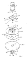
- Figure 1 is an exploded view of a drive system for a floor maintenance device;
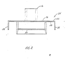
- Figure 2 is a side elevational view partially in section of the driver member as shown in Figure 1;
- Figure 3 is an end view of the pad holder; and
- Figure 4 is a side view of the pad gripper face.
- The floor maintenance device of the present invention includes a drive system for a rotating pad which has three essential components. These three components are a driver member which is connected to a rotary driver such as an electric motor, gas engine, air motor or hydraulic motor; a pad holder which is attached to the driver member both transmit rotating force to the pad and also holds the floor maintenance pad in position and thirdly; a rotating pad grip face and retainer which mechanically mounts the rotating pad to the driver member. A better understanding of the inter-relationship of these three parts may be had by reference to Figure 1 wherein
motor 12 is shown abovedriver member 24. As previously mentioned,motor 12 may be an electric motor, a gas engine, or a hydraulic or air motor. Additionally, other types of power systems which impart rotating power to a shaft may be used.Motor 12 imparts rotating power toshaft 14 which fits withinshaft receptacle 16. To assure a tight fit betweenshaft 14 and shaft receptacle 16 akey 22 may be used and additionally awasher 18 andbolt 20 may also be used to attachdriver member 24 toshaft 14. - As shown in Figures 1 and 2
driver member 24 in the preferred embodiment is a generally square or box shaped device consisting of aplate 25 which has four dependingsides 32.Plate 25 has atop 26 and anunderside 28. On theunderside 28 of theplate 25 are mounted fourpads 30. While fourpads 30 are shown in the preferred embodiment, it will be understood that a continuous pad or any number of pads may be used in place of the four pads designated byreference numeral 30. - A comparison of Figure 2 to Figure 1 shows the four
pads 30 in their position on theunderside 28 ofdriver member 24. Additionally, Figure 2 illustratesgroove 29 whose function will be explained later in conjunction with the use ofretainer 62. -
Pads 30 are of the type which are commonly known as VELCRO® fasteners. Such VELCRO® fasteners may be more generically termed hook and loop pressure contact attachment systems.Pads 30 may either be of the hook variety or of the loop variety. Corresponding pressuresensitive pads 40 topads 30 are located onpad holder 34 whose construction and function will now be explained. - As best shown by Figures 1 and 3
pad holder 34 consists of an outwardly extendingflange 36 and acentral portion 38. Thecentral portion 38 is constructed so as to fit withindriver member 24. While a square or rectangular arrangement is shown in the preferred embodiment it will be understood that the key function of the meeting ofdriver member 24 andcentral portion 38 ofpad holder 34 is to transmit drive forces topad holder 34. Any shape which may accomplish this function is suitable. Accordingly, a polygon shape may be used in place of the square shape shown in the preferred embodiment. - The
central portion 38 ofpad holder 34 includes anaperture 42 in in its midst. Also included oncentral portion 38 ofpad holder 34 arepads 40. Thesepads 40 correspond in position to pads 30 ofdriver member 24. Whencentral portion 38 ofpad holder 34 is inserted intodriver member 24,pads 40 engagepads 30. Because of the hook and loop pressure contact system which characterizepads pads pads - Additional details of construction of
pad holder 34 are shown in Figure 2. Specifically, on the bottom 48 ofpad holder 34, are additional VELCRO® or hook and loop type fasteners. This fastener system is designed to engage pad grip face 50 (Figure 1). Whilepad grip face 50 is shown as consisting of four segments 51 in the preferred embodiment, it will be understood thatpad grip face 50 may be constructed of any number of segments. - Further details of the construction of
pad grip face 50 may be had by reference to Figure 3 wherein it is shown that the underside orbottom 54 ofpad grip face 50 is characterized by a similar type of hook and loop type fasteners as used on the bottom 48 ofpad holder 34. - As may be further seen in Figure 1, pad 58 is in contact with the
underside 54 ofpad grip face 50. Because of the fibrous or rigid foam nature of pad 58 the hook and loopcontact attachment system 55 on the bottom ofpad grip face 50 will mechanically engage pad 58. -
Retainer 62 fits withinhole 60 of pad 58 and passes throughhole 60 of pad 58,hole 56 andpad grip face 50,aperture 42 inpad holder 34 and eventually mounts in groove 29 (Figure 2) ofdriver member 24. Accordingly,central portion 70 ofretainer 62 is of sufficient length to mount pad 58 todriver member 24. This mounting is accomplished by engagement of retainingring 68 ingroove 29. Pad 58 is held in place by the force offlange 64 against the underside of pad 58. - When it is desired to remove or replace pad 58 because of excessive wear or dirt formed on the underside of pad 58,
retainer 62 is removed. This is accomplished by compressing the size ofretainer 62 utilizing split 66 inretainer 62 to reduce the circumference ofretainer 62. Accordingly, retainingring 68 may then be removed fromgroove 29 indriver member 24. With the removal ofretainer 62, it is now possible to remove pad 58 andpad holder 34. The use of pressuresensitive contact pads pads 40 away frompads 30. - After the combination of pad 58,
pad grip face 50 andpad holder 34 are removed fromdriver member 24 it is then possible to disassemble pad 58 frompad holder 34. This is easily accomplished by the peeling away of pad 58 frompad grip face 50. A new pad 58 may then be replaced onpad grip face 50 and the device reassembled. - It is upon reassembly that the benefit of the VELCRO® fasteners to reducing vibration becomes most apparent. The VELCRO® fasteners allow pad 58 to be placed concentrically on
pad grip face 50 andpad holder 34. Once this has been accomplished, the final step involves the insertion ofretainer 62 throughhole 60 in pad 58,hole 56 inpad grip face 50,aperture 42 inpad holder 34 and engagement of retaining ring withingroove 24 ofdriver member 24. The use of VELCRO® fasteners prevents misalignment or lack of concentricity of the rotating parts during reassembly. - There is thereby provided by the floor maintenance device of the present invention, a system for providing rotating force to a floor maintenance pad which may be easily disassembled and reassembled without inducing significant vibrations to the user.
- The driver member of the present invention may be manufactured from steel, aluminum or any rigid material which will withstand rotating drive forces commonly associated with floor maintenance devices. As previously stated,
pads 30 may be made from VELCRO® , glue or magnets.Pad holder 34 may be constructed of metal, plastic or any rigid material which has some flexibility but will withstand the drive forces and high speeds normally associated with a floor polisher or burnisher. As previously stated,pads 40 may also be VELCRO® or any other convenient type of pressure sensitive contact system which will provide the peelable contact necessary for rapid disassembly and reassembly. Pad grip face 50 may be constructed of any suitable material which will allow the attachment by hook and loop means.Retainer 62 may be made of any suitable plastic or metallic material which will provide sufficient compressive forces to hold pad 58 in place and retain its shape after compression atsplit 66 so as to hold pad 58 in place when mated withgroove 29 indriver member 24. - It is to be understood that while the floor maintenance device of the present invention has been described in accordance with the preferred embodiment, the scope of the present invention is to be determined only by a reading of the claims by one of ordinary skill in the art giving reference to the specification and figures.
Claims (18)
a floor pad or the like;
means for rotating said floor pad or the like;
a driver member constructed and arranged to driveably engage said means for rotating said floor plan or the like;
at least one pressure sensitive contact pad affixed to the underside of said driver member; and
a pad holder, said pad holder having:
an outwardly extending flange;
a central portion constructed and arranged to driveably engage said driver member;
at least one pressure sensitive contact pad affixed to the topside of said central portion for engagement with said pressure sensitive pad affixed to the underside of said driver member; and
means for driveably and removably mounting a floor pad or the like located on the underside of said outwardly extending flange;
whereby the floor pad may be driven in a rotary fashion and easily replaced.
a shaft;
means for rotating said shaft;
a driver member constructed and arranged to rotate with said shaft;
at least one pressure sensitive contact pad affixed to the underside of said driver member; and
a pad holder, said pad holder having:
an outwardly extending flange;
a central portion constructed and arranged to driveably engage said driver member;
at least one pressure sensitive contact pad affixed to the topside of said central portion for engagement with said pressure sensitive pad affixed to the underside of said driver member; and
means for driveably and removably mounting a floor pad or the like located on the underside of said outwardly extending flange;
whereby the rotating floor pad may be driven in a rotary fashion and easily replaced.
a driver member;
at least one contact pad affixed to the underside of said driver member;
at least one contact pad affixed to the holder for the floor pad or the like for engagement with said contact pad affixed to the underside of said driver member;
said contact pads remaining attached to each other when brought into contact with the other;
whereby said pad holder is positioned and removably mounted in said driver member by said contact pads.
Applications Claiming Priority (2)
| Application Number | Priority Date | Filing Date | Title |
|---|---|---|---|
| US83248586A | 1986-02-24 | 1986-02-24 | |
| US832485 | 1986-02-24 |
Publications (2)
| Publication Number | Publication Date |
|---|---|
| EP0238720A1 true EP0238720A1 (en) | 1987-09-30 |
| EP0238720B1 EP0238720B1 (en) | 1990-05-23 |
Family
ID=25261788
Family Applications (1)
| Application Number | Title | Priority Date | Filing Date |
|---|---|---|---|
| EP19860116487 Expired EP0238720B1 (en) | 1986-02-24 | 1986-11-27 | Floor maintenance device drive system |
Country Status (2)
| Country | Link |
|---|---|
| EP (1) | EP0238720B1 (en) |
| DE (1) | DE3671359D1 (en) |
Cited By (2)
| Publication number | Priority date | Publication date | Assignee | Title |
|---|---|---|---|---|
| US20140237743A1 (en) * | 2013-02-27 | 2014-08-28 | Tennant Company | Cleaning head assemblies having touch-free attachment and alignment technology |
| US10251524B2 (en) | 2013-02-27 | 2019-04-09 | Tennant Company | Cleaning head assemblies having touch-free attachment and alignment technology |
Citations (4)
| Publication number | Priority date | Publication date | Assignee | Title |
|---|---|---|---|---|
| US2911661A (en) * | 1958-08-08 | 1959-11-10 | Raymond W Bales | Floor waxing device |
| FR1259313A (en) * | 1960-06-10 | 1961-04-21 | Floor polish machine with rotating concentric brushes | |
| DE1898046U (en) * | 1964-03-25 | 1964-08-06 | Kicherer Fakir Werk | DEVICE FOR FASTENING SANDING SHEETS TO BEING MACHINES |
| US3655444A (en) * | 1969-08-07 | 1972-04-11 | C T & R E Inc | Methods and means for treating surfaces |
-
1986
- 1986-11-27 EP EP19860116487 patent/EP0238720B1/en not_active Expired
- 1986-11-27 DE DE8686116487T patent/DE3671359D1/en not_active Expired - Fee Related
Patent Citations (4)
| Publication number | Priority date | Publication date | Assignee | Title |
|---|---|---|---|---|
| US2911661A (en) * | 1958-08-08 | 1959-11-10 | Raymond W Bales | Floor waxing device |
| FR1259313A (en) * | 1960-06-10 | 1961-04-21 | Floor polish machine with rotating concentric brushes | |
| DE1898046U (en) * | 1964-03-25 | 1964-08-06 | Kicherer Fakir Werk | DEVICE FOR FASTENING SANDING SHEETS TO BEING MACHINES |
| US3655444A (en) * | 1969-08-07 | 1972-04-11 | C T & R E Inc | Methods and means for treating surfaces |
Cited By (8)
| Publication number | Priority date | Publication date | Assignee | Title |
|---|---|---|---|---|
| US20140237743A1 (en) * | 2013-02-27 | 2014-08-28 | Tennant Company | Cleaning head assemblies having touch-free attachment and alignment technology |
| WO2014134091A1 (en) * | 2013-02-27 | 2014-09-04 | Tennant Company | Cleaning head assemblies having touch-free attachment and alignment technology |
| CN105142483A (en) * | 2013-02-27 | 2015-12-09 | 坦南特公司 | Cleaning head assemblies having touch-free attachment and alignment technology |
| JP2016508424A (en) * | 2013-02-27 | 2016-03-22 | テンナント カンパニー | Cleaning head assembly with touch-free mounting and alignment technology |
| AU2014223616B2 (en) * | 2013-02-27 | 2016-04-28 | Tennant Company | Cleaning head assemblies having touch-free attachment and alignment technology |
| AU2014223616C1 (en) * | 2013-02-27 | 2016-11-24 | Tennant Company | Cleaning head assemblies having touch-free attachment and alignment technology |
| US10226159B2 (en) * | 2013-02-27 | 2019-03-12 | Tennant Company | Cleaning head assemblies having touch-free attachment and alignment technology |
| US10251524B2 (en) | 2013-02-27 | 2019-04-09 | Tennant Company | Cleaning head assemblies having touch-free attachment and alignment technology |
Also Published As
| Publication number | Publication date |
|---|---|
| DE3671359D1 (en) | 1990-06-28 |
| EP0238720B1 (en) | 1990-05-23 |
Similar Documents
| Publication | Publication Date | Title |
|---|---|---|
| CA1228958A (en) | Pull-apart mounting hub | |
| US5170595A (en) | Pull tab for velcro backed marble grinding pad and method for removal | |
| US6342002B1 (en) | Structure of a wax-polishing machine | |
| EP0904896A3 (en) | Rotary grinding jig | |
| JP2001287145A (en) | Hand-held electric grinder and abrasive support for use in the grinding plate of the hand-held electric grinder | |
| CN110116354B (en) | Hand-held and hand-guided power tool and work element for the same in the form of a back cushion | |
| CA2717530C (en) | Orbital smoothing device | |
| JP2001522731A (en) | Backup pad for abrasive products and method of use | |
| US4242839A (en) | High-speed power tool | |
| US5309682A (en) | Hand held power tool with working disc | |
| FR2644370B1 (en) | MACHINE FOR CONDITIONING AND / OR MAINTENANCE OF FLOORS PROVIDED WITH A ROTARY TOOL | |
| AU588491B2 (en) | Improvements in high speed floor burnishing machine | |
| EP0361505A3 (en) | Surface working pad assemmbly | |
| EP0238720B1 (en) | Floor maintenance device drive system | |
| US6105197A (en) | Centering system for buffing pad | |
| US20070077873A1 (en) | Planetary drive heads for grinding/polishing pads | |
| WO2000054936A1 (en) | Surface finishing machine | |
| US9089945B2 (en) | Orbital smoothing device | |
| CN221495363U (en) | Metal sample polisher | |
| EP0745019B1 (en) | System for clamping replaceable abrasive discs to the sides of plates on rotating dressers | |
| CA2253065A1 (en) | Disk locking device | |
| WO2003032799A9 (en) | Apparatus for treating a floor surface | |
| EP0182178A1 (en) | Method of and machine for treating an uneven floor surface | |
| WO1991004701A1 (en) | Floor polishing machine | |
| EP0719616A1 (en) | Improved oscillating hand tool |
Legal Events
| Date | Code | Title | Description |
|---|---|---|---|
| PUAI | Public reference made under article 153(3) epc to a published international application that has entered the european phase |
Free format text: ORIGINAL CODE: 0009012 |
|
| AK | Designated contracting states |
Kind code of ref document: A1 Designated state(s): DE GB IT |
|
| 17P | Request for examination filed |
Effective date: 19880315 |
|
| 17Q | First examination report despatched |
Effective date: 19890825 |
|
| GRAA | (expected) grant |
Free format text: ORIGINAL CODE: 0009210 |
|
| AK | Designated contracting states |
Kind code of ref document: B1 Designated state(s): DE GB IT |
|
| REF | Corresponds to: |
Ref document number: 3671359 Country of ref document: DE Date of ref document: 19900628 |
|
| ITF | It: translation for a ep patent filed | ||
| RAP2 | Party data changed (patent owner data changed or rights of a patent transferred) |
Owner name: CLARKE INDUSTRIES, INC. |
|
| PG25 | Lapsed in a contracting state [announced via postgrant information from national office to epo] |
Ref country code: GB Effective date: 19901127 |
|
| PLBE | No opposition filed within time limit |
Free format text: ORIGINAL CODE: 0009261 |
|
| STAA | Information on the status of an ep patent application or granted ep patent |
Free format text: STATUS: NO OPPOSITION FILED WITHIN TIME LIMIT |
|
| 26N | No opposition filed | ||
| GBPC | Gb: european patent ceased through non-payment of renewal fee | ||
| PG25 | Lapsed in a contracting state [announced via postgrant information from national office to epo] |
Ref country code: DE Effective date: 19910801 |
|
| PG25 | Lapsed in a contracting state [announced via postgrant information from national office to epo] |
Ref country code: IT Free format text: LAPSE BECAUSE OF NON-PAYMENT OF DUE FEES;WARNING: LAPSES OF ITALIAN PATENTS WITH EFFECTIVE DATE BEFORE 2007 MAY HAVE OCCURRED AT ANY TIME BEFORE 2007. THE CORRECT EFFECTIVE DATE MAY BE DIFFERENT FROM THE ONE RECORDED. Effective date: 20051127 |