EP0238318B1 - Track access control system for magnetic disk system - Google Patents
Track access control system for magnetic disk system Download PDFInfo
- Publication number
- EP0238318B1 EP0238318B1 EP87302307A EP87302307A EP0238318B1 EP 0238318 B1 EP0238318 B1 EP 0238318B1 EP 87302307 A EP87302307 A EP 87302307A EP 87302307 A EP87302307 A EP 87302307A EP 0238318 B1 EP0238318 B1 EP 0238318B1
- Authority
- EP
- European Patent Office
- Prior art keywords
- track
- servo
- magnetic disc
- offset
- tracks
- Prior art date
- Legal status (The legal status is an assumption and is not a legal conclusion. Google has not performed a legal analysis and makes no representation as to the accuracy of the status listed.)
- Expired - Lifetime
Links
Images








Classifications
-
- G—PHYSICS
- G11—INFORMATION STORAGE
- G11B—INFORMATION STORAGE BASED ON RELATIVE MOVEMENT BETWEEN RECORD CARRIER AND TRANSDUCER
- G11B5/00—Recording by magnetisation or demagnetisation of a record carrier; Reproducing by magnetic means; Record carriers therefor
- G11B5/48—Disposition or mounting of heads or head supports relative to record carriers ; arrangements of heads, e.g. for scanning the record carrier to increase the relative speed
- G11B5/58—Disposition or mounting of heads or head supports relative to record carriers ; arrangements of heads, e.g. for scanning the record carrier to increase the relative speed with provision for moving the head for the purpose of maintaining alignment of the head relative to the record carrier during transducing operation, e.g. to compensate for surface irregularities of the latter or for track following
- G11B5/596—Disposition or mounting of heads or head supports relative to record carriers ; arrangements of heads, e.g. for scanning the record carrier to increase the relative speed with provision for moving the head for the purpose of maintaining alignment of the head relative to the record carrier during transducing operation, e.g. to compensate for surface irregularities of the latter or for track following for track following on disks
-
- G—PHYSICS
- G11—INFORMATION STORAGE
- G11B—INFORMATION STORAGE BASED ON RELATIVE MOVEMENT BETWEEN RECORD CARRIER AND TRANSDUCER
- G11B5/00—Recording by magnetisation or demagnetisation of a record carrier; Reproducing by magnetic means; Record carriers therefor
- G11B5/48—Disposition or mounting of heads or head supports relative to record carriers ; arrangements of heads, e.g. for scanning the record carrier to increase the relative speed
- G11B5/54—Disposition or mounting of heads or head supports relative to record carriers ; arrangements of heads, e.g. for scanning the record carrier to increase the relative speed with provision for moving the head into or out of its operative position or across tracks
- G11B5/55—Track change, selection or acquisition by displacement of the head
- G11B5/5521—Track change, selection or acquisition by displacement of the head across disk tracks
- G11B5/5565—Track change, selection or acquisition by displacement of the head across disk tracks system adaptation for compensation of variations of physical parameters, e.g. temperature
Definitions
- the present invention relates to a magnetic disc system. More particularly, it relates to a track access control system for a magnetic disc system which uses an offset obtained from servo-tracks provided in a magnetic disc, in addition to data tracks, as a correction value of a track access, and enables a host computer to access data on physical tracks in the magnetic disc by using logical tracks.
- magnetic disc systems in which servo tracks storing servo positioning information are provided are known.
- the magnetic head is positioned at the servo track to read the servo positioning information, a displacement of the servo track is detected, and the detected displacement is used as an offset value for correcting the displacement and positioning the magnetic head at the subsequent head accessing when access to a data track is required.
- a physical track address designates actual tracks comprised by data tracks and servo tracks on the magnetic disc
- the logical track address designates only data tracks.
- a plurality of magnetic discs may be provided in the magnetic disc system, but in order to save effort storing servo information into all magnetic discs, the servo tracks may be partially formed on at least one face of a magnetic disc. Accordingly, the face of the magnetic disc in question is provided with the servo tracks and the data tracks.
- the physical track addresses designating the servo track addresses and the data track addresses differ from the logical track addresses. Another face of the magnetic disc and the other magnetic discs are provided with only data tracks.
- the physical track addresses coincide with the logical track addresses.
- handling of the track address is relatively difficult, and when the handling is to be processed by a host computer, the programming of the host computer is complex (JPP49-117007).
- DE-A-2 730 394 discloses a track access control system for a magnetic disc system according to the preamble of accompanying claim 1. Offset measurement is carried out by moving the head to reference tracks on the disc, a positional error being measured at a number of positions as the disc rotates. The offset measurement test is carried out periodically and adaptively dependent on the rate of change of temperature.
- a track access control system for a magnetic disc system connected to a host computer issuing a seek command
- said track access control system comprising:- a magnetic disc unit including at least one magnetic disc, at least one face of which includes a plurality of servo tracks having one or more servo information storing portions and a plurality of data tracks in a radial direction thereof, the servo tracks being located among the data tracks; at least one magnetic head for accessing said tracks on said face of said magnetic disc; magnetic head moving means, connected to said magnetic head, for moving said magnetic head in the radial direction; control means for controlling said magnetic head via said magnetic head moving means, to position said magnetic head at a desired radial position on said magnetic disc; rotation means, connected to said magnetic disc unit, for rotating said magnetic disc unit; timing signal generation means, connected to said rotation means, for generating a timing signal corresponding to a rotation of said servo information storing portions; servo data generation means, connected to said magnetic head for reading servo information from said
- the plurality of servo tracks may be provided in each of the track zones equally divided into physical tracks in the radial direction.
- Each servo track in each track zone may be provided at approximately the centre of each zone.
- the track offset update unit may update all track offsets for all track zones in an initial condition.
- the track offset update unit may update a track offset which is not updated in a predetermined time.
- the track offset update unit may update a track offset in response to the reception of a seek command for moving the magnetic disc to a different track zone when the different track zone is not offset-update offset unit predetermined time.
- the updated in the may be compulsorily energized when at least one track zone is not offset-updated in the predetermined time.
- the control unit may output an error date for an access command when the track offset update unit is compulsorily energized, and the control unit may output normal data when the track offset update unit terminates the offset update.
- the track offset update unit may be compulsorily energized in response to a predetermined temperature change of at least the magnetic disc during the temperature transient state.
- the track offset update unit may be also compulsorily energized in another predetermined time defined by a constant temperature change for the temperature transient state.
- a magnetic disc system in Fig. l includes a magnetic disc unit l consisting of a plurality of magnetic discs la to ld each mounted on a rotary shaft l0, a magnetic head unit 2 consisting of a plurality of magnetic heads 2a to 2h, a moving unit 3 consisting of a voice coil motor 3a and an encoder 3b, a spindle motor ll mechanically connected to and rotating the rotary shaft l0, and a servo position detection mechanism l2.
- the magnetic disc system further includes a control means 4 having a main control unit 5, a drive unit 6, and a read unit 7.
- a host computer is connected to the main control unit 5.
- Each magnetic disc is coated with a magnetic recording medium on both faces thereof.
- an upper face of the magnetic disc lc which is positioned at approximately middle of the magnetic discs in a vertical direction, is provided with servo tracks SVT and data tracks which are defined as other tracks of the servo tracks SVT, along a radial direction.
- a lower face of the magnetic disc lc and both faces of the magnetic discs la, lb, and ld are provided with data tracks, but are not provided with servo tracks.
- Figure 3 is a conceptual view of the upper face of the magnetic disc lc.
- 400 physical addresses are defined, corresponding to 400 actual tracks including servo tracks 49, 50, 5l; l49, l50, l5l; 249, 250, 25l; and 349, 350 and 35l.
- 388 logical addresses which do not include the servo tracks are also defined.
- Tracks of physical addresses 0 to 48, 52 to l48, l52 to 248, 252 to 348 and 352 to 400 are data tracks.
- l00 actual tracks form one zone, and at a middle portion of each zone, a servo track SVT consisting of three tracks is provided.
- the other magnetic discs are provided with only data tracks, but the data tracks corresponding to the servo tracks cannot be used as data tracks.
- the servo position detection mechanism l2 directly connected to the spindle motor ll generates a "HOLE" signal corresponding to a position storing position information of the servo track SVT.
- the magnetic heads 2a to 2h read from or write to the magnetic discs la to ld, and the voice coil motor 3a supports the magnetic heads 2a to 2h through plate-springs and moves the heads 2a to 2h in a radial direction of the magnetic discs to enable these heads to access a desired track.
- each servo track for example, the servo tracks 49, 50, and 5l includes three portions storing position information PIl to PI3 along the track thereof at a predetermined angle, in this example l20°C, in a circle.
- Reference "INDEX" denotes an origin of the rotation of the magnetic disc.
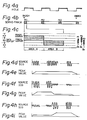
- the servo position detection mechanism l2 generates the hole signals at the position information storing portions in response to the rotation of the spindle motor ll, as shown in Fig. 4a. Since there are three position information storing portions, at least one hole signal can be obtained even if a defects occur at two of the position information storing portions.
- Each position information storing portion includes an area A and another area B, wherein position information is stored as shown by shaded lines in Fig. 4c.
- an output from the magnetic head 2e through an amplifier is represented by a waveform as shown in Fig. 4d, and corresponding outputs of peaks are shown in Fig. 4e.
- the peak held outputs at the zones A and B are identical.
- an offset or a track offset which is the difference between the peak held outputs at the zones A and B, is zero.
- the output of the magnetic head 2e is represented by a waveform as shown in Fig. 4f.
- An amplitude of the waveform where the magnetic head 2e passes the area A is large, because the magnetic head 2e faces a large shaded portion in Fig. 4c.
- An amplitude of waveform where the magnetic head 2e passes the area B is small.
- the peak values are shown in Fig. 4g. Accordingly, a positive offset (a peak value at the area A) - (a peak value at the area B) is obtained.
- a waveform of the output of the magnetic head 2e and peak values thereof are as shown in Figs. 4h and 4i, and a negative offset is obtained.
- an absolute value of the offset increases due to the amount of the displacement of the magnetic head 2e with respect to data center on the center track 50, shown in Fig. 4c. In the adjustment, a center of the magnetic head 2e is positioned at the data center.
- the offset calculation is performed when the hole signals as shown in Fig. 4a are generated.
- the encoder 3b generates a position signal S POS consisting of two phase sine waveforms, one of which has a phase lead of, for example, 90°, to the other, to discriminate the direction, in response to a motion of the magnetic head unit 2 by the voice coil motor 3a.
- a comparator l3 receives the position output from the servo position detection mechanism l2, changes the position output to a pulse signal, and outputs the signal as the hole signal S HOLE .
- the main control unit 5 includes a step pulse counter 50 which receives a step pulse signal having pulses corresponding to a logical address, as a "SEEK" command, from a disc controller in the host computer, and counts the received pulses.
- the main control unit 5 also includes an input register 5l having an identification (ID) latch 5la, a zero velocity (speed) (VO) latch 5lb, and a hole latch (HOLE) 5lc.
- the main control unit 5 further includes a microprocessor unit (MPU) 52 described below in detail, an address decoder 53 and a read-only-memory (ROM) 54.
- MPU microprocessor unit
- ROM read-only-memory
- the address decoder 53 decodes an address on an address bus A-BUS and from the MPU 52, and generates enable signals for the input register 5l and other registers in the main control unit 5, a digital-to-analog converter (DAC) 58a, and an analog-to-digital converter (ADC) 58b, and load signals for the step pulse counter 50, a difference counter 57, and timers 55a and 55b.
- the ROM 54 stores programs executed at the MPU 52.
- the ROM 54 also stores a variety of parameters, such as physical track addresses of the servo tracks.
- the main control unit 4 includes the timers 55a and 55b.
- the first timer 55a is preset to a predetermined time value from the MPU 52 through a data bus D-BUS and counts down the predetermined time value at every clock signal. When the preset time value reaches zero, the timer 55a generates an interruption signal S INT to an interruption input terminal INT of the MPU 52, requesting an interruption processing from the MPU 52.
- the main control unit 5 includes a random access memory (RAM) 56.
- the RAM 56 contains a target cylinder register for a physical track address (TCRP) 56a, a target cylinder register for a logical track address (TCRL) 56b, a present (current) cylinder register for a physical track address (PCRP) 56c, and a present cylinder register for a logical track address (PCRL) 56d.
- the RAM 56 further contains a correction confirmation flag table 56f storing flags for confirming the validity of the offset correction values C l to C n .
- the main control unit 5 includes the difference counter 57, the DAC 58a, the ADC 58b, and an output register 59.
- the difference counter 57 loads a moving track number which is the difference between a target physical track address and a current (present) physical rack address, and subtracts track cross pulses, indicating a motion of the magnetic head unit 2 by the voice coil motor 3a, from a track clock pulse generator 63.
- the DAC 58a receives the offset correction value from the MPU 52 and converts that value same to an analog value.
- the ADC 58b converts an analog peak hold signal of a servo track read signal from a peak holder 70 to a digital value and supplies the signal to the MPU 52.
- the output register 59 includes a direction (DIR) latch 59a, a seek (SEEK) latch 59b, a read inhibit (RD) latch 59c, a track zero (TRO) latch 59d, and a seek completion (SC) latch 59e.
- DIR direction
- SEEK seek
- RD read inhibit
- TRO track zero
- SC seek completion
- the DIR latch 59a holds the direction of a motion of the magnetic head unit 2 in a radial direction of the magnetic disc l; the SEEK latch 59b holds the status where the seek operation is executed; the RD latch 59c is set when the output from the read unit 7 of the read data sensed at the magnetic head 2e is inhibited and prohibits the output from the read unit 7; the TRO latch 59d is set to indicate a condition where the magnetic head 2e lies at a track address "0" to the host computer; and the SC latch 59e indicates a condition where the seek operation is completed.
- the A-BUS transmits the address from the MPU 52 to the address decoder 53 and the ROM 54.
- the D-BUS transmits data thereon between the circuit elements in the main control unit 4.
- the drive unit 6 comprises a reference speed generator 60, a speed error detector 6l, and a speed signal generator 62.
- the speed signal generator 62 receives and differentiates the position signal S POS from the encoder 3b, generating an actual speed Va of the voice coil motor 3a.
- the reference speed generator 60 generates a speed reference Vr on the basis of the output from the difference counter 57 and having a polarity defined by the direction of the DIR latch 59a.
- the speed error detector 6l receives the reference speed Vr and the actual speed Va and outputs a speed error ⁇ V : Vr - Va.
- the drive unit 6 comprises the track cross pulse generator 63, a speed zero (VO) detector 64, an adder 65, a multiplexer 66, and a voice coil motor (VCM) driver 67.
- the track pulse generator 63 receives the position signal S POS from the encoder 3b and generates the track cross pulses.
- the track cross pulses are generated at every predetermined position change of the position signal S POS , indicating the crossing of each track by the magnetic head 2e.
- the track cross pulses are supplied to the difference counter 57 which counts down the track number supplied thereto.
- the speed zero (VO) detector 64 detects the time when the actual speed Va from the speed signal generator 62 becomes approximately zero, and outputs the speed zero signal S VO to the VO latch 5lb in the input register 5l.
- the adder 65 adds the offset correction value from the DAC 58a and the position signal S POS from the encoder 3b, and outputs an offset corrected position control signal S PC .
- the multiplexer 66 receives the speed error ⁇ V and the offset corrected position control signal S PC , and outputs one of those values in response to the output from the SEEK latch 59b in the output register 59. More specifically, when the SEEK latch 59b is set the multiplexer 66 outputs the speed error ⁇ V, in other cases it outputs the position control signal S PC .
- the VCM driver 67 includes a drive transistor and drives the voice coil motor 3a in response to the output from the multiplexer 66.
- the read unit 7 comprises the peak holder 70, a data pulse generator 7l, a pseudo-data generator 72, and a multiplexer 73.
- the peak holder 70 holds a peak of the read output from the magnetic head 2e and outputs that value to the ADC 58b. This value may be used for detecting the offset.
- the date pulse generator 7l receives the read output from the magnetic head 2e and generates data pulses.
- the pseudo-data generator 72 generates a pseudo-data described later in detail.
- the multiplexer 73 receives the data pulses from the data pulse generator 7l and the pseudo-data from the pseudo-data generator 72 and outputs one thereof in response to the content set in the RD latch 59c in the output register 59. Specifically, when the RD latch 59 is set, the pseudo-data is output to the host computer, in other cases the data pulses are output.
- the main control unit 5 executes an initial operation described later with reference to Figs. 6a and 6b when the power is turned ON, calculating the offset correction values for the track zones of the magnetic disc. Subsequently, the main control unit 5 permits the reception of a command.
- the main control unit 5 receives a seek command consisting of the step pulse and the direction, from the host computer, and executes the access operation described later.
- the main control unit 5 then outputs a track zero signal S TRO from the TRO latch 59d and a seek completion signal S SC from the seek completion latch 59e to the host computer.
- the main control unit 5 gives the amount of movement of the magnetic head 2e obtained from the difference counter 57, and the offset correction value from the DAC 58a, to the drive unit 6.
- the main control unit 5 receives the VO signal S VO from the drive unit 6 and the peak hold signal from the read unit 7.
- the encoder 3b, the track cross pulse generator 63, and the difference counter 57 form a position control loop (system). Also, the encoder 3b, the speed signal generator 62 and the speed error detector 6l form a speed control loop (system). These control loops perform the position control of the voice coil motor 3a to a target track. After the speed of the voice coil motor 3a becomes approximately zero, these control loops perform a position correction control containing the offset correction by using the position signal S POS from the adder 65.
- the read unit 7 gives the peak hold signal for using the offset calculation to the main control unit 5.
- the read unit 7 also gives one of the data pulses and the pseudo-data as the read data to the host computer.
- the MPU 52 When a power is supplied to the MPS (S00l), the MPU 52 performs the seek-control for the magnetic head unit 2 at a track "0" (S002).
- An outer-guard-hand is provided at an outer circumference of the track "0" of the magnetic disc, and the magnetic head 2e is moved to the outer-guard-band by the voice coil motor 3a in response to the output from the difference counter 57.
- the magnetic head 2f reaches the outer-guard-band, the magnetic head unit 2 is stopped. Thereafter, the magnetic head 2e is moved inward of the magnetic disc in a radial direction and is positioned at the track "0" by the voice coil motor 3a.
- the MPU 52 sets zero to the PCRP 56c and the PCRL 56d as a current address, i.e., the track "0".
- the MPU 52 reads a servo track address in the zone l, i.e., the physical address "50", from the ROM 54 and sets the physical address "50" to the TCRP 56a as the target track address (S004).
- the MPU 52 also sets a servo-correction flag to the correction confirmation flag table 56f (S005).
- the MPU 52 executes the seek control to position the magnetic head 2e at the target track, i.e., the servo track.
- the seek control can be carried out by the sequences (steps 02l to 03l) shown in Fig. 7 and explained below.
- the MPU 52 calculates the difference between the target physical address stored in the TCRP 56a and the present (current) physical address stored in the PCRP 56C and sets the calculated difference to the difference counter 57 as the moving distance.
- the MPU 52 sets the direction of which value is "l" when the target physical address is greater than the current physical address, or in other cases sets the value zero, to the DIR latch 59a (S02l).
- the MPU 52 sets "l” to the SEEK latch 59b (S022).
- the multiplexer 66 is made to select the speed error ⁇ V from the speed error detector 6l.
- the reference speed generator 60 generates the reference speed Vr in response to the output of the difference counter 57.
- the reference speed Vr has a polarity decided by the content of the DIR latch 59a.
- the encoder 3b outputs the position signal S POS in response to a motion of the voice coil motor 3a, and the track cross pulse generator 63 outputs track cross pulses, subtracting the count in the difference counter 57. In this way, the position control and the speed control are carried out, and the magnetic head 2e is moved to the target physical track address by the voice coil motor 3a.
- Steps 023 and 024 (S023 and S024)
- the MPU 52 reads and checks the count in the difference counter 57 (S023, S024). When the count is zero, it is deemed that the magnetic head 2e has reached the target physical track address.
- Steps 025 and 026 (S025 and S026)
- the MPU 52 reads the content in the VO latch 5lb (S025).
- the VO detector 64 generates the zero speed signal when the actual speed Va falls to approximately zero, and the zero speed signal is latched in the VO latch 5lb at a logical "one". Accordingly, the MPU 52 checks the VO latched content (S026), and determines whether or not the speed of the voice coil motor 3a is zero when the VO latched content is one.
- the MPU 52 starts the position control.
- the MPU 52 clears the SEEK latch 59b in the output register 59. As a result, the multiplexer 66 is made to output the position signal S PC from the adder 65.
- Steps 028 to 030 (S028 to S030)
- the MPU 52 checks a corresponding servo correction flag in he correction confirmation flag table 56f (S028). When the corresponding flag is indicates an offset measurement, the MPU 52 sets zero to the DAC 58a (S029). Otherwise, the MPU 52 reads the offset correction value of the zone of the target physical track address in the TCRP 56a from the offset correction register 56e and sets that value to the DAC 58a (S030), thus carrying out the normal access operation with the offset correction. As a result, the adder 65 adds the offset correction value from the DAC 58a and the position signal S POS from the encoder 3b. The offset-corrected position signal S PC is supplied to the voice coil motor driver 67 through the multiplexer 66. The voice coil motor 3a can be fine-controlled.
- the MPU 52 waits for a predetermined time, and then completes the seek control.
- step 007 S007 in Fig. 6a.
- the MPU 52 effects the offset measurement.
- the offset measurement can be carried out by the sequence shown in Fig. 8, as explained below.
- Steps 04l and 042 (S04l and S042)
- the MPU 52 resets the HOLE latch 5la in the input register 5l (S04l).
- the hole signal is generated at the comparator l3 in response to the rotation of the spindle motor ll at every position corresponding to the servo information storing portion on the magnetic disc lc.
- the MPU 52 then checks the HOLE latch after a reset (S042).
- Steps 043 to 045 (S043 to S045)
- the magnetic head 2e When the HOLE latch 5lc is set, the magnetic head 2e has read the position information on the servo track.
- Steps 046 and 047 (S046 and S047)
- the MPU 52 stores the OFFSET to a corresponding area in the offset correction register 56e, and sets a flag to a corresponding area in the correction confirmation flag table 56f. Thereafter, the MPU 52 transfers the control to step 008 (S008) in Fig. 6b.
- the MPU 52 sets the target physical track address in the TCRP 56a to the PCRP 56c as the present physical track address.
- the servo track information read for a single servo track is obtained.
- the MPU 52 checks whether or not the servo track information read for all servo tracks is completed (S009).
- the MPU 52 reads a next servo track address from the ROM 54 and sets the address to the TCRP 56a. The control is then transferred to step 006 and a next servo track information read is carried out.
- the MPU 52 When the servo track information read for all servo tracks is completed, the MPU 52 resets the corresponding servo correction flag in the correction confirmation flag table 56f (S0ll), and sets zero as the physical track address to the TCRP 56a (S0l2).
- the MPU 52 carries out the seek control as shown in Fig. 7 in the same manner set forth above (S0l3), and as a result, the magnetic head 2f can be positioned at the track "0".
- the MPU 52 sets zero as the present track address to the PCRP 56c and PCRL 56d (S0l4), and then sets a time for updating the offset correction to the timer 55a, and starts the timer 55a (S0l5).
- the MPU 52 sets a logical "l" to the TRO latch 59d and the SC latch 59e in the output register 59.
- the track zero signal S TRO in the TRO latch 59d and the seek complete signal S SC in the SC latch 59e are transmitted to the host computer.
- Steps 05l to 056 (S05l to S056)
- the MPU 52 reads the count in the step pulse counter 50 (S05l), and checks whether or not the count is zero (S052).
- the host computer gives the step pulses corresponding to a relative logical track address as a seek command, and a count of zero in the step pulse counter 50 indicates that the seek command has not reached the main control unit 5.
- the MPU 52 waits. Otherwise, the MPU 52 transfers the count in the step pulse counter 50 to the TCRL 56b for storing the target logical track address (S053).
- the MPU 52 waits for a predetermined time (S054), and then again reads the count in the step pulse counter 50 (S055) and compares this count with the target logical track address in the TCRL 56b (S56). If the count does not coincide with the target logical track address, the transfer of the seek command from the host computer continues.
- the MPU 52 then repeats the operations of steps 053 to 056.
- Steps 057 and 058 (S057 and S058)
- the seek command transfer is completed, and the MPU 52 reads the direction from the host computer and stored in the ID latch 5la (S057).
- the MPU 52 then calculates a target logical track address on the basis of the logical relative track address in the TCRL 56b and the present logical track address in the PCRL 56d, and sets that address to the TCRL 56b (S058).
- the MPU 52 translates the calculated target logical track address to a target physical track address, by a translation method as shown in Fig. l0.
- the translation in Fig. l0 is based on the relationship of the physical track address including the servo track addresses and the logical track address, as shown in Fig. 3.
- the MPU 52 saves the translated target physical track address to the TCRP 56a.
- the MPU 52 finds a track zone corresponding to the target physical track address in the TCRP 56a, and confirms a flag in the correction confirmation flag table 56f corresponding to the found track zone (S060).
- the flags are reset to update the offset correction values.
- the flags are reset, and accordingly, the offset correction values are invalid. The above confirmation can be carried out to check the validity of the offset correction values.
- step 063 When a corresponding flag is set, the MPU 52 continues to step 063, or in other cases, to step 062.
- the offset measurement is carried out as shown in Fig. ll.
- Steps 08l to 083 (S08l to S083)
- the MPU 52 sets the corresponding servo correction flag to the correction confirmation flag table 56f (S08l). Second, the MPU 52 transfers the target physical track address from the TCRP 56a to the PCRL 56d (S082). Then, the MPU 52 reads a servo track address in the track zone of the target physical track address from the ROM 54 and transfer that address to the TCRP 56a (S083).
- the seek control is effected by the sequences as shown in Fig. 7, and as a result, the magnetic head 2f is positioned at the above desired servo track.
- the offset correction is carried out by the sequences as shown in Fig. 8, and as a result, the offset correction value of that track zone can be obtained and stored in a corresponding area of the offset correction register 56e.
- the corresponding flag in the correction confirmation flag table 56f is also set.
- the MPU 52 resets the servo correction flag (S086), and transfers the target servo track address in the TCRP 56a to the PCRP 56c as the present physical track address (S087).
- the MPU 52 then restores the target physical track address saved in the PCRL 56d to the TCRP 56a (S088), and finally, the MPU 52 resets the VO latch 5lb (S089).
- step 063 S063 in Fig. 9b.
- the seek control is carried out in accordance with the sequence of Fig. 7.
- the seek control is achieved on the basis of the target physical track address in the TCRP 56a and the present physical track address in the PCRP 56c and as a result, the magnetic head 2e is positioned at a data track of the target physical track address.
- the MPU 52 transfers the target physical track address in the TCRP 56a to the PCRP 56c as the present physical track address and transfers the target logical track address in the TCRL 56b to the PCRL 56d as the present logical track address.
- the MPU 52 clears the step pulse counter 50 and the VO latch 5lb (S065), and checks the present logical track address in the PCRL 56d (S066). When the present logical track address is zero, in other words, when the magnetic head 2f is positioned at the track "0", the MPU 52 sets the TRO latch 59d (S067), or in other cases, resets the TRO latch 59d (S068).
- the MPU 52 resets the RD latch 59c to change the selection mode at the multiplexer 73 for outputting the data from the data pulse generator 7l (S069), and at the same time, sets the SC latch 59e to output the seek completion signal S SC to the host computer.
- the operation is then transferred step 05l and the above access processing is repeated.
- the host computer reads the data pulses from the data pulse generator 7l through the multiplexer 73 as read data and confirms the track number contained in the read data from the main control unit 5. If it is a read command, the host computer reads subsequent read data from the data pulse generator 7l. On the other hand, if it is a write command, the host computer writes data on the track through a write unit (not shown).
- the host computer gives the logical track address to the main controller 5 and the access with the offset correction for the physical track address for not only the magnetic discs provided with all data tracks but also the magnetic disc lc provided with servo tracks and data tracks is realized.
- the offset measurement is carried out at the initial operation, and in addition, is carried out at the reception of the seek command.
- offset measurement should be carried out. However, if the offset measurement is carried out at each reception of the seek command, each seek time may become too long. Accordingly, the offset measurement should be carried out at a suitable time. On the other hand, in the above operation, if the offset measurement is carried out for the track zone where the seek command is generated to the track zone, and if the seek command is not generated for the track zones, the offset measurement for the track zones is not carried out. Under this condition, when the write access is carried out to the track zone in response to the seek access generation therefor, non-updated offset values can be used, and as a result, a data destroy due to position displacement may occur.
- the compulsorily interruption processing for achieving the offset measurement must be carried out in good time.
- the offset measurement can be carried out while keeping a fundamental relationship between the host computer and the magnetic disc system.
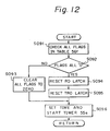
- the MPU 52 starts the timer 55a with a predetermined time, and the timer 55a counts down the time by a timing pulse. When the time becomes zero, the timer 55a generates the interruption signal S INT and starts the offset measurement in the MPU 52. This operation will be described in more detail with reference to Fig. l2.
- Steps 09l, 092, 093 and 096 (S09l, S092, S093 and S096)
- the MPU 52 Upon receipt of the interruption signal S INT , the MPU 52 checks all flags in the correction confirmation flag table 56f (S09l). If all flags are not zero, the MPU 52 clears the flags to zero, compulsorily setting the flags in an invalid condition (S092), loads the time to and starts the timer 55a (S096).
- Steps 092, 094, 095 and 096 S092, S094, S095 and S096)
- the MPU 52 sets the RD latch 59c to inhibit the output of the data from the data pulse generator 7l through the multiplexer 72; in other words, to output the pseudo-data from the pseudo-data generator 72 (S094).
- the MPU 52 resets the TRO latch 59d to output the track "0" signal STRO of logical "0" to the host computer (S095), and the MPU 52 then execute the processing of step 096.
- the host computer may consider that the seek operation is incomplete and then retry the seek command transmission. Accordingly, by this virtual malfunction, the fundamental relationship between the host computer and the magnetic disc system is maintained. In other words, the host computer does not require an additional processing, and a data neglect for writing or reading is avoided.
- the above pseudo-data output can be replaced to cut data output instead of the pseudo-data output, for example, all one or all zero. This can be easily achieved by removing the pseudo-data generator 72.
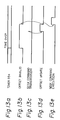
- Fig. l4a at a power ON (PWR ON), the offset measurement of the initial operation is carried out, and the measured offset values for all track zones are stored in the offset correction register 56e. All flags in the correction confirmation flag table 56f are also set, and thereafter, the timer 55a is initiated with the time T1. Before a lapse of the first time T1 , all offset values for the track zones l to 4, obtained at the initial offset measurement, are valid (Figs. l4c to l4f). During the first time T1 , the access is executed with the offset value for a seek command to each track zone.
- the interruption signal S INT is generated, and all offset values for all track zones are made invalid.
- the timer 55a is again set to the time T1.
- the offset measurement for the track zone relevant to the seek command in the example, the track zone l
- the update of the measured offset value to a corresponding area in the offset correction register 56e, and the setting of a corresponding flag in the correction confirmation flag table 56f are carried out.
- the access is carried out by using an updated offset value. Note that the offset measurement for other track zones is not performed so that an access time for the seek command transmission is maintained as a short time.
- the offset measurement for another track zone can be carried out.
- the offset measurement is not carried out for the time T n-1 . If the seek command is generated for a next time T n , the offset measurement is effected. However, if a read or write command without a seek command is generated, in other word, a read or write command to a same track address is generated, the access of the magnetic head is not effected and only the read or write operation is effected. In this case, the offset measurement is not carried out. However, a new displacement of the track address may be generated. Under this condition, a correct read or write operation is not guaranteed.
- the RD latch 59c is set at step 094.
- the host computer then reads the pseudo data but cannot discriminate the track number, and consequently, the host computer decides that an error has occurred.
- the retry operation is the seek operation for the track "0", and as a result, the seek operation of step 002 in Fig. 6a is carried out.
- the host computer sends a seek command to the above read or write track, the offset update of the track zone is carried out, and the access is performed by using the updated offset value.
- the RD latch 59c is reset to output the data from the data pulse generator 7l.
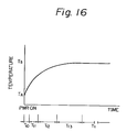
- the magnetic discs and the mechanism therefor are in a cold state where the temperature is low, for example, an ambient temperature T A , in an initial condition at the power ON.
- the temperature may be greatly increased with time, as shown in Fig. l6, and the temperature may saturate at a constant temperature T S .
- the offset may be greatly changed, and accordingly, a more precise offset update is needed during this interval.
- the second timer 55b in the main control unit 5 in Fig. 5 is provided to generate the interruption signal S INT to the MPU 52 during the above time, and the times T10 , T11 , T12 and T13 , as shown in Fig. l6, are determined on the basis of the temperature change.
- One of these times is set to the timer 55b by the MPU 52 with a time lapse, and the above offset update is carried out in response to each time lapse.
- the operation of the timer 55b is similar to that of the timer 55a, and thus a description thereof is omitted.
- the timer 55a may be used instead of the timer 55a, and the above interruption operation may be carried out.
- the above interruption using the timer 55b for the temperature change time can be easily replaced on the basis of a constant temperature change.
- the transient interruption operation may be terminated.
- the logical track address from the host computer is the step pulse as a relative quantity and the step pulse counter 50 is used.
- the logical track address can be replaced by absolute type data, for example, serial data in digital form.
Landscapes
- Moving Of The Head To Find And Align With The Track (AREA)
- Moving Of Head For Track Selection And Changing (AREA)
Description
- The present invention relates to a magnetic disc system. More particularly, it relates to a track access control system for a magnetic disc system which uses an offset obtained from servo-tracks provided in a magnetic disc, in addition to data tracks, as a correction value of a track access, and enables a host computer to access data on physical tracks in the magnetic disc by using logical tracks.
- Recently, in rotation type magnetic disc systems, a distance between tracks on a magnetic disc has become short due to requirements for a high density and a large capacity of data storage. In those magnetic disc systems, the displacement of the tracks, i.e., an offset, caused by an error in magnetic head installation, temperature changes, etc., cannot be neglected, and a correction of this displacement is necessary for data access.
- Accordingly, magnetic disc systems in which servo tracks storing servo positioning information are provided are known. In those magnetic systems, the magnetic head is positioned at the servo track to read the servo positioning information, a displacement of the servo track is detected, and the detected displacement is used as an offset value for correcting the displacement and positioning the magnetic head at the subsequent head accessing when access to a data track is required.
- In a magnetic disc system, two types of track address, i.e., a physical track address and a logical track address, are defined. The physical track address designates actual tracks comprised by data tracks and servo tracks on the magnetic disc, but the logical track address designates only data tracks. A plurality of magnetic discs may be provided in the magnetic disc system, but in order to save effort storing servo information into all magnetic discs, the servo tracks may be partially formed on at least one face of a magnetic disc. Accordingly, the face of the magnetic disc in question is provided with the servo tracks and the data tracks. In this system, the physical track addresses designating the servo track addresses and the data track addresses differ from the logical track addresses. Another face of the magnetic disc and the other magnetic discs are provided with only data tracks.
- In this case, the physical track addresses coincide with the logical track addresses.
- As described above, handling of the track address is relatively difficult, and when the handling is to be processed by a host computer, the programming of the host computer is complex (JPP49-117007).
- Another prior art magnetic disc system disclosed in USP 4,396,959 also suffers from the following disadvantages:
- a) since two or more servo sectors cannot be provided in each track, i.e., only one servo sector is provided in each track, if a defect occurs in the servo sector, the offset measurement therefor cannot be effected, and
- b) due to the provision of the servo sector in each track a rotation speed of the disc must be reduced, and, the density of the memory storage in a circumferential direction must be increased.
- Accordingly, it is desirable to provide an improved track access control system for a magnetic disc system with an offset correction.
- DE-A-2 730 394 discloses a track access control system for a magnetic disc system according to the preamble of accompanying
claim 1. Offset measurement is carried out by moving the head to reference tracks on the disc, a positional error being measured at a number of positions as the disc rotates. The offset measurement test is carried out periodically and adaptively dependent on the rate of change of temperature. - According to the present invention, there is provided a track access control system for a magnetic disc system connected to a host computer issuing a seek command, said track access control system comprising:-
a magnetic disc unit including at least one magnetic disc, at least one face of which includes a plurality of servo tracks having one or more servo information storing portions and a plurality of data tracks in a radial direction thereof, the servo tracks being located among the data tracks;
at least one magnetic head for accessing said tracks on said face of said magnetic disc;
magnetic head moving means, connected to said magnetic head, for moving said magnetic head in the radial direction;
control means for controlling said magnetic head via said magnetic head moving means, to position said magnetic head at a desired radial position on said magnetic disc;
rotation means, connected to said magnetic disc unit, for rotating said magnetic disc unit;
timing signal generation means, connected to said rotation means, for generating a timing signal corresponding to a rotation of said servo information storing portions;
servo data generation means, connected to said magnetic head for reading servo information from said servo information storing portions through said magnetic head, and generating servo data in response to said timing signal of said timing signal generation means;
track offset update means, connected to said servo data generation means, for measuring and updating a track offset from said servo data for said plurality of servo tracks;
characterised in that each servo track has a plurality of separate servo information storing portions along the circumference of a circle; and in that said track access control system further comprises:-
track address translation means for receiving a target logical track address by said seek command, from said host computer, which is a track address sequentially given to only said plurality of data tracks in a radial direction, and for translating said target logical track address into a target physical track address, which is another track address sequentially given to said plurality of data tracks and said plurality of servo tracks in a radial direction, based upon the track structure of the magnetic disc to be accessed, wherein when said servo tracks are located between a track of a current logical track address and a track of a target logical track address, a number of the servo tracks located therebetween are added to said target logical track address in order to translate said logical track address into said physical track address; and wherein
said control means is connected to said track offset update means and said track address translation means, for controlling said magnetic head through said magnetic head moving means by using said measured track offset corresponding to a translated target physical track to be moved thereat, to position said magnetic head at said translated physical track. - The plurality of servo tracks may be provided in each of the track zones equally divided into physical tracks in the radial direction. Each servo track in each track zone may be provided at approximately the centre of each zone.
- The track offset update unit may update all track offsets for all track zones in an initial condition. The track offset update unit may update a track offset which is not updated in a predetermined time. Also, the track offset update unit may update a track offset in response to the reception of a seek command for moving the magnetic disc to a different track zone when the different track zone is not offset-update offset unit predetermined time. In addition, the updated in the may be compulsorily energized when at least one track zone is not offset-updated in the predetermined time. The control unit may output an error date for an access command when the track offset update unit is compulsorily energized, and the control unit may output normal data when the track offset update unit terminates the offset update.
- The track offset update unit may be compulsorily energized in response to a predetermined temperature change of at least the magnetic disc during the temperature transient state. The track offset update unit may be also compulsorily energized in another predetermined time defined by a constant temperature change for the temperature transient state.
- Reference will now be made, by way of example, to the accompanying drawings, in which:
- Fig. l is a diagram of an embodiment of a magnetic disc system according to the present invention;
- Fig. 2 is a plan view of a magnetic disc in Fig. l provided with servo tracks in addition to data tracks;
- Fig. 3 is a view representing the relationship of the servo tracks and the data tracks on the magnetic disc in Fig. 2;
- Figs. 4a to 4i are graphs representing servo information and an offset value of the magnetic disc in Figs. 2 and 3;
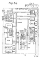
- Fig. 5 is a circuit diagram of the magnetic disc system in Fig. l;
- Figs. 6a and 6b are flow charts of an initial operation of the magnetic disc system in Fig. 5;
- Fig. 7 is a flow chart of the seek operation of the magnetic disc system in Fig. 5;
- Fig. 8 is a flow chart of the offset measurement of the magnetic disc system in Fig. 5;
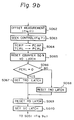
- Figs. 9a and 9b are flow charts of the access operation of the magnetic disc system in Fig. 5;
- Fig. l0 is a flow chart of a track address translation form a logical track address to a physical track address of the magnetic disc system in Fig. 5;
- Fig. ll is a flow chart of the offset measurement;
- Fig. l2 is a flow chart explaining an interruption for energizing the offset update operation;
- Figs. l3a to l3e, l4a to l4f and l5a to l5h are timing chart illustrating the interruption and the offset measurement operation; and
- Fig. l6 is a graph illustrating the temperature change of the magnetic disc with time.
- A magnetic disc system in Fig. l includes a magnetic disc unit l consisting of a plurality of magnetic discs la to ld each mounted on a rotary shaft l0, a
magnetic head unit 2 consisting of a plurality ofmagnetic heads 2a to 2h, a movingunit 3 consisting of avoice coil motor 3a and anencoder 3b, a spindle motor ll mechanically connected to and rotating the rotary shaft l0, and a servo position detection mechanism l2. The magnetic disc system further includes a control means 4 having amain control unit 5, adrive unit 6, and aread unit 7. A host computer is connected to themain control unit 5. - Each magnetic disc is coated with a magnetic recording medium on both faces thereof. As shown in Fig. 2, an upper face of the magnetic disc lc, which is positioned at approximately middle of the magnetic discs in a vertical direction, is provided with servo tracks SVT and data tracks which are defined as other tracks of the servo tracks SVT, along a radial direction. A lower face of the magnetic disc lc and both faces of the magnetic discs la, lb, and ld are provided with data tracks, but are not provided with servo tracks. Figure 3 is a conceptual view of the upper face of the magnetic disc lc. On the upper face, 400 physical addresses are defined, corresponding to 400 actual tracks including servo tracks 49, 50, 5l; l49, l50, l5l; 249, 250, 25l; and 349, 350 and 35l. on the other hand, 388 logical addresses which do not include the servo tracks are also defined. Tracks of
physical addresses 0 to 48, 52 to l48, l52 to 248, 252 to 348 and 352 to 400 are data tracks. In this embodiment, l00 actual tracks form one zone, and at a middle portion of each zone, a servo track SVT consisting of three tracks is provided. - The other magnetic discs are provided with only data tracks, but the data tracks corresponding to the servo tracks cannot be used as data tracks.
- The servo position detection mechanism l2 directly connected to the spindle motor ll generates a "HOLE" signal corresponding to a position storing position information of the servo track SVT. The
magnetic heads 2a to 2h read from or write to the magnetic discs la to ld, and thevoice coil motor 3a supports themagnetic heads 2a to 2h through plate-springs and moves theheads 2a to 2h in a radial direction of the magnetic discs to enable these heads to access a desired track. - As shown in Figs. 2 and 4, each servo track, for example, the servo tracks 49, 50, and 5l includes three portions storing position information PIl to PI3 along the track thereof at a predetermined angle, in this example l20°C, in a circle. Reference "INDEX" denotes an origin of the rotation of the magnetic disc. The servo position detection mechanism l2 generates the hole signals at the position information storing portions in response to the rotation of the spindle motor ll, as shown in Fig. 4a. Since there are three position information storing portions, at least one hole signal can be obtained even if a defects occur at two of the position information storing portions.
- Each position information storing portion includes an area A and another area B, wherein position information is stored as shown by shaded lines in Fig. 4c. When the
magnetic head 2e is positioned at a portion Pl denoting the center of the servo track SVT, an output from themagnetic head 2e through an amplifier is represented by a waveform as shown in Fig. 4d, and corresponding outputs of peaks are shown in Fig. 4e. The peak held outputs at the zones A and B are identical. As a result, an offset or a track offset, which is the difference between the peak held outputs at the zones A and B, is zero. When themagnetic head 2e is positioned at a portion P2 slightly shifted toward thetrack 49, as shown in Fig. 4c, the output of themagnetic head 2e is represented by a waveform as shown in Fig. 4f. An amplitude of the waveform where themagnetic head 2e passes the area A is large, because themagnetic head 2e faces a large shaded portion in Fig. 4c. An amplitude of waveform where themagnetic head 2e passes the area B is small. The peak values are shown in Fig. 4g. Accordingly, a positive offset (a peak value at the area A) - (a peak value at the area B) is obtained. On the other hand, when themagnetic head 2e is positioned at a portion P3, a waveform of the output of themagnetic head 2e and peak values thereof are as shown in Figs. 4h and 4i, and a negative offset is obtained. Note, an absolute value of the offset increases due to the amount of the displacement of themagnetic head 2e with respect to data center on thecenter track 50, shown in Fig. 4c. In the adjustment, a center of themagnetic head 2e is positioned at the data center. - The offset calculation is performed when the hole signals as shown in Fig. 4a are generated.
- A specific circuit construction of the
main control unit 5, thedrive unit 6, and theread unit 7 will be described with reference to Fig. 5. - In Fig. 5, the
encoder 3b generates a position signal SPOS consisting of two phase sine waveforms, one of which has a phase lead of, for example, 90°, to the other, to discriminate the direction, in response to a motion of themagnetic head unit 2 by thevoice coil motor 3a. A comparator l3 receives the position output from the servo position detection mechanism l2, changes the position output to a pulse signal, and outputs the signal as the hole signal SHOLE. - The
main control unit 5 includes astep pulse counter 50 which receives a step pulse signal having pulses corresponding to a logical address, as a "SEEK" command, from a disc controller in the host computer, and counts the received pulses. Themain control unit 5 also includes an input register 5l having an identification (ID) latch 5la, a zero velocity (speed) (VO) latch 5lb, and a hole latch (HOLE) 5lc. the ID latch 5la receives and holds a direction signal DIR from the disc controller; the VO latch 5lb receives and holds a zero speed signal SVO from a zerospeed detector 64 in thedrive unit 6 indicating that a speed of thevoice coil motor 3a is zero; and the HOLE latch 5lc receives and holds the hole signal SHOL from the comparator l3. Themain control unit 5 further includes a microprocessor unit (MPU) 52 described below in detail, anaddress decoder 53 and a read-only-memory (ROM) 54. Theaddress decoder 53 decodes an address on an address bus A-BUS and from theMPU 52, and generates enable signals for the input register 5l and other registers in themain control unit 5, a digital-to-analog converter (DAC) 58a, and an analog-to-digital converter (ADC) 58b, and load signals for thestep pulse counter 50, adifference counter 57, andtimers ROM 54 stores programs executed at theMPU 52. TheROM 54 also stores a variety of parameters, such as physical track addresses of the servo tracks. Themain control unit 4 includes thetimers first timer 55a is preset to a predetermined time value from theMPU 52 through a data bus D-BUS and counts down the predetermined time value at every clock signal. When the preset time value reaches zero, thetimer 55a generates an interruption signal SINT to an interruption input terminal INT of theMPU 52, requesting an interruption processing from theMPU 52. - The
main control unit 5 includes a random access memory (RAM) 56. TheRAM 56 contains a target cylinder register for a physical track address (TCRP) 56a, a target cylinder register for a logical track address (TCRL) 56b, a present (current) cylinder register for a physical track address (PCRP) 56c, and a present cylinder register for a logical track address (PCRL) 56d. TheRAM 56 also contains an offsetcorrection register 56e storing offset correction values Cl to Cn for track zones. As shown in Fig. 3, in this embodiment the number of zones is four: n = 4. TheRAM 56 further contains a correction confirmation flag table 56f storing flags for confirming the validity of the offset correction values Cl to Cn. - The
main control unit 5 includes thedifference counter 57, theDAC 58a, the ADC 58b, and anoutput register 59. The difference counter 57 loads a moving track number which is the difference between a target physical track address and a current (present) physical rack address, and subtracts track cross pulses, indicating a motion of themagnetic head unit 2 by thevoice coil motor 3a, from a trackclock pulse generator 63. TheDAC 58a receives the offset correction value from theMPU 52 and converts that value same to an analog value. The ADC 58b converts an analog peak hold signal of a servo track read signal from apeak holder 70 to a digital value and supplies the signal to theMPU 52. Theoutput register 59 includes a direction (DIR)latch 59a, a seek (SEEK)latch 59b, a read inhibit (RD)latch 59c, a track zero (TRO) latch 59d, and a seek completion (SC)latch 59e. TheDIR latch 59a holds the direction of a motion of themagnetic head unit 2 in a radial direction of the magnetic disc l; the SEEKlatch 59b holds the status where the seek operation is executed; theRD latch 59c is set when the output from theread unit 7 of the read data sensed at themagnetic head 2e is inhibited and prohibits the output from theread unit 7; the TRO latch 59d is set to indicate a condition where themagnetic head 2e lies at a track address "0" to the host computer; and theSC latch 59e indicates a condition where the seek operation is completed. - The A-BUS transmits the address from the
MPU 52 to theaddress decoder 53 and theROM 54. The D-BUS transmits data thereon between the circuit elements in themain control unit 4. - The
drive unit 6 comprises areference speed generator 60, a speed error detector 6l, and aspeed signal generator 62. Thespeed signal generator 62 receives and differentiates the position signal SPOS from theencoder 3b, generating an actual speed Va of thevoice coil motor 3a. Thereference speed generator 60 generates a speed reference Vr on the basis of the output from thedifference counter 57 and having a polarity defined by the direction of theDIR latch 59a. The speed error detector 6l receives the reference speed Vr and the actual speed Va and outputs a speed error ΔV : Vr - Va. Thedrive unit 6 comprises the trackcross pulse generator 63, a speed zero (VO)detector 64, anadder 65, amultiplexer 66, and a voice coil motor (VCM)driver 67. Thetrack pulse generator 63 receives the position signal SPOS from theencoder 3b and generates the track cross pulses. The track cross pulses are generated at every predetermined position change of the position signal SPOS, indicating the crossing of each track by themagnetic head 2e. The track cross pulses are supplied to thedifference counter 57 which counts down the track number supplied thereto. The speed zero (VO)detector 64 detects the time when the actual speed Va from thespeed signal generator 62 becomes approximately zero, and outputs the speed zero signal SVO to the VO latch 5lb in the input register 5l. Theadder 65 adds the offset correction value from theDAC 58a and the position signal SPOS from theencoder 3b, and outputs an offset corrected position control signal SPC. Themultiplexer 66 receives the speed error ΔV and the offset corrected position control signal SPC, and outputs one of those values in response to the output from the SEEKlatch 59b in theoutput register 59. More specifically, when the SEEKlatch 59b is set themultiplexer 66 outputs the speed error ΔV, in other cases it outputs the position control signal SPC. TheVCM driver 67 includes a drive transistor and drives thevoice coil motor 3a in response to the output from themultiplexer 66. - The
read unit 7 comprises thepeak holder 70, a data pulse generator 7l, apseudo-data generator 72, and amultiplexer 73. Thepeak holder 70 holds a peak of the read output from themagnetic head 2e and outputs that value to the ADC 58b. This value may be used for detecting the offset. The date pulse generator 7l receives the read output from themagnetic head 2e and generates data pulses. Thepseudo-data generator 72 generates a pseudo-data described later in detail. Themultiplexer 73 receives the data pulses from the data pulse generator 7l and the pseudo-data from thepseudo-data generator 72 and outputs one thereof in response to the content set in theRD latch 59c in theoutput register 59. Specifically, when theRD latch 59 is set, the pseudo-data is output to the host computer, in other cases the data pulses are output. - To summarize the operation of the
main control unit 5, thedrive unit 6 and theread unit 7, themain control unit 5 executes an initial operation described later with reference to Figs. 6a and 6b when the power is turned ON, calculating the offset correction values for the track zones of the magnetic disc. Subsequently, themain control unit 5 permits the reception of a command. Themain control unit 5 receives a seek command consisting of the step pulse and the direction, from the host computer, and executes the access operation described later. Themain control unit 5 then outputs a track zero signal STRO from the TRO latch 59d and a seek completion signal S SC from the seekcompletion latch 59e to the host computer. Also, themain control unit 5 gives the amount of movement of themagnetic head 2e obtained from thedifference counter 57, and the offset correction value from theDAC 58a, to thedrive unit 6. Themain control unit 5 receives the VO signal SVO from thedrive unit 6 and the peak hold signal from theread unit 7. - The
encoder 3b, the trackcross pulse generator 63, and thedifference counter 57 form a position control loop (system). Also, theencoder 3b, thespeed signal generator 62 and the speed error detector 6l form a speed control loop (system). These control loops perform the position control of thevoice coil motor 3a to a target track. After the speed of thevoice coil motor 3a becomes approximately zero, these control loops perform a position correction control containing the offset correction by using the position signal SPOS from theadder 65. - The
read unit 7 gives the peak hold signal for using the offset calculation to themain control unit 5. Theread unit 7 also gives one of the data pulses and the pseudo-data as the read data to the host computer. - Referring to Figs. 6a and 6b, the initial operation (processing) will be described.
- When a power is supplied to the MPS (S00l), the
MPU 52 performs the seek-control for themagnetic head unit 2 at a track "0" (S002). An outer-guard-hand is provided at an outer circumference of the track "0" of the magnetic disc, and themagnetic head 2e is moved to the outer-guard-band by thevoice coil motor 3a in response to the output from thedifference counter 57. When themagnetic head 2f reaches the outer-guard-band, themagnetic head unit 2 is stopped. Thereafter, themagnetic head 2e is moved inward of the magnetic disc in a radial direction and is positioned at the track "0" by thevoice coil motor 3a. Subsequently, theMPU 52 sets zero to thePCRP 56c and the PCRL 56d as a current address, i.e., the track "0". - The
MPU 52 reads a servo track address in the zone l, i.e., the physical address "50", from theROM 54 and sets the physical address "50" to theTCRP 56a as the target track address (S004). TheMPU 52 also sets a servo-correction flag to the correction confirmation flag table 56f (S005). - The
MPU 52 executes the seek control to position themagnetic head 2e at the target track, i.e., the servo track. The seek control can be carried out by the sequences (steps 02l to 03l) shown in Fig. 7 and explained below. - The
MPU 52 calculates the difference between the target physical address stored in theTCRP 56a and the present (current) physical address stored in the PCRP 56C and sets the calculated difference to thedifference counter 57 as the moving distance. TheMPU 52 sets the direction of which value is "l" when the target physical address is greater than the current physical address, or in other cases sets the value zero, to theDIR latch 59a (S02l). TheMPU 52 sets "l" to the SEEKlatch 59b (S022). As a result, themultiplexer 66 is made to select the speed error ΔV from the speed error detector 6l. Thereference speed generator 60 generates the reference speed Vr in response to the output of thedifference counter 57. The reference speed Vr has a polarity decided by the content of theDIR latch 59a. The speed error detector 6l calculates the speed error ΔV = Vr - Va, and the voicecoil motor driver 67 receives the speed error ΔV through themultiplexer 66 and drives thevoice coil motor 3a. Theencoder 3b outputs the position signal SPOS in response to a motion of thevoice coil motor 3a, and the trackcross pulse generator 63 outputs track cross pulses, subtracting the count in thedifference counter 57. In this way, the position control and the speed control are carried out, and themagnetic head 2e is moved to the target physical track address by thevoice coil motor 3a. - The
MPU 52 reads and checks the count in the difference counter 57 (S023, S024). When the count is zero, it is deemed that themagnetic head 2e has reached the target physical track address. - The
MPU 52 reads the content in the VO latch 5lb (S025). TheVO detector 64 generates the zero speed signal when the actual speed Va falls to approximately zero, and the zero speed signal is latched in the VO latch 5lb at a logical "one". Accordingly, theMPU 52 checks the VO latched content (S026), and determines whether or not the speed of thevoice coil motor 3a is zero when the VO latched content is one. - Subsequently, the
MPU 52 starts the position control. - The
MPU 52 clears the SEEKlatch 59b in theoutput register 59. As a result, themultiplexer 66 is made to output the position signal SPC from theadder 65. - The
MPU 52 checks a corresponding servo correction flag in he correction confirmation flag table 56f (S028). When the corresponding flag is indicates an offset measurement, theMPU 52 sets zero to theDAC 58a (S029). Otherwise, theMPU 52 reads the offset correction value of the zone of the target physical track address in theTCRP 56a from the offsetcorrection register 56e and sets that value to theDAC 58a (S030), thus carrying out the normal access operation with the offset correction. As a result, theadder 65 adds the offset correction value from theDAC 58a and the position signal SPOS from theencoder 3b. The offset-corrected position signal SPC is supplied to the voicecoil motor driver 67 through themultiplexer 66. Thevoice coil motor 3a can be fine-controlled. - The
MPU 52 waits for a predetermined time, and then completes the seek control. - The control is restored to step 007 (S007) in Fig. 6a. At step 007, the
MPU 52 effects the offset measurement. The offset measurement can be carried out by the sequence shown in Fig. 8, as explained below. - The
MPU 52 resets the HOLE latch 5la in the input register 5l (S04l). As set forth above, the hole signal is generated at the comparator l3 in response to the rotation of the spindle motor ll at every position corresponding to the servo information storing portion on the magnetic disc lc. TheMPU 52 then checks the HOLE latch after a reset (S042). - When the HOLE latch 5lc is set, the
magnetic head 2e has read the position information on the servo track. TheMPU 52 reads the peak hold zero signals SVINFA and SVINFB at the areas A and B through the ADC 58b (S043 and S044), and then calculates the offset:

TheMPU 52 also determines a direction of the offset:
DIRECTION = l when OFFSET is positive,
DIRECTION = 0 when OFFSET is negative. - The
MPU 52 stores the OFFSET to a corresponding area in the offsetcorrection register 56e, and sets a flag to a corresponding area in the correction confirmation flag table 56f. Thereafter, theMPU 52 transfers the control to step 008 (S008) in Fig. 6b. - The
MPU 52 sets the target physical track address in theTCRP 56a to thePCRP 56c as the present physical track address. - By through the above operation, the servo track information read for a single servo track is obtained.
- The
MPU 52 checks whether or not the servo track information read for all servo tracks is completed (S009). - If not, the
MPU 52 reads a next servo track address from theROM 54 and sets the address to theTCRP 56a. The control is then transferred to step 006 and a next servo track information read is carried out. - When the servo track information read for all servo tracks is completed, the
MPU 52 resets the corresponding servo correction flag in the correction confirmation flag table 56f (S0ll), and sets zero as the physical track address to theTCRP 56a (S0l2). TheMPU 52 carries out the seek control as shown in Fig. 7 in the same manner set forth above (S0l3), and as a result, themagnetic head 2f can be positioned at the track "0". - The
MPU 52 sets zero as the present track address to thePCRP 56c and PCRL 56d (S0l4), and then sets a time for updating the offset correction to thetimer 55a, and starts thetimer 55a (S0l5). TheMPU 52 sets a logical "l" to the TRO latch 59d and theSC latch 59e in theoutput register 59. The track zero signal STRO in the TRO latch 59d and the seek complete signal SSC in theSC latch 59e are transmitted to the host computer. - Therefore, the initial operation is completed, and a command from the host computer is acceptable.
- The access processing will be described with reference to Figs. 9a and 9b.
- The
MPU 52 reads the count in the step pulse counter 50 (S05l), and checks whether or not the count is zero (S052). The host computer gives the step pulses corresponding to a relative logical track address as a seek command, and a count of zero in thestep pulse counter 50 indicates that the seek command has not reached themain control unit 5. When the step pulse count is zero, theMPU 52 waits. Otherwise, theMPU 52 transfers the count in thestep pulse counter 50 to the TCRL 56b for storing the target logical track address (S053). TheMPU 52 waits for a predetermined time (S054), and then again reads the count in the step pulse counter 50 (S055) and compares this count with the target logical track address in the TCRL 56b (S56). If the count does not coincide with the target logical track address, the transfer of the seek command from the host computer continues. TheMPU 52 then repeats the operations of steps 053 to 056. - If the steps pulse count coincides with the target logical track, the seek command transfer is completed, and the
MPU 52 reads the direction from the host computer and stored in the ID latch 5la (S057). TheMPU 52 then calculates a target logical track address on the basis of the logical relative track address in the TCRL 56b and the present logical track address in the PCRL 56d, and sets that address to the TCRL 56b (S058). - The
MPU 52 translates the calculated target logical track address to a target physical track address, by a translation method as shown in Fig. l0. - The translation in Fig. l0 is based on the relationship of the physical track address including the servo track addresses and the logical track address, as shown in Fig. 3.
- The
MPU 52 saves the translated target physical track address to theTCRP 56a. - The
MPU 52 finds a track zone corresponding to the target physical track address in theTCRP 56a, and confirms a flag in the correction confirmation flag table 56f corresponding to the found track zone (S060). - After a lapse of the time set in the
timer 55a, the flags are reset to update the offset correction values. During the update of the offset correction values, the flags are reset, and accordingly, the offset correction values are invalid. The above confirmation can be carried out to check the validity of the offset correction values. - When a corresponding flag is set, the
MPU 52 continues to step 063, or in other cases, to step 062. - The offset measurement is carried out as shown in Fig. ll.
- First, the
MPU 52 sets the corresponding servo correction flag to the correction confirmation flag table 56f (S08l). Second, theMPU 52 transfers the target physical track address from theTCRP 56a to the PCRL 56d (S082). Then, theMPU 52 reads a servo track address in the track zone of the target physical track address from theROM 54 and transfer that address to theTCRP 56a (S083). - The seek control is effected by the sequences as shown in Fig. 7, and as a result, the
magnetic head 2f is positioned at the above desired servo track. - The offset correction is carried out by the sequences as shown in Fig. 8, and as a result, the offset correction value of that track zone can be obtained and stored in a corresponding area of the offset
correction register 56e. The corresponding flag in the correction confirmation flag table 56f is also set. - The
MPU 52 resets the servo correction flag (S086), and transfers the target servo track address in theTCRP 56a to thePCRP 56c as the present physical track address (S087). TheMPU 52 then restores the target physical track address saved in the PCRL 56d to theTCRP 56a (S088), and finally, theMPU 52 resets the VO latch 5lb (S089). - After completion of the offset correction, the
MPU 52 executes step 063 (S063) in Fig. 9b. - The seek control is carried out in accordance with the sequence of Fig. 7. The seek control is achieved on the basis of the target physical track address in the
TCRP 56a and the present physical track address in thePCRP 56c and as a result, themagnetic head 2e is positioned at a data track of the target physical track address. - The
MPU 52 transfers the target physical track address in theTCRP 56a to thePCRP 56c as the present physical track address and transfers the target logical track address in the TCRL 56b to the PCRL 56d as the present logical track address. - The
MPU 52 clears thestep pulse counter 50 and the VO latch 5lb (S065), and checks the present logical track address in the PCRL 56d (S066). When the present logical track address is zero, in other words, when themagnetic head 2f is positioned at the track "0", theMPU 52 sets the TRO latch 59d (S067), or in other cases, resets the TRO latch 59d (S068). - The
MPU 52 resets theRD latch 59c to change the selection mode at themultiplexer 73 for outputting the data from the data pulse generator 7l (S069), and at the same time, sets theSC latch 59e to output the seek completion signal SSC to the host computer. - The operation is then transferred step 05l and the above access processing is repeated.
- The host computer reads the data pulses from the data pulse generator 7l through the
multiplexer 73 as read data and confirms the track number contained in the read data from themain control unit 5. If it is a read command, the host computer reads subsequent read data from the data pulse generator 7l. On the other hand, if it is a write command, the host computer writes data on the track through a write unit (not shown). - As described above, the host computer gives the logical track address to the
main controller 5 and the access with the offset correction for the physical track address for not only the magnetic discs provided with all data tracks but also the magnetic disc lc provided with servo tracks and data tracks is realized. The offset measurement is carried out at the initial operation, and in addition, is carried out at the reception of the seek command. - Since the offset value may vary during a long operation, offset measurement should be carried out. However, if the offset measurement is carried out at each reception of the seek command, each seek time may become too long. Accordingly, the offset measurement should be carried out at a suitable time. On the other hand, in the above operation, if the offset measurement is carried out for the track zone where the seek command is generated to the track zone, and if the seek command is not generated for the track zones, the offset measurement for the track zones is not carried out. Under this condition, when the write access is carried out to the track zone in response to the seek access generation therefor, non-updated offset values can be used, and as a result, a data destroy due to position displacement may occur.
- In order to eliminate the above disadvantages, the compulsorily interruption processing for achieving the offset measurement must be carried out in good time. In addition, the offset measurement can be carried out while keeping a fundamental relationship between the host computer and the magnetic disc system.
- The
MPU 52 starts thetimer 55a with a predetermined time, and thetimer 55a counts down the time by a timing pulse. When the time becomes zero, thetimer 55a generates the interruption signal SINT and starts the offset measurement in theMPU 52. This operation will be described in more detail with reference to Fig. l2. - Upon receipt of the interruption signal SINT, the
MPU 52 checks all flags in the correction confirmation flag table 56f (S09l). If all flags are not zero, theMPU 52 clears the flags to zero, compulsorily setting the flags in an invalid condition (S092), loads the time to and starts thetimer 55a (S096). -
- When all flags are zero, it is deemed that no seek command has been received for a period of the elapse of the time in the
timer 55a, and thus an offset update is not carried out for that period. TheMPU 52 sets theRD latch 59c to inhibit the output of the data from the data pulse generator 7l through themultiplexer 72; in other words, to output the pseudo-data from the pseudo-data generator 72 (S094). TheMPU 52 resets the TRO latch 59d to output the track "0" signal STRO of logical "0" to the host computer (S095), and theMPU 52 then execute the processing of step 096. - If the host computer receives the pseudo-data and the track "0" signal of logical, the host computer may consider that the seek operation is incomplete and then retry the seek command transmission. Accordingly, by this virtual malfunction, the fundamental relationship between the host computer and the magnetic disc system is maintained. In other words, the host computer does not require an additional processing, and a data neglect for writing or reading is avoided.
- The above pseudo-data output can be replaced to cut data output instead of the pseudo-data output, for example, all one or all zero. This can be easily achieved by removing the
pseudo-data generator 72. - The above operation is briefly shown in Figs. l3a to l3e.
- The above operation is described in more detail with reference to Figs. l4a to l4f and Figs. l5a to Fig. l5h.
- In Fig. l4a, at a power ON (PWR ON), the offset measurement of the initial operation is carried out, and the measured offset values for all track zones are stored in the offset
correction register 56e. All flags in the correction confirmation flag table 56f are also set, and thereafter, thetimer 55a is initiated with the time T₁. Before a lapse of the first time T₁ , all offset values for the track zones l to 4, obtained at the initial offset measurement, are valid (Figs. l4c to l4f). During the first time T₁ , the access is executed with the offset value for a seek command to each track zone. - When the first time T₁ has elapsed at a time t₀ , the interruption signal SINT is generated, and all offset values for all track zones are made invalid. The
timer 55a is again set to the time T₁. During this time, when the seek command is generated at a time t₁, the offset measurement for the track zone relevant to the seek command, in the example, the track zone l, is carried out. Thereafter, the update of the measured offset value to a corresponding area in the offsetcorrection register 56e, and the setting of a corresponding flag in the correction confirmation flag table 56f are carried out. Subsequently, the access is carried out by using an updated offset value. Note that the offset measurement for other track zones is not performed so that an access time for the seek command transmission is maintained as a short time. During the second time T₂ , if another seek command transmission for another track zone exists, the offset measurement for another track zone can be carried out. - Conversely, as shown in Fig. l5b, if the seek command is not generated in a previous time Tn-1 , the offset measurement is not carried out for the time Tn-1. If the seek command is generated for a next time Tn , the offset measurement is effected. However, if a read or write command without a seek command is generated, in other word, a read or write command to a same track address is generated, the access of the magnetic head is not effected and only the read or write operation is effected. In this case, the offset measurement is not carried out. However, a new displacement of the track address may be generated. Under this condition, a correct read or write operation is not guaranteed.
- In order to eliminate this defect, when the seek command is not generated for the time Tn-1 and all flags in the correction confirmation flag table 56f are zero, as shown in Fig. l2, the
RD latch 59c is set at step 094. The host computer then reads the pseudo data but cannot discriminate the track number, and consequently, the host computer decides that an error has occurred. The retry operation is the seek operation for the track "0", and as a result, the seek operation of step 002 in Fig. 6a is carried out. When the seek operation at the track "0" is completed, the host computer sends a seek command to the above read or write track, the offset update of the track zone is carried out, and the access is performed by using the updated offset value. TheRD latch 59c is reset to output the data from the data pulse generator 7l. - Normally, the magnetic discs and the mechanism therefor are in a cold state where the temperature is low, for example, an ambient temperature TA , in an initial condition at the power ON. The temperature may be greatly increased with time, as shown in Fig. l6, and the temperature may saturate at a constant temperature TS. During the time of the temperature change, the offset may be greatly changed, and accordingly, a more precise offset update is needed during this interval.
- The
second timer 55b in themain control unit 5 in Fig. 5 is provided to generate the interruption signal SINT to theMPU 52 during the above time, and the times T₁₀ , T₁₁ , T₁₂ and T₁₃ , as shown in Fig. l6, are determined on the basis of the temperature change. One of these times is set to thetimer 55b by theMPU 52 with a time lapse, and the above offset update is carried out in response to each time lapse. The operation of thetimer 55b is similar to that of thetimer 55a, and thus a description thereof is omitted. - After a predetermined time lapse, the
timer 55a may be used instead of thetimer 55a, and the above interruption operation may be carried out. - The above interruption using the
timer 55b for the temperature change time, can be easily replaced on the basis of a constant temperature change. When the temperature change becomes approximately zero, the transient interruption operation may be terminated. - In the above embodiment, the logical track address from the host computer is the step pulse as a relative quantity and the
step pulse counter 50 is used. The logical track address can be replaced by absolute type data, for example, serial data in digital form. - Many widely different embodiments of the present invention may be constructed. It should be understood that the present invention is not limited to the specific embodiments described in this specification, except as defined in the appended claims.
Claims (11)
- A track access control system for a magnetic disc system connected to a host computer issuing a seek command, said track access control system comprising:-
a magnetic disc unit (1) including at least one magnetic disc (1a ... 1d), at least one face of which includes a plurality of servo tracks (SVT) having one or more servo information storing portions and a plurality of data tracks in a radial direction thereof, the servo tracks being located among the data tracks;
at least one magnetic head (2a ... 2h) for accessing said tracks on said face of said magnetic disc (1a ... 1d);
magnetic head moving means (3a), connected to said magnetic head (2a ... 2h), for moving said magnetic head in the radial direction;
control means (5) for controlling said magnetic head (2a ... 2h) via said magnetic head moving means (3a), to position said magnetic head at a desired radial position on said magnetic disc (1a ... 1d);
rotation means (11), connected to said magnetic disc unit (1), for rotating said magnetic disc unit;
timing signal generation means (12, 13), connected to said rotation means (11), for generating a timing signal corresponding to a rotation of said servo information storing portions (P11 ... P13);
servo data generation means (3b, 5, 6), connected to said magnetic head (2a ... 2h) for reading servo information from said servo information storing portions through said magnetic head, and generating servo data in response to said timing signal of said timing signal generation means (12, 13);
track offset update means (56), connected to said servo data generation means, for measuring and updating a track offset from said servo data for said plurality of servo tracks (SVT);
characterised in that each servo track has a plurality of separate servo information storing portions (P11 ... P13) along the circumference of a circle; and in that said track access control system further comprises:-
track address translation means (52, 57 ... 59) for receiving a target logical track address by said seek command, from said host computer, which is a track address sequentially given to only said plurality of data tracks in a radial direction, and for translating said target logical track address into a target physical track address, which is another track address sequentially given to said plurality of data tracks and said plurality of servo tracks in a radial direction, based upon the track structure of the magnetic disc to be accessed, wherein when said servo tracks (SVT) are located between a track of a current logical track address and a track of a target logical track address, a number of the servo tracks located therebetween are added to said target logical track address in order to translate said logical track address into said physical track address; and wherein
said control means (5) is connected to said track offset update means (56) and said track address translation means (52, 57 ... 59), for controlling said magnetic head (2a ... 2h) through said magnetic head moving means (3a) by using said measured track offset corresponding to a translated target physical track to be moved thereat, to position said magnetic head at said translated physical track. - A track access control system for a magnetic disc system according to claim 1, wherein said plurality of servo tracks (SVT) are provided in each of a plurality of track zones having equal numbers of physical tracks in the radial direction.
- A track access control system for a magnetic disc system according to claim 2, wherein each said servo track (SVT) in each track zone is provided at approximately the centre of each zone.
- A track access control system for a magnetic disc system according to claim 2 or 3, wherein said track offset update means (56) updates all track offsets for all track zones in an initial condition.
- A track access control system for a magnetic disc system according to claim 4, wherein said track offset update means (56) updates a track offset which is not updated after a predetermined time.
- A track access control system for a magnetic disc system according to claim 5, wherein said track offset update means (56) updates a track offset in response to reception of a seek command for moving said magnetic disc to a different track zone when said different track zone is not offset-updated in the predetermined time.
- A track access control system for a magnetic disc system according to claim 5, wherein said track offset update means (56) is compulsorily activated when at least one track zone is not offset-updated in the predetermined time.
- A track access control system for a magnetic disc system according to claim 7, wherein said control means outputs error data for an access command when said track offset update means (56) is compulsorily activated, and said control means (5) outputs normal data when said track offset update means terminates the offset update.
- A track access control system for a magnetic disc system according to claim 5, wherein said track offset update means (56) is compulsorily activated in response to a predetermined temperature change of at least said magnetic disc (1a ... 1d) during a temperature transient state.
- A track access control system for a magnetic disc system according to claim 9, wherein said track offset update means (56) is compulsorily activated in another predetermined time defined by a constant temperature change for the temperature transient state.
- A track access control system for a magnetic disc system according to claim 10, wherein said control means (5) outputs error data for an access command when said track offset update means (56) is compulsorily activated, and said control means outputs normal data when said track offset update means terminates the offset update.
Applications Claiming Priority (4)
| Application Number | Priority Date | Filing Date | Title |
|---|---|---|---|
| JP61061163A JP2521432B2 (en) | 1986-03-19 | 1986-03-19 | Disk device |
| JP61061164A JP2523107B2 (en) | 1986-03-19 | 1986-03-19 | Track access control method for disk device |
| JP61163/86 | 1986-03-19 | ||
| JP61164/86 | 1986-03-19 |
Publications (3)
| Publication Number | Publication Date |
|---|---|
| EP0238318A2 EP0238318A2 (en) | 1987-09-23 |
| EP0238318A3 EP0238318A3 (en) | 1989-05-31 |
| EP0238318B1 true EP0238318B1 (en) | 1992-03-04 |
Family
ID=26402198
Family Applications (1)
| Application Number | Title | Priority Date | Filing Date |
|---|---|---|---|
| EP87302307A Expired - Lifetime EP0238318B1 (en) | 1986-03-19 | 1987-03-18 | Track access control system for magnetic disk system |
Country Status (4)
| Country | Link |
|---|---|
| US (1) | US5109306A (en) |
| EP (1) | EP0238318B1 (en) |
| KR (1) | KR910001205B1 (en) |
| DE (1) | DE3776928D1 (en) |
Families Citing this family (19)
| Publication number | Priority date | Publication date | Assignee | Title |
|---|---|---|---|---|
| JPH0810542B2 (en) * | 1987-06-06 | 1996-01-31 | 富士通株式会社 | Track access control method for magnetic disk unit |
| US4816941A (en) * | 1987-09-16 | 1989-03-28 | International Business Machines Corporation | Disk file digital servo control system with optimized sampling rate |
| US5187620A (en) * | 1989-01-31 | 1993-02-16 | Kabushiki Kaisha Toshiba | Head position determination control apparatus of data recording/reproducing apparatus in a data surface servo system |
| US5193036A (en) * | 1990-10-02 | 1993-03-09 | International Business Machines Corporation | Transducer head skew arrangement for disk drive system |
| WO1993000677A1 (en) * | 1991-06-26 | 1993-01-07 | Maxtor | Method and apparatus for detecting data track misregistration |
| JPH05314691A (en) * | 1992-05-06 | 1993-11-26 | Toshiba Corp | Magnetic disk device |
| JP3198490B2 (en) * | 1993-03-02 | 2001-08-13 | ソニー株式会社 | Eccentricity measuring device |
| JP2644182B2 (en) * | 1993-06-14 | 1997-08-25 | インターナショナル・ビジネス・マシーンズ・コーポレイション | Apparatus and method for initializing a multi-track magnetic tape device |
| US5488525A (en) * | 1994-08-18 | 1996-01-30 | International Business Machines Corporation | Decoupled magnetic head assembly for quarter-inch tape |
| KR100194026B1 (en) | 1996-05-27 | 1999-06-15 | 윤종용 | How to measure track width |
| JP3253535B2 (en) * | 1996-09-20 | 2002-02-04 | 富士通株式会社 | Head positioning control device for disk device and magnetic disk device |
| JP3883100B2 (en) * | 2001-05-30 | 2007-02-21 | 富士通株式会社 | Tracking control method and storage device |
| US6867943B2 (en) * | 2001-12-18 | 2005-03-15 | Seagate Technology Llc | Efficient feedforward compensation for repeatable runout in a disc drive |
| JP2004110918A (en) * | 2002-09-18 | 2004-04-08 | Hitachi Ltd | Magnetic recording device and recording control method |
| US7755997B2 (en) * | 2003-05-19 | 2010-07-13 | Koninklijke Philips Electronics N.V. | Method and device for storing information |
| US7630162B2 (en) * | 2008-02-04 | 2009-12-08 | Western Digital Technologies, Inc. | Disk drive servoing off of first head while determining fly height for second head |
| US8482873B1 (en) | 2008-02-18 | 2013-07-09 | Western Digital Technologies, Inc. | Disk drive employing pulse width modulation of head control signal |
| JP5674217B2 (en) * | 2010-04-20 | 2015-02-25 | ゼットティーイー コーポレーションZte Corporation | Method and system for hierarchical tracking of content and cache for networking and distribution to wired and mobile devices |
| US8792200B1 (en) | 2013-09-23 | 2014-07-29 | Western Digital Technologies, Inc. | Disk drive employing a temperature dependent write offset |
Family Cites Families (15)
| Publication number | Priority date | Publication date | Assignee | Title |
|---|---|---|---|---|
| US3546686A (en) * | 1969-09-22 | 1970-12-08 | Sperry Rand Corp | Random access system |
| US3701130A (en) * | 1971-02-10 | 1972-10-24 | Bell Telephone Labor Inc | Memory access system |
| US3812533A (en) * | 1972-12-22 | 1974-05-21 | Vermont Res Corp | Information storage unit transducer positioning system |
| JPS5230408A (en) * | 1975-09-04 | 1977-03-08 | Mitsubishi Electric Corp | Magnetic disc device |
| GB1556681A (en) * | 1976-02-06 | 1979-11-28 | Data Recording Instr Co | Magnetic disc file systems |
| GB1549439A (en) * | 1976-07-06 | 1979-08-08 | Data Recording Instr Co | Magnetic disc storage devices |
| FR2373819A1 (en) * | 1976-12-09 | 1978-07-07 | Burroughs Corp | Head positioning system for magnetic disc unit - has compensation for length variations due to humidity and temperature variations |
| US4157577A (en) * | 1977-11-14 | 1979-06-05 | International Business Machines Corporation | Rotatable storage apparatus with digitally responsive circuitry for track selection |
| US4396959A (en) * | 1980-09-24 | 1983-08-02 | Quantum Corporation | Data transducer position control system for rotating disk data storage equipment |
| US4434487A (en) * | 1981-10-05 | 1984-02-28 | Digital Equipment Corporation | Disk format for secondary storage system |
| US4536809A (en) * | 1982-05-10 | 1985-08-20 | Digital Equipment Corporation | Adaptive misposition correcting method and apparatus for magnetic disk servo system |
| US4485418A (en) * | 1982-08-12 | 1984-11-27 | Magnetic Peripherals, Inc. | System and method of locating the center of a track on a magnetic storage disk |
| JPS60254463A (en) * | 1984-05-31 | 1985-12-16 | Sony Corp | Digital data recording or playback method |
| JPS6278623A (en) * | 1985-10-02 | 1987-04-10 | Toshiba Corp | Magnetic disk device |
| US4746998A (en) * | 1985-11-20 | 1988-05-24 | Seagate Technology, Inc. | Method for mapping around defective sectors in a disc drive |
-
1987
- 1987-03-18 DE DE8787302307T patent/DE3776928D1/en not_active Expired - Lifetime
- 1987-03-18 EP EP87302307A patent/EP0238318B1/en not_active Expired - Lifetime
- 1987-03-19 KR KR1019870002499A patent/KR910001205B1/en not_active Expired
-
1991
- 1991-08-02 US US07/742,191 patent/US5109306A/en not_active Expired - Lifetime
Non-Patent Citations (2)
| Title |
|---|
| IBM TECHNICAL DISCLOSURE BULLETIN,vol.25, no. 11B, April 1983, pages 6103-6104; D.J. LOWDERMILK: "Method for Microcode Conversion of Logical Sector Addresses to Physical Sector Addresses" * |
| PATENT ABSTRACTS OF JAPAN vol. 5, no. 96 (P-67) (768), June 23, 1981; * |
Also Published As
| Publication number | Publication date |
|---|---|
| EP0238318A3 (en) | 1989-05-31 |
| DE3776928D1 (en) | 1992-04-09 |
| KR870009337A (en) | 1987-10-26 |
| US5109306A (en) | 1992-04-28 |
| KR910001205B1 (en) | 1991-02-26 |
| EP0238318A2 (en) | 1987-09-23 |
Similar Documents
| Publication | Publication Date | Title |
|---|---|---|
| US5109306A (en) | Track access control system for magnetic disk system with periodic track offset update | |
| US5050016A (en) | Disk drive servo system using gain limited high-frequency track-following compensator | |
| US4598327A (en) | Servo control system using servo pattern time of flight for read/write head positioning in a magnetic recording system | |
| US5459623A (en) | Servo field scheme for high sampling rate and reduced overhead embedded servo systems in disk drives | |
| US4530020A (en) | Self-timed runout correction pattern | |
| US4638384A (en) | Head positioning mechanism for rotating disk data storage system | |
| GB2304969A (en) | Optimizing skew in a hard disk drive | |
| JPH10172254A (en) | Servo pattern writing method for magnetic disk drive and magnetic disk drive | |
| US6798594B2 (en) | Position sensing system for a disc drive using micro-servo sectors and side-by-side R/W recording elements | |
| GB2303732A (en) | Magnetic disk driving apparatus having a head velocity/position estimator | |
| US6345021B1 (en) | System and method of efficient servo sector encoding | |
| JPH0337875A (en) | Head driving controller for data recording and reproducing device | |
| EP0295015B1 (en) | Track access control system for magnetic disk apparatus | |
| US4918972A (en) | Dual reference track scheme | |
| JP2591255B2 (en) | Disk unit | |
| US5864440A (en) | Data processing method and data storage system | |
| KR100223633B1 (en) | Recording method | |
| US5153869A (en) | Apparatus for recording information on an optical disk with a modified constant linear density system | |
| KR0147228B1 (en) | Track tracking method using off-track in magnetic disk drive | |
| WO2005029477A1 (en) | Tracking device | |
| GB2184869A (en) | Tracking magnetic discs | |
| JPH03205657A (en) | Information recording and reproducing device | |
| JPH1173711A (en) | Storage device | |
| JP2523107B2 (en) | Track access control method for disk device | |
| JP2521432B2 (en) | Disk device |
Legal Events
| Date | Code | Title | Description |
|---|---|---|---|
| PUAI | Public reference made under article 153(3) epc to a published international application that has entered the european phase |
Free format text: ORIGINAL CODE: 0009012 |
|
| AK | Designated contracting states |
Kind code of ref document: A2 Designated state(s): DE FR GB IT |
|
| PUAL | Search report despatched |
Free format text: ORIGINAL CODE: 0009013 |
|
| AK | Designated contracting states |
Kind code of ref document: A3 Designated state(s): DE FR GB IT |
|
| 17P | Request for examination filed |
Effective date: 19891020 |
|
| 17Q | First examination report despatched |
Effective date: 19901214 |
|
| ITF | It: translation for a ep patent filed | ||
| GRAA | (expected) grant |
Free format text: ORIGINAL CODE: 0009210 |
|
| AK | Designated contracting states |
Kind code of ref document: B1 Designated state(s): DE FR GB IT |
|
| ITTA | It: last paid annual fee | ||
| REF | Corresponds to: |
Ref document number: 3776928 Country of ref document: DE Date of ref document: 19920409 |
|
| ET | Fr: translation filed | ||
| PGFP | Annual fee paid to national office [announced via postgrant information from national office to epo] |
Ref country code: GB Payment date: 19930105 Year of fee payment: 7 |
|
| PLBE | No opposition filed within time limit |
Free format text: ORIGINAL CODE: 0009261 |
|
| STAA | Information on the status of an ep patent application or granted ep patent |
Free format text: STATUS: NO OPPOSITION FILED WITHIN TIME LIMIT |
|
| 26N | No opposition filed | ||
| PGFP | Annual fee paid to national office [announced via postgrant information from national office to epo] |
Ref country code: FR Payment date: 19930330 Year of fee payment: 7 |
|
| PG25 | Lapsed in a contracting state [announced via postgrant information from national office to epo] |
Ref country code: GB Effective date: 19940318 |
|
| GBPC | Gb: european patent ceased through non-payment of renewal fee |
Effective date: 19940318 |
|
| PG25 | Lapsed in a contracting state [announced via postgrant information from national office to epo] |
Ref country code: FR Effective date: 19941130 |
|
| REG | Reference to a national code |
Ref country code: FR Ref legal event code: ST |
|
| PGFP | Annual fee paid to national office [announced via postgrant information from national office to epo] |
Ref country code: DE Payment date: 20030327 Year of fee payment: 17 |
|
| PG25 | Lapsed in a contracting state [announced via postgrant information from national office to epo] |
Ref country code: DE Free format text: LAPSE BECAUSE OF NON-PAYMENT OF DUE FEES Effective date: 20041001 |
|
| PG25 | Lapsed in a contracting state [announced via postgrant information from national office to epo] |
Ref country code: IT Free format text: LAPSE BECAUSE OF NON-PAYMENT OF DUE FEES Effective date: 20050318 |