EP0237862B1 - Lubrication system for automotive transmission pocket bearing - Google Patents
Lubrication system for automotive transmission pocket bearing Download PDFInfo
- Publication number
- EP0237862B1 EP0237862B1 EP87102955A EP87102955A EP0237862B1 EP 0237862 B1 EP0237862 B1 EP 0237862B1 EP 87102955 A EP87102955 A EP 87102955A EP 87102955 A EP87102955 A EP 87102955A EP 0237862 B1 EP0237862 B1 EP 0237862B1
- Authority
- EP
- European Patent Office
- Prior art keywords
- lubricant
- bearing
- transmission
- cavity
- gear
- Prior art date
- Legal status (The legal status is an assumption and is not a legal conclusion. Google has not performed a legal analysis and makes no representation as to the accuracy of the status listed.)
- Expired - Lifetime
Links
Images

Classifications
-
- F—MECHANICAL ENGINEERING; LIGHTING; HEATING; WEAPONS; BLASTING
- F16—ENGINEERING ELEMENTS AND UNITS; GENERAL MEASURES FOR PRODUCING AND MAINTAINING EFFECTIVE FUNCTIONING OF MACHINES OR INSTALLATIONS; THERMAL INSULATION IN GENERAL
- F16H—GEARING
- F16H57/00—General details of gearing
- F16H57/04—Features relating to lubrication or cooling or heating
- F16H57/0457—Splash lubrication
-
- F—MECHANICAL ENGINEERING; LIGHTING; HEATING; WEAPONS; BLASTING
- F16—ENGINEERING ELEMENTS AND UNITS; GENERAL MEASURES FOR PRODUCING AND MAINTAINING EFFECTIVE FUNCTIONING OF MACHINES OR INSTALLATIONS; THERMAL INSULATION IN GENERAL
- F16C—SHAFTS; FLEXIBLE SHAFTS; ELEMENTS OR CRANKSHAFT MECHANISMS; ROTARY BODIES OTHER THAN GEARING ELEMENTS; BEARINGS
- F16C19/00—Bearings with rolling contact, for exclusively rotary movement
- F16C19/54—Systems consisting of a plurality of bearings with rolling friction
- F16C19/55—Systems consisting of a plurality of bearings with rolling friction with intermediate floating or independently-driven rings rotating at reduced speed or with other differential ball or roller bearings
-
- F—MECHANICAL ENGINEERING; LIGHTING; HEATING; WEAPONS; BLASTING
- F16—ENGINEERING ELEMENTS AND UNITS; GENERAL MEASURES FOR PRODUCING AND MAINTAINING EFFECTIVE FUNCTIONING OF MACHINES OR INSTALLATIONS; THERMAL INSULATION IN GENERAL
- F16C—SHAFTS; FLEXIBLE SHAFTS; ELEMENTS OR CRANKSHAFT MECHANISMS; ROTARY BODIES OTHER THAN GEARING ELEMENTS; BEARINGS
- F16C33/00—Parts of bearings; Special methods for making bearings or parts thereof
- F16C33/30—Parts of ball or roller bearings
- F16C33/66—Special parts or details in view of lubrication
- F16C33/6637—Special parts or details in view of lubrication with liquid lubricant
- F16C33/6659—Details of supply of the liquid to the bearing, e.g. passages or nozzles
-
- F—MECHANICAL ENGINEERING; LIGHTING; HEATING; WEAPONS; BLASTING
- F16—ENGINEERING ELEMENTS AND UNITS; GENERAL MEASURES FOR PRODUCING AND MAINTAINING EFFECTIVE FUNCTIONING OF MACHINES OR INSTALLATIONS; THERMAL INSULATION IN GENERAL
- F16H—GEARING
- F16H57/00—General details of gearing
- F16H57/0018—Shaft assemblies for gearings
- F16H57/0037—Special features of coaxial shafts, e.g. relative support thereof
-
- F—MECHANICAL ENGINEERING; LIGHTING; HEATING; WEAPONS; BLASTING
- F16—ENGINEERING ELEMENTS AND UNITS; GENERAL MEASURES FOR PRODUCING AND MAINTAINING EFFECTIVE FUNCTIONING OF MACHINES OR INSTALLATIONS; THERMAL INSULATION IN GENERAL
- F16N—LUBRICATING
- F16N7/00—Arrangements for supplying oil or unspecified lubricant from a stationary reservoir or the equivalent in or on the machine or member to be lubricated
- F16N7/14—Arrangements for supplying oil or unspecified lubricant from a stationary reservoir or the equivalent in or on the machine or member to be lubricated the lubricant being conveyed from the reservoir by mechanical means
- F16N7/16—Arrangements for supplying oil or unspecified lubricant from a stationary reservoir or the equivalent in or on the machine or member to be lubricated the lubricant being conveyed from the reservoir by mechanical means the oil being carried up by a lifting device
- F16N7/18—Arrangements for supplying oil or unspecified lubricant from a stationary reservoir or the equivalent in or on the machine or member to be lubricated the lubricant being conveyed from the reservoir by mechanical means the oil being carried up by a lifting device with one or more feed members fixed on a shaft
-
- F—MECHANICAL ENGINEERING; LIGHTING; HEATING; WEAPONS; BLASTING
- F16—ENGINEERING ELEMENTS AND UNITS; GENERAL MEASURES FOR PRODUCING AND MAINTAINING EFFECTIVE FUNCTIONING OF MACHINES OR INSTALLATIONS; THERMAL INSULATION IN GENERAL
- F16H—GEARING
- F16H57/00—General details of gearing
- F16H57/04—Features relating to lubrication or cooling or heating
- F16H57/042—Guidance of lubricant
- F16H57/0421—Guidance of lubricant on or within the casing, e.g. shields or baffles for collecting lubricant, tubes, pipes, grooves, channels or the like
- F16H57/0423—Lubricant guiding means mounted or supported on the casing, e.g. shields or baffles for collecting lubricant, tubes or pipes
-
- F—MECHANICAL ENGINEERING; LIGHTING; HEATING; WEAPONS; BLASTING
- F16—ENGINEERING ELEMENTS AND UNITS; GENERAL MEASURES FOR PRODUCING AND MAINTAINING EFFECTIVE FUNCTIONING OF MACHINES OR INSTALLATIONS; THERMAL INSULATION IN GENERAL
- F16H—GEARING
- F16H57/00—General details of gearing
- F16H57/04—Features relating to lubrication or cooling or heating
- F16H57/0434—Features relating to lubrication or cooling or heating relating to lubrication supply, e.g. pumps; Pressure control
- F16H57/0443—Features relating to lubrication or cooling or heating relating to lubrication supply, e.g. pumps; Pressure control for supply of lubricant during tilt or high acceleration, e.g. problems related to the tilt or extreme acceleration of the transmission casing and the supply of lubricant under these conditions
-
- F—MECHANICAL ENGINEERING; LIGHTING; HEATING; WEAPONS; BLASTING
- F16—ENGINEERING ELEMENTS AND UNITS; GENERAL MEASURES FOR PRODUCING AND MAINTAINING EFFECTIVE FUNCTIONING OF MACHINES OR INSTALLATIONS; THERMAL INSULATION IN GENERAL
- F16H—GEARING
- F16H57/00—General details of gearing
- F16H57/04—Features relating to lubrication or cooling or heating
- F16H57/045—Lubricant storage reservoirs, e.g. reservoirs in addition to a gear sump for collecting lubricant in the upper part of a gear case
-
- F—MECHANICAL ENGINEERING; LIGHTING; HEATING; WEAPONS; BLASTING
- F16—ENGINEERING ELEMENTS AND UNITS; GENERAL MEASURES FOR PRODUCING AND MAINTAINING EFFECTIVE FUNCTIONING OF MACHINES OR INSTALLATIONS; THERMAL INSULATION IN GENERAL
- F16H—GEARING
- F16H57/00—General details of gearing
- F16H57/04—Features relating to lubrication or cooling or heating
- F16H57/0467—Elements of gearings to be lubricated, cooled or heated
- F16H57/0469—Bearings or seals
- F16H57/0471—Bearing
-
- F—MECHANICAL ENGINEERING; LIGHTING; HEATING; WEAPONS; BLASTING
- F16—ENGINEERING ELEMENTS AND UNITS; GENERAL MEASURES FOR PRODUCING AND MAINTAINING EFFECTIVE FUNCTIONING OF MACHINES OR INSTALLATIONS; THERMAL INSULATION IN GENERAL
- F16H—GEARING
- F16H57/00—General details of gearing
- F16H57/04—Features relating to lubrication or cooling or heating
- F16H57/048—Type of gearings to be lubricated, cooled or heated
- F16H57/0493—Gearings with spur or bevel gears
- F16H57/0495—Gearings with spur or bevel gears with fixed gear ratio
Definitions
- This invention is directed to a lubrication system for delivering lubricant to a transmission pocket bearing from a source of lubricant remote from the pocket bearing.
- the problem of obtaining adequate lubricant for a pocket bearing is magnified by the location of such a bearing in a pocket that is surrounded by structure required to sustain the torque during delivery of power from the engine output shaft to the input shaft of the transmission.
- Such a bearing is not susceptible of receiving lubricant by splash from the rotating gears because it is shielded by structure.
- the present invention provides a transmission assembly with a pocket bearing lubricating system comprising a power delivery shaft having a drive gear thereon with an internal cavity; a transmission operating shaft having an end portion projecting into said internal cavity of said drive gear; bearing means operative between said drive gear and said transmission shaft end portion; and a lubricant collecting cavity having a connection with said internal cavity characterized by a lubricant containing housing remote from said cavities having a connection with said collecting cavity; pump means at said remote lubricant containing housing for forcing lubricant to flow through said connections and bearing cavity to said internal cavity for lubricating said bearing means; said pump means including gear means operating in said lubricant containing housing; and a lubricant gathering scoop mounted in said lubricant containing housing in position to receive lubricant forced by said gear means and direct said lubricant towards said connection; and said gear means and lubricant containing housing being placed at the power output end of the same said transmission assembly.
- Fig. 1 is typical view of the power input end of an automotive transmission in which the power from the engine (not shown) is delivered to the output shaft 10.
- the enlarged end of the shaft 10 forms a drive gear 11 which meshes with a driven gear (not shown, but of well known character).
- the drive gear 11 encloses the power input end of a transmission shaft 12 which projects into the space in the drive gear 11.
- the pocket bearing assembly 13 is composed of an inner ring 13A on the shaft 12 and an outer race 13B in the gear 11 on the shaft 10, and between these shafts is a lubricant collecting cavity C.
- the input shaft adapter 14 is formed with suitable means to accommodate a further bearing assembly 15 for the shaft 10, as well as a seal 16.
- lubricant splash collection port 17 which opens from the interior of input shaft adapter 14 to a lubricant collecting space 18 which directs lubricant into the bearing cavity 19 adjacent other seal means 20 which prevents oil from entering bearing 15.
- the cavity 19 is in communication by drilled ports 21 with the pocket bearing 13 so that lubricant in the cavity furnishes bearing 13 with lubricant before it exits back to the transmission sump. Lubricant cannot be brought in from the transmission area beyond and to the right of the shaft 12 because of shifting mechanisms, synchronizers and other gears.
- a source of lubricant under pressure or by force feed flow is associated with a conduit 22 connected into the cavity 19. Tracing that conduit 22 back toward the output end 23 of the transmission assembly, it can be appreciated that it enters the housing wall in the vicinity of the end housing 24 of the transmission (see Fig. 4).
- the details of the lubricant feed system are shown in Fig. 2, 3 and 4.
- the housing 24 has the rear end cover removed to show the lubricant pumping means in the nature of a gear cluster 25 in which a main gear 26 meshes with satellite gears 27 and 28 for a purpose that is not material to tis invention, except to forcefully deliver lubricant splash into the upper region of the housing 24.
- a gear cluster 25 in which a main gear 26 meshes with satellite gears 27 and 28 for a purpose that is not material to tis invention, except to forcefully deliver lubricant splash into the upper region of the housing 24.
- That member or collecting scoop is a curved pan 30 having sides 31 and 32 which confine the lubricant and direct it into the entrance end of the conduit 22.
- the spacing of the sides 31 and 32 is substantially the same as the width of the principal gear 26, and the entrance end of conduit 22 is partially confined by an overhanging lip 33 so that the lubricant thrown upwardly along the curved surface of the pan 30 is turned into the conduit 22 with considerable force sufficient to cause the lubricant to traverse the conduit 22 and reach the pocket bearing 13.
- the present disclosure shows the lubricant conducting conduit 22 to be partially separate from the housing wall of the transmission.
- the wall may have an internal passage or series of connected passages for delivering lubricant to the pocket bearing. It is seen in Fig. 1 that the cavity C in front of the transmission shaft 12 receives and collects lubricant that will ultimately pass through the pocket bearing 13. When the clutch is engaged the principal pumping gear 26 is constantly rotating so lubricant will be delivered to the cavity C to assure adequate lubricant for the pocket bearing under transmission operating conditions.
- Fig. 1 it can be seen that the usual arrangement of lubricant catch basin 18 is intended to supply the pocket bearing.
- the problem with that provision is that when the vehicle is moving up an incline or steep grade the lubricant migrates to the rear or away from the passage 17.
- the incline position is one in which the axis of the shaft 10 is tilted up from the left end. When that happens the gears in the front of the transmission do not dip into the lubricant and nothing reaches the passage 17 so the pocket bearing 13 is starved for lubricant.
- the present invention overcomes the problem of the prior provisions and delivers adequate lubricant to the pocket bearing 13 regardless of the position of the vehicle. Thus, there is increased pressure in and flow of lubricant to the pocket bearing in a significant amount.
Landscapes
- Engineering & Computer Science (AREA)
- General Engineering & Computer Science (AREA)
- Mechanical Engineering (AREA)
- Chemical & Material Sciences (AREA)
- Combustion & Propulsion (AREA)
- General Details Of Gearings (AREA)
- Lubrication Of Internal Combustion Engines (AREA)
Description
- This invention is directed to a lubrication system for delivering lubricant to a transmission pocket bearing from a source of lubricant remote from the pocket bearing.
- It is known from the prior art to employ gear means to pump a lubricant into a lubricant guiding scoop where the lubricant is then directed from the scoop into a bearing that is not easily lubricated. Such an arrangement is seen in US-A- 2 011 559. In the automotive transmission art there is a known system of lubricating a pocket bearing by a lubricant splash collector that allows lubricant to drain into a passage that directs the lubricant into ports that feed a pocket bearing. This prior art arrangement is seen in US-A- 4 221 279, 4,227,427, and FR-A-2448656. In particular a transmission assembly according to the preamble of claim 1 is known from FR-A-2 448 656
- The problem of obtaining adequate lubricant for a pocket bearing is magnified by the location of such a bearing in a pocket that is surrounded by structure required to sustain the torque during delivery of power from the engine output shaft to the input shaft of the transmission. Such a bearing is not susceptible of receiving lubricant by splash from the rotating gears because it is shielded by structure. In addition, there is the problem of getting lubricant to a forwardly located pocket bearing especially when the vehicle is moving up an incline where the lubricant shifts to the rear, away from the pocket bearing position. Some effort has been made to incorporate a dam to prevent lubricant shift in a transmission when in an inclined position of as much as 20°. The dam, however, is an impositive arrangement for overcoming the absence of pocket bearing lubricant. The object of the present invention is to provide means for adequately lubricating a pocket bearing in an automotive transmission.
- The present invention provides a transmission assembly with a pocket bearing lubricating system comprising a power delivery shaft having a drive gear thereon with an internal cavity; a transmission operating shaft having an end portion projecting into said internal cavity of said drive gear; bearing means operative between said drive gear and said transmission shaft end portion; and a lubricant collecting cavity having a connection with said internal cavity characterized by a lubricant containing housing remote from said cavities having a connection with said collecting cavity; pump means at said remote lubricant containing housing for forcing lubricant to flow through said connections and bearing cavity to said internal cavity for lubricating said bearing means; said pump means including gear means operating in said lubricant containing housing; and a lubricant gathering scoop mounted in said lubricant containing housing in position to receive lubricant forced by said gear means and direct said lubricant towards said connection; and said gear means and lubricant containing housing being placed at the power output end of the same said transmission assembly.
- A preferred embodiment of the present invention is illustrated in the accompanying drawings wherein:
- Fig. 1 is a longitudinal sectional view of the power input end of a typical automotive transmission to reveal the location of a pocket bearing;
- Fig. 2 is a perspective view of the power output end of an automotive transmission with cover structure removed to reveal a gear cluster that operates as a pump to supply an adjacent lubricant collector means;
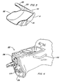
- Fig. 3 is perspective view of the lubricant collecting means and outlet conduit; and
- Fig. 4 is a further view of the transmission showing the lubricant conducting means leading from the lubricant collecting means adjacent the gear cluster source to the power input end of the transmission for delivery to the pocket bearing.
- Fig. 1 is typical view of the power input end of an automotive transmission in which the power from the engine (not shown) is delivered to the
output shaft 10. The enlarged end of theshaft 10 forms a drive gear 11 which meshes with a driven gear (not shown, but of well known character). The drive gear 11 encloses the power input end of atransmission shaft 12 which projects into the space in the drive gear 11. The pocket bearingassembly 13 is composed of aninner ring 13A on theshaft 12 and anouter race 13B in the gear 11 on theshaft 10, and between these shafts is a lubricant collecting cavity C. Theinput shaft adapter 14 is formed with suitable means to accommodate afurther bearing assembly 15 for theshaft 10, as well as aseal 16. - In the view of Fig. 1, there is the usual lubricant splash collection port 17 which opens from the interior of
input shaft adapter 14 to alubricant collecting space 18 which directs lubricant into thebearing cavity 19 adjacent other seal means 20 which prevents oil from enteringbearing 15. Thecavity 19 is in communication bydrilled ports 21 with the pocket bearing 13 so that lubricant in the cavity furnishes bearing 13 with lubricant before it exits back to the transmission sump. Lubricant cannot be brought in from the transmission area beyond and to the right of theshaft 12 because of shifting mechanisms, synchronizers and other gears. The problem with this normal arrangement of lubricant for the pocket bearing 13 is that when the transmission is tilted up, as when the vehicle is moved up an incline, some inclines being of 20° or more, the pocket bearing is starved for lubricant at the worst possible operating condition when the torque demands of the drive are greatest. - The preferred embodiment for solving the pocket bearing lubrication problem is seen in Figs. 1, 2, 3 and 4 where a source of lubricant under pressure or by force feed flow is associated with a
conduit 22 connected into thecavity 19. Tracing that conduit 22 back toward theoutput end 23 of the transmission assembly, it can be appreciated that it enters the housing wall in the vicinity of theend housing 24 of the transmission (see Fig. 4). - The details of the lubricant feed system are shown in Fig. 2, 3 and 4. The
housing 24 has the rear end cover removed to show the lubricant pumping means in the nature of agear cluster 25 in which amain gear 26 meshes withsatellite gears housing 24. When the cover is in place on thehousing 24 lubricant is retained therein regardless of the inclination of the vehicle. - An important member of the lubricating system is seen in Fig. 3, and its position in the system is seen in Fig. 2. That member or collecting scoop is a
curved pan 30 havingsides conduit 22. The spacing of thesides principal gear 26, and the entrance end ofconduit 22 is partially confined by an overhanging lip 33 so that the lubricant thrown upwardly along the curved surface of thepan 30 is turned into theconduit 22 with considerable force sufficient to cause the lubricant to traverse theconduit 22 and reach the pocket bearing 13. - The present disclosure shows the
lubricant conducting conduit 22 to be partially separate from the housing wall of the transmission. However, it is understood that the wall may have an internal passage or series of connected passages for delivering lubricant to the pocket bearing. It is seen in Fig. 1 that the cavity C in front of thetransmission shaft 12 receives and collects lubricant that will ultimately pass through the pocket bearing 13. When the clutch is engaged theprincipal pumping gear 26 is constantly rotating so lubricant will be delivered to the cavity C to assure adequate lubricant for the pocket bearing under transmission operating conditions. - In Fig. 1 it can be seen that the usual arrangement of
lubricant catch basin 18 is intended to supply the pocket bearing. The problem with that provision is that when the vehicle is moving up an incline or steep grade the lubricant migrates to the rear or away from the passage 17. The incline position is one in which the axis of theshaft 10 is tilted up from the left end. When that happens the gears in the front of the transmission do not dip into the lubricant and nothing reaches the passage 17 so the pocket bearing 13 is starved for lubricant. - The present invention overcomes the problem of the prior provisions and delivers adequate lubricant to the pocket bearing 13 regardless of the position of the vehicle. Thus, there is increased pressure in and flow of lubricant to the pocket bearing in a significant amount.
Claims (1)
Applications Claiming Priority (2)
| Application Number | Priority Date | Filing Date | Title |
|---|---|---|---|
| US83396786A | 1986-03-04 | 1986-03-04 | |
| US833967 | 2001-04-11 |
Publications (3)
| Publication Number | Publication Date |
|---|---|
| EP0237862A2 EP0237862A2 (en) | 1987-09-23 |
| EP0237862A3 EP0237862A3 (en) | 1988-05-11 |
| EP0237862B1 true EP0237862B1 (en) | 1991-10-09 |
Family
ID=25265760
Family Applications (1)
| Application Number | Title | Priority Date | Filing Date |
|---|---|---|---|
| EP87102955A Expired - Lifetime EP0237862B1 (en) | 1986-03-04 | 1987-03-02 | Lubrication system for automotive transmission pocket bearing |
Country Status (4)
| Country | Link |
|---|---|
| US (1) | US4842100A (en) |
| EP (1) | EP0237862B1 (en) |
| JP (1) | JPS62204097A (en) |
| DE (1) | DE3773514D1 (en) |
Families Citing this family (21)
| Publication number | Priority date | Publication date | Assignee | Title |
|---|---|---|---|---|
| DE4007881A1 (en) * | 1990-03-13 | 1991-09-19 | Skf Gmbh | Mounting assembly for shaft |
| US5810116A (en) * | 1997-06-04 | 1998-09-22 | New Venture Gear, Inc. | Bearing lubrication mechanism |
| US6021868A (en) * | 1997-09-02 | 2000-02-08 | Eaton Corporation | Mechanical transmission cooling and lubrication using associated engine systems |
| US6186277B1 (en) | 1998-12-02 | 2001-02-13 | Chrysler Corporation | Front axle differential bearing cap and lubrication/cooling method |
| US6334713B1 (en) | 1999-03-23 | 2002-01-01 | Roller Bearing Industries, Inc. | Bearing assembly having an improved wear ring liner |
| AU6908900A (en) | 1999-08-16 | 2001-03-13 | Roller Bearing Industries, Inc. | Bearing seal |
| US6964320B2 (en) * | 2003-01-28 | 2005-11-15 | Torque-Traction Technologies, Inc. | Lubrication arrangement for final drive unit |
| GB0325214D0 (en) * | 2003-10-29 | 2003-12-03 | Eaton Corp | Gearbox lubrication |
| JP2008115992A (en) * | 2006-11-07 | 2008-05-22 | Aisin Ai Co Ltd | Lubricating structure of transmission |
| US7861827B2 (en) * | 2007-11-02 | 2011-01-04 | General Electric Company | Oil manifold for lubricating bearings |
| US8356695B2 (en) * | 2009-11-17 | 2013-01-22 | Cnh America Llc | Method and apparatus for oiling splines in a bevel gearbox |
| DE102009059828A1 (en) * | 2009-12-21 | 2011-06-22 | GM Global Technology Operations LLC, ( n. d. Ges. d. Staates Delaware ), Mich. | Drive unit of a gearbox |
| JP5958877B2 (en) * | 2011-02-25 | 2016-08-02 | 住友電気工業株式会社 | Reactor, converter, and power converter |
| US9429224B2 (en) * | 2014-02-17 | 2016-08-30 | Deere & Company | Gearbox lubrication system |
| DE102014007540A1 (en) * | 2014-05-22 | 2015-11-26 | Daimler Ag | transmission device |
| CN106195127A (en) * | 2015-05-07 | 2016-12-07 | 中车北京南口机械有限公司 | Gear-box and rail vehicle |
| US9772027B2 (en) | 2015-10-08 | 2017-09-26 | GM Global Technology Operations LLC | Variable baffle that reduces oil at the gear mesh |
| DE102021206607B3 (en) * | 2021-06-25 | 2022-10-20 | Vitesco Technologies Germany Gmbh | Oil distributor, final drive and motor vehicle |
| US12215774B2 (en) * | 2022-11-28 | 2025-02-04 | Dana Italia S.R.L. | Systems and methods for gearbox fluid reservoir |
| DE102023211492A1 (en) * | 2023-11-20 | 2025-05-22 | Zf Friedrichshafen Ag | Oil guide arrangement for a gearbox |
| EP4617529A1 (en) * | 2024-03-13 | 2025-09-17 | Deere & Company | Spur gear transmission |
Citations (2)
| Publication number | Priority date | Publication date | Assignee | Title |
|---|---|---|---|---|
| US4221279A (en) * | 1978-12-11 | 1980-09-09 | Dana Corporation | Centrifugal lubrication system for transmission pocket bearing |
| US4227427A (en) * | 1977-09-08 | 1980-10-14 | Dana Corporation | Drive unit assembly |
Family Cites Families (9)
| Publication number | Priority date | Publication date | Assignee | Title |
|---|---|---|---|---|
| US2011559A (en) * | 1935-02-08 | 1935-08-20 | Timken Roller Bearing Co | Lubricating device |
| GB764860A (en) * | 1953-10-26 | 1957-01-02 | Napier & Son Ltd | Bearing assemblies and the lubrication thereof |
| DE2433990A1 (en) * | 1973-07-17 | 1975-02-13 | Rolls Royce 1971 Ltd | DIFFERENTIAL GEARS IN PARTICULAR FOR LOCOMOTIVES |
| FR2314395A1 (en) * | 1975-06-11 | 1977-01-07 | Siemens Ag | LUBRICATION DEVICE FOR BEARINGS AT HIGH ROTATION SPEEDS |
| US4359142A (en) * | 1979-02-08 | 1982-11-16 | Dana Corporation | Impeller lubrication system for transmission pocket bearing |
| JPS5829426B2 (en) * | 1979-10-22 | 1983-06-22 | トヨタ自動車株式会社 | Gear transmission bearing lubrication mechanism |
| JPS5743175Y2 (en) * | 1980-01-21 | 1982-09-22 | ||
| JPS6325421Y2 (en) * | 1980-04-03 | 1988-07-11 | ||
| US4525995A (en) * | 1983-04-04 | 1985-07-02 | Williams International Corporation | Oil scavening system for gas turbine engine |
-
1986
- 1986-07-24 JP JP61172952A patent/JPS62204097A/en active Pending
-
1987
- 1987-03-02 EP EP87102955A patent/EP0237862B1/en not_active Expired - Lifetime
- 1987-03-02 DE DE8787102955T patent/DE3773514D1/en not_active Expired - Lifetime
- 1987-11-19 US US07/122,922 patent/US4842100A/en not_active Expired - Fee Related
Patent Citations (2)
| Publication number | Priority date | Publication date | Assignee | Title |
|---|---|---|---|---|
| US4227427A (en) * | 1977-09-08 | 1980-10-14 | Dana Corporation | Drive unit assembly |
| US4221279A (en) * | 1978-12-11 | 1980-09-09 | Dana Corporation | Centrifugal lubrication system for transmission pocket bearing |
Also Published As
| Publication number | Publication date |
|---|---|
| DE3773514D1 (en) | 1991-11-14 |
| EP0237862A2 (en) | 1987-09-23 |
| EP0237862A3 (en) | 1988-05-11 |
| JPS62204097A (en) | 1987-09-08 |
| US4842100A (en) | 1989-06-27 |
Similar Documents
| Publication | Publication Date | Title |
|---|---|---|
| EP0237862A2 (en) | Lubrication system for automotive transmission pocket bearing | |
| CN113316694B (en) | Transmission device | |
| US12429128B2 (en) | Oil duct part to be mounted in a transmission, and transmission comprising an oil duct part | |
| US4231266A (en) | Lubricating device for power transmission unit | |
| US3738452A (en) | Lubricating arrangement for change-speed transmissions | |
| US4327598A (en) | Gear transmission apparatus for an automobile | |
| EP0566013B1 (en) | Lubrication system for tandem axle assembly | |
| US5946971A (en) | Oiling system in power transmission | |
| US12410860B2 (en) | Oil duct part to be mounted in a transmission | |
| GB2166816A (en) | Transmission lubrication | |
| US4719768A (en) | Circular knitting machine, in particular for hose knitting, with continuous cycle lubrication | |
| JPH0658129B2 (en) | Transmission air breather | |
| US5044895A (en) | Oil supply device for a rotary machine | |
| US4091905A (en) | Sump oil transfer system | |
| EP0148639A2 (en) | Lubrication arrangement in change-speed gearing assembly | |
| US5704331A (en) | Engine accessory drive | |
| CN218377626U (en) | Axle lubricating structure and vehicle with same | |
| JPS62258262A (en) | Lubrication structure for transfer device | |
| GB2042650A (en) | Gear Box with Lubricant Evacuation System | |
| JP4123925B2 (en) | Transmission lubrication structure | |
| JPH05180308A (en) | Lubrication structure of the differential gear in the housing | |
| JPH0262413B2 (en) | ||
| JPH08113053A (en) | Lubrication system for power takeoff | |
| JP2000110923A (en) | Transaxle lubrication structure | |
| WO2020129364A1 (en) | Gear case structure |
Legal Events
| Date | Code | Title | Description |
|---|---|---|---|
| PUAI | Public reference made under article 153(3) epc to a published international application that has entered the european phase |
Free format text: ORIGINAL CODE: 0009012 |
|
| AK | Designated contracting states |
Kind code of ref document: A2 Designated state(s): DE FR GB SE |
|
| PUAL | Search report despatched |
Free format text: ORIGINAL CODE: 0009013 |
|
| AK | Designated contracting states |
Kind code of ref document: A3 Designated state(s): DE FR GB SE |
|
| 17P | Request for examination filed |
Effective date: 19881028 |
|
| 17Q | First examination report despatched |
Effective date: 19890915 |
|
| GRAA | (expected) grant |
Free format text: ORIGINAL CODE: 0009210 |
|
| AK | Designated contracting states |
Kind code of ref document: B1 Designated state(s): DE FR GB SE |
|
| REF | Corresponds to: |
Ref document number: 3773514 Country of ref document: DE Date of ref document: 19911114 |
|
| ET | Fr: translation filed | ||
| PGFP | Annual fee paid to national office [announced via postgrant information from national office to epo] |
Ref country code: FR Payment date: 19920210 Year of fee payment: 6 |
|
| PGFP | Annual fee paid to national office [announced via postgrant information from national office to epo] |
Ref country code: SE Payment date: 19920217 Year of fee payment: 6 |
|
| PGFP | Annual fee paid to national office [announced via postgrant information from national office to epo] |
Ref country code: DE Payment date: 19920219 Year of fee payment: 6 |
|
| PLBE | No opposition filed within time limit |
Free format text: ORIGINAL CODE: 0009261 |
|
| STAA | Information on the status of an ep patent application or granted ep patent |
Free format text: STATUS: NO OPPOSITION FILED WITHIN TIME LIMIT |
|
| 26N | No opposition filed | ||
| PG25 | Lapsed in a contracting state [announced via postgrant information from national office to epo] |
Ref country code: SE Effective date: 19930303 |
|
| PG25 | Lapsed in a contracting state [announced via postgrant information from national office to epo] |
Ref country code: FR Effective date: 19931130 |
|
| PG25 | Lapsed in a contracting state [announced via postgrant information from national office to epo] |
Ref country code: DE Effective date: 19931201 |
|
| REG | Reference to a national code |
Ref country code: FR Ref legal event code: ST |
|
| PGFP | Annual fee paid to national office [announced via postgrant information from national office to epo] |
Ref country code: GB Payment date: 19940216 Year of fee payment: 8 |
|
| EUG | Se: european patent has lapsed |
Ref document number: 87102955.9 Effective date: 19931008 |
|
| PG25 | Lapsed in a contracting state [announced via postgrant information from national office to epo] |
Ref country code: GB Effective date: 19950302 |
|
| GBPC | Gb: european patent ceased through non-payment of renewal fee |
Effective date: 19950302 |