EP0237828A2 - Batterie aus Natrium-Schwefel-Akkumulatoren für räumliche Verwendungen - Google Patents
Batterie aus Natrium-Schwefel-Akkumulatoren für räumliche Verwendungen Download PDFInfo
- Publication number
- EP0237828A2 EP0237828A2 EP87102426A EP87102426A EP0237828A2 EP 0237828 A2 EP0237828 A2 EP 0237828A2 EP 87102426 A EP87102426 A EP 87102426A EP 87102426 A EP87102426 A EP 87102426A EP 0237828 A2 EP0237828 A2 EP 0237828A2
- Authority
- EP
- European Patent Office
- Prior art keywords
- battery
- battery according
- radiator
- accumulators
- thermal
- Prior art date
- Legal status (The legal status is an assumption and is not a legal conclusion. Google has not performed a legal analysis and makes no representation as to the accuracy of the status listed.)
- Granted
Links
- BNOODXBBXFZASF-UHFFFAOYSA-N [Na].[S] Chemical compound [Na].[S] BNOODXBBXFZASF-UHFFFAOYSA-N 0.000 title claims description 8
- 229910052782 aluminium Inorganic materials 0.000 claims description 7
- XAGFODPZIPBFFR-UHFFFAOYSA-N aluminium Chemical compound [Al] XAGFODPZIPBFFR-UHFFFAOYSA-N 0.000 claims description 7
- 239000004020 conductor Substances 0.000 claims description 4
- 238000010438 heat treatment Methods 0.000 claims description 4
- 239000010445 mica Substances 0.000 claims description 4
- 229910052618 mica group Inorganic materials 0.000 claims description 4
- 239000000615 nonconductor Substances 0.000 claims description 4
- RYGMFSIKBFXOCR-UHFFFAOYSA-N Copper Chemical compound [Cu] RYGMFSIKBFXOCR-UHFFFAOYSA-N 0.000 claims description 2
- FYYHWMGAXLPEAU-UHFFFAOYSA-N Magnesium Chemical compound [Mg] FYYHWMGAXLPEAU-UHFFFAOYSA-N 0.000 claims description 2
- BQCADISMDOOEFD-UHFFFAOYSA-N Silver Chemical compound [Ag] BQCADISMDOOEFD-UHFFFAOYSA-N 0.000 claims description 2
- 229910052802 copper Inorganic materials 0.000 claims description 2
- 239000010949 copper Substances 0.000 claims description 2
- 239000011810 insulating material Substances 0.000 claims description 2
- 239000011777 magnesium Substances 0.000 claims description 2
- 229910052749 magnesium Inorganic materials 0.000 claims description 2
- 229910052709 silver Inorganic materials 0.000 claims description 2
- 239000004332 silver Substances 0.000 claims description 2
- 230000001105 regulatory effect Effects 0.000 abstract description 5
- 229910052751 metal Inorganic materials 0.000 description 7
- 239000002184 metal Substances 0.000 description 7
- 239000003570 air Substances 0.000 description 5
- 238000010586 diagram Methods 0.000 description 3
- 239000011521 glass Substances 0.000 description 3
- 239000007788 liquid Substances 0.000 description 3
- PNEYBMLMFCGWSK-UHFFFAOYSA-N Alumina Chemical compound [O-2].[O-2].[O-2].[Al+3].[Al+3] PNEYBMLMFCGWSK-UHFFFAOYSA-N 0.000 description 2
- DGAQECJNVWCQMB-PUAWFVPOSA-M Ilexoside XXIX Chemical compound C[C@@H]1CC[C@@]2(CC[C@@]3(C(=CC[C@H]4[C@]3(CC[C@@H]5[C@@]4(CC[C@@H](C5(C)C)OS(=O)(=O)[O-])C)C)[C@@H]2[C@]1(C)O)C)C(=O)O[C@H]6[C@@H]([C@H]([C@@H]([C@H](O6)CO)O)O)O.[Na+] DGAQECJNVWCQMB-PUAWFVPOSA-M 0.000 description 2
- 239000011324 bead Substances 0.000 description 2
- 239000007789 gas Substances 0.000 description 2
- 239000011734 sodium Substances 0.000 description 2
- 229910052708 sodium Inorganic materials 0.000 description 2
- 229910000873 Beta-alumina solid electrolyte Inorganic materials 0.000 description 1
- 229910001209 Low-carbon steel Inorganic materials 0.000 description 1
- NINIDFKCEFEMDL-UHFFFAOYSA-N Sulfur Chemical compound [S] NINIDFKCEFEMDL-UHFFFAOYSA-N 0.000 description 1
- 239000012080 ambient air Substances 0.000 description 1
- 230000015572 biosynthetic process Effects 0.000 description 1
- OJIJEKBXJYRIBZ-UHFFFAOYSA-N cadmium nickel Chemical compound [Ni].[Cd] OJIJEKBXJYRIBZ-UHFFFAOYSA-N 0.000 description 1
- 239000002775 capsule Substances 0.000 description 1
- 239000012809 cooling fluid Substances 0.000 description 1
- 239000000112 cooling gas Substances 0.000 description 1
- 230000006735 deficit Effects 0.000 description 1
- 238000007599 discharging Methods 0.000 description 1
- 230000000694 effects Effects 0.000 description 1
- 238000010292 electrical insulation Methods 0.000 description 1
- 239000012777 electrically insulating material Substances 0.000 description 1
- 230000002349 favourable effect Effects 0.000 description 1
- 239000000446 fuel Substances 0.000 description 1
- 239000012212 insulator Substances 0.000 description 1
- 238000000034 method Methods 0.000 description 1
- 239000011593 sulfur Substances 0.000 description 1
- 229910052717 sulfur Inorganic materials 0.000 description 1
- 238000009834 vaporization Methods 0.000 description 1
- 230000008016 vaporization Effects 0.000 description 1
- 238000003466 welding Methods 0.000 description 1
Images


Classifications
-
- H—ELECTRICITY
- H01—ELECTRIC ELEMENTS
- H01M—PROCESSES OR MEANS, e.g. BATTERIES, FOR THE DIRECT CONVERSION OF CHEMICAL ENERGY INTO ELECTRICAL ENERGY
- H01M10/00—Secondary cells; Manufacture thereof
- H01M10/36—Accumulators not provided for in groups H01M10/05-H01M10/34
- H01M10/39—Accumulators not provided for in groups H01M10/05-H01M10/34 working at high temperature
- H01M10/3909—Sodium-sulfur cells
-
- H—ELECTRICITY
- H01—ELECTRIC ELEMENTS
- H01M—PROCESSES OR MEANS, e.g. BATTERIES, FOR THE DIRECT CONVERSION OF CHEMICAL ENERGY INTO ELECTRICAL ENERGY
- H01M10/00—Secondary cells; Manufacture thereof
- H01M10/60—Heating or cooling; Temperature control
- H01M10/61—Types of temperature control
- H01M10/613—Cooling or keeping cold
-
- H—ELECTRICITY
- H01—ELECTRIC ELEMENTS
- H01M—PROCESSES OR MEANS, e.g. BATTERIES, FOR THE DIRECT CONVERSION OF CHEMICAL ENERGY INTO ELECTRICAL ENERGY
- H01M10/00—Secondary cells; Manufacture thereof
- H01M10/60—Heating or cooling; Temperature control
- H01M10/64—Heating or cooling; Temperature control characterised by the shape of the cells
- H01M10/643—Cylindrical cells
-
- H—ELECTRICITY
- H01—ELECTRIC ELEMENTS
- H01M—PROCESSES OR MEANS, e.g. BATTERIES, FOR THE DIRECT CONVERSION OF CHEMICAL ENERGY INTO ELECTRICAL ENERGY
- H01M10/00—Secondary cells; Manufacture thereof
- H01M10/60—Heating or cooling; Temperature control
- H01M10/65—Means for temperature control structurally associated with the cells
- H01M10/653—Means for temperature control structurally associated with the cells characterised by electrically insulating or thermally conductive materials
-
- H—ELECTRICITY
- H01—ELECTRIC ELEMENTS
- H01M—PROCESSES OR MEANS, e.g. BATTERIES, FOR THE DIRECT CONVERSION OF CHEMICAL ENERGY INTO ELECTRICAL ENERGY
- H01M10/00—Secondary cells; Manufacture thereof
- H01M10/60—Heating or cooling; Temperature control
- H01M10/65—Means for temperature control structurally associated with the cells
- H01M10/655—Solid structures for heat exchange or heat conduction
- H01M10/6554—Rods or plates
- H01M10/6555—Rods or plates arranged between the cells
-
- Y—GENERAL TAGGING OF NEW TECHNOLOGICAL DEVELOPMENTS; GENERAL TAGGING OF CROSS-SECTIONAL TECHNOLOGIES SPANNING OVER SEVERAL SECTIONS OF THE IPC; TECHNICAL SUBJECTS COVERED BY FORMER USPC CROSS-REFERENCE ART COLLECTIONS [XRACs] AND DIGESTS
- Y02—TECHNOLOGIES OR APPLICATIONS FOR MITIGATION OR ADAPTATION AGAINST CLIMATE CHANGE
- Y02E—REDUCTION OF GREENHOUSE GAS [GHG] EMISSIONS, RELATED TO ENERGY GENERATION, TRANSMISSION OR DISTRIBUTION
- Y02E60/00—Enabling technologies; Technologies with a potential or indirect contribution to GHG emissions mitigation
- Y02E60/10—Energy storage using batteries
Definitions
- the present invention relates to a sodium-sulfur storage battery for space applications.
- a gas regulating device can be used in which the circulation of gas, generally air, drains calories towards the outside by means of an air / air exchanger or by admitting cold air and by evacuating hot air in a ratio which is a function of the power to be dissipated.
- Liquid regulation devices are also known in which the latent heat of vaporization is used; the vapor formed by absorbing calories is recondensed in an ambient air exchanger.
- the first type of device leads to a lower weight than the second type, but it is less effective against the formation of hot spots.
- the second type of device has a smaller volume, but none of the three types of device is capable of being selected for reasons of weight and bulk in space applications.
- the present invention aims to solve the problem of thermal regulation of a sodium-sulfur battery for said applications.
- the present invention relates to a sodium-sulfur accumulator battery for space applications comprising a plurality of juxtaposed cylindrical accumulators, one base of which carries a terminal of a first polarity and the container constitutes a terminal of a second polarity, electrically connected by metal plates at the level of said bases and of said containers, characterized in that it comprises a thermal regulation device comprising: - a substantially parallelepiped insulated enclosure, one wall of which has a large opening, - pads of thermal conductive material in thermal contact, by an electrical insulator interposed, on the one hand with said containers and on the other hand with a radiator common to all the accumulators, and closing said opening of the heat-insulated enclosure, - heating resistors interposed between the accumulators, capable of being supplied by a source external to the battery, and controlled by the internal temperature of the enclosure, the dimensions and the nature of said radiator as well as the control of the supply of said resistors being such that the temperature of the battery is maintained between two extreme temperatures of 290 and
- super insulating walls with a thickness of around 3 cm are used for the heat-insulated enclosure, which may consist of compacted glass beads in which the vacuum prevails.
- the plates of thermal conductive material may be copper, silver, magnesium, but preferably aluminum.
- the electrical insulation inserted is preferably made of mica; it can also be made of polyimine, or paraphenylene-quinoxaline.
- the accumulator 1 visible in FIG. 1 comprises a cylinder 2 in second beta alumina open at its two ends; it is closed at its upper end by a disk 3 in alpha alumina and at its lower end by a disk 4 in alpha alumina.
- the tightness of the connections is obtained by glass seals or aluminum thermocompression.
- the reservoir thus formed is intended to receive liquid sodium 5 impregnated in sodium wicks.
- the disc 3 has a central bore for a metallic filling pipe 6 which also serves as a negative current collector.
- the end of the pipe 6 is closed by a hollow capsule 11, internally threaded, intended to receive the fixing screw of an electrical connection.
- the positive container 7 serving as an envelope for the accumulator and as a positive terminal, is constituted by a cylinder of chromium-plated mild steel tightly connected to the two discs 3 and 4 by annular metal parts 8 and 9 sealed by thermocompression.
- the container 7 contains sulfur 10.
- a storage battery 1 juxtaposed so as to form a parallelepiped module.
- This module is housed in a heat-insulated enclosure 20 with five walls, the base of this enclosure being closed by a metallic flat radiator 21.
- the lower bases of the accumulators 1 and the radiator 21 are electrically and thermally insulated by a sheet 22.
- the walls of the enclosure 20 are made of super-insulating material which may consist of compacted hollow glass beads where the vacuum prevails; their thickness is of the order of 3 centimeters.
- the planar radiator 21 is preferably made of black anodized aluminum and has an excellent emission coefficient.
- the electrical insulating sheet 22 is preferably made of mica.
- the electrical insulators also act as thermal insulators for the bases of the containers in order to prevent overcooling. important at this level.
- FIG. 3 shows accumulators 1 of FIG. 2 referenced 31, 41 and 51. Their upper bases carry negative terminals 32, 42, 52, connected by metal connections 23, 24. Their positive containers 33, 43, 53 are electrically connected by thin metal plates 25, 26.
- the negative connections 24 are connected to the positive connections 25 etc.
- the metal plate 26 is connected to the positive output of the battery, while at the other end of the battery, the last group of negative terminals of the elements is connected to the negative output of the battery.
- Each accumulator such as the accumulator 51, is associated with an aluminum plate 54 of trapezoidal shape, making the entire height of the accumulator and wider at the bottom than at the top.
- the width of the aluminum plate increases for example from 10 mm to 20 mm.
- This plate passes through the insulating sheet 22, and is connected, for example by welding, to the radiator 21 which itself is electrically insulated from the metal plates 25, 26.
- a plate 55 made of electrically insulating material, such as mica, is interposed between positive collectors such as 25, 26 and platelets 54; it also plays a thermal role because it avoids hot spots.
- the calories emitted by the accumulators are therefore collected along the walls of each of their containers by the plates 54 and drained to the radiator 21 which transfers them to the outside environment.
- the regulating device according to the invention further comprises heating resistors 64, 65, 66, plated on the metal connection plate 26 and supplied by an external source, for example, a solar panel.
- This power supply is controlled by the temperature of the accumulators, which can only operate between 290 ° C and 380 ° C.
- these resistors are used for the initial heating of the battery.
- the assembly formed by the accumulators and their regulating accessories can be easily immobilized in the insulated enclosure.
- Example a 1.6 kWh battery according to the invention comprises sixty sodium-sulfur accumulators with a nominal capacity of 12 Ah grouped in fifteen rows of four accumulators in parallel; the module volume is 6.9 dm3.
- the total weight of the battery and its thermal regulation system is 14.6 kg, leading to a mass energy of 88 Wh / Kg and a volume energy of 106 Wh / dm3.
- this battery In a first mode of use, this battery is placed in an observation satellite, or a shuttle, in low orbit. It works continuously. Each cycle corresponds to a rotation around the earth and involves a charge of one hour at 40 amps and a discharge of 40 minutes at 60 amps.
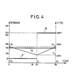
- the thermoneutral voltage being on average, for the considered application of 32.6 Volts, the average power to be dissipated is 48 watts during charging and 324 watts during discharging.
- the constant surface radiator has an average temperature of around 600 K. It constantly dissipates 160 watts.
- the time t corresponding to a cycle is shown on the abscissa; t0 corresponds to the start of the charge, t1 to the end of the charge and the start of the discharge, and t2 to the end of the discharge. On the ordinate there is a scale W in watts indicating the dissipated power, and a scale of temperature T in degrees Celsius.
- the regulation resistors can therefore be supplied so as to prevent the temperature of the battery from falling below the limit value of 290 ° C.
- this intervention is only necessary in the event of an accidental deviation due, for example, to a change of regime.
- the thermal cycle is self-balanced and stable over time.
- the radiator emits approximately 160 watts (curve R) and the battery dissipates 48 watts (curve C).
- the 112 W deficit is then taken from the battery components whose total thermal capacity is 13,440 J / ° C, which has the effect of increasing the temperature from 340 ° C to 310 ° C.
- the resistors do not function do not.
- the radiator always emits 160 watts, the battery dissipates 324 watts (curve D); the excess of 164 W this time causes the temperature of the battery to rise by 30 ° C after 40 minutes, thus bringing the thermal cycle back to its starting point.
- the complete operating cycle lasts 24 hours.
- the charging period between t0 and t1 lasts at least 2.8 hours (t0 to t1 min), and maximum 10 hours (t0 to t1 max).
- the charging period is followed by a rest period (t1 min to t ⁇ 1 min) in the first case, and (t1 max to t ⁇ 1 max) in the second case.
- the discharge period lasts at least 21 minutes (t ⁇ 1 min to t2), and maximum 1 hour 12 minutes (t ⁇ 1 max to t2).
- the radiator is chosen so as to constantly dissipate 11.3 watts (curve G).
- the regulation resistors operate in such a way that the temperature T1 (T1 min, T1 max) at the end of charging is not less than 305 ° C. It is the same during the rest period.
- the battery dissipates approximately 150 watts (curve H); at the end of discharge, its temperature T2 is of the order of 340 ° C.
- a battery according to the invention has many advantages. It has no moving devices. It is very compact because there is no need to provide space for forced circulation of cooling gas or convection of vaporized liquid.
- the operating temperature ( ⁇ 600 K) of sodium-sulfur accumulators is extremely favorable compared to that of other generators, such as fuel cells, or accumulators nickel-cadmium which operate around 300 K; indeed the energy emitted by the radiator being proportional to T4 (K), it is possible to divide the surface of this radiator by 16 to obtain the same temperature regulation.
- the device provided by the invention is in modular form, which makes it possible to easily produce different types of batteries meeting various specifications.
- traditional batteries on the contrary, it is necessary to design a type for each specification.
Landscapes
- Engineering & Computer Science (AREA)
- Manufacturing & Machinery (AREA)
- Chemical & Material Sciences (AREA)
- Chemical Kinetics & Catalysis (AREA)
- Electrochemistry (AREA)
- General Chemical & Material Sciences (AREA)
- Secondary Cells (AREA)
- Battery Mounting, Suspending (AREA)
Priority Applications (1)
| Application Number | Priority Date | Filing Date | Title |
|---|---|---|---|
| AT87102426T ATE70923T1 (de) | 1986-02-21 | 1987-02-20 | Batterie aus natrium-schwefel-akkumulatoren fuer raeumliche verwendungen. |
Applications Claiming Priority (2)
| Application Number | Priority Date | Filing Date | Title |
|---|---|---|---|
| FR8602408 | 1986-02-21 | ||
| FR8602408A FR2595009A1 (fr) | 1986-02-21 | 1986-02-21 | Batterie d'accumulateurs sodium-soufre pour applications spatiales |
Publications (3)
| Publication Number | Publication Date |
|---|---|
| EP0237828A2 true EP0237828A2 (de) | 1987-09-23 |
| EP0237828A3 EP0237828A3 (en) | 1988-03-30 |
| EP0237828B1 EP0237828B1 (de) | 1991-12-27 |
Family
ID=9332393
Family Applications (1)
| Application Number | Title | Priority Date | Filing Date |
|---|---|---|---|
| EP19870102426 Expired - Lifetime EP0237828B1 (de) | 1986-02-21 | 1987-02-20 | Batterie aus Natrium-Schwefel-Akkumulatoren für räumliche Verwendungen |
Country Status (6)
| Country | Link |
|---|---|
| EP (1) | EP0237828B1 (de) |
| AT (1) | ATE70923T1 (de) |
| DE (1) | DE3775437D1 (de) |
| ES (1) | ES2028805T3 (de) |
| FR (1) | FR2595009A1 (de) |
| GR (1) | GR3003919T3 (de) |
Cited By (4)
| Publication number | Priority date | Publication date | Assignee | Title |
|---|---|---|---|---|
| WO1989000344A3 (en) * | 1987-07-03 | 1989-01-26 | Chloride Silent Power Ltd | Batteries |
| EP0439661A1 (de) * | 1989-01-19 | 1991-08-07 | Hughes Aircraft Company | Natrium-Schwefelzelle, verwendbar in der Schwerelosigkeit |
| WO2008137232A1 (en) * | 2007-05-07 | 2008-11-13 | General Electric Company | Battery mechanical packaging |
| US10218042B2 (en) | 2013-01-08 | 2019-02-26 | Siemens Aktiengesellschaft | Heat dissipating device for an electrochemical storage device |
Families Citing this family (1)
| Publication number | Priority date | Publication date | Assignee | Title |
|---|---|---|---|---|
| DE102011007069B4 (de) * | 2011-04-08 | 2018-11-22 | Continental Automotive Gmbh | Elektrischer Energiespeicher mit mehreren Zellen und wenigstens einem zwischen den Zellen angeordneten Kühlelement und dessen Verwendung |
Family Cites Families (5)
| Publication number | Priority date | Publication date | Assignee | Title |
|---|---|---|---|---|
| FR1061241A (fr) * | 1952-08-05 | 1954-04-09 | Accumulateurs Fixes | Batteries d'accumulateurs |
| US3823037A (en) * | 1972-07-20 | 1974-07-09 | Atomic Energy Commission | Implantable battery |
| JPS5991658A (ja) * | 1982-11-18 | 1984-05-26 | Japan Storage Battery Co Ltd | アルカリ蓄電池用モノブロツクタイプ電槽 |
| DE3242901A1 (de) * | 1982-11-20 | 1984-05-24 | Brown, Boveri & Cie Ag, 6800 Mannheim | Hochtemperatur-speicherbatterie |
| DE3340425C2 (de) * | 1983-11-09 | 1987-04-02 | Brown, Boveri & Cie Ag, 6800 Mannheim | Hochtemperatur-Speicherbatterie auf der Basis von Alkalimetall und Chalkogen |
-
1986
- 1986-02-21 FR FR8602408A patent/FR2595009A1/fr not_active Withdrawn
-
1987
- 1987-02-20 EP EP19870102426 patent/EP0237828B1/de not_active Expired - Lifetime
- 1987-02-20 ES ES87102426T patent/ES2028805T3/es not_active Expired - Lifetime
- 1987-02-20 AT AT87102426T patent/ATE70923T1/de not_active IP Right Cessation
- 1987-02-20 DE DE8787102426T patent/DE3775437D1/de not_active Expired - Lifetime
-
1992
- 1992-02-27 GR GR920400341T patent/GR3003919T3/el unknown
Cited By (5)
| Publication number | Priority date | Publication date | Assignee | Title |
|---|---|---|---|---|
| WO1989000344A3 (en) * | 1987-07-03 | 1989-01-26 | Chloride Silent Power Ltd | Batteries |
| US5034290A (en) * | 1987-07-03 | 1991-07-23 | Chloride Silent Power Limited | Batteries |
| EP0439661A1 (de) * | 1989-01-19 | 1991-08-07 | Hughes Aircraft Company | Natrium-Schwefelzelle, verwendbar in der Schwerelosigkeit |
| WO2008137232A1 (en) * | 2007-05-07 | 2008-11-13 | General Electric Company | Battery mechanical packaging |
| US10218042B2 (en) | 2013-01-08 | 2019-02-26 | Siemens Aktiengesellschaft | Heat dissipating device for an electrochemical storage device |
Also Published As
| Publication number | Publication date |
|---|---|
| EP0237828B1 (de) | 1991-12-27 |
| ES2028805T3 (es) | 1992-07-16 |
| GR3003919T3 (de) | 1993-03-16 |
| DE3775437D1 (de) | 1992-02-06 |
| ATE70923T1 (de) | 1992-01-15 |
| EP0237828A3 (en) | 1988-03-30 |
| FR2595009A1 (fr) | 1987-08-28 |
Similar Documents
| Publication | Publication Date | Title |
|---|---|---|
| EP3017498B1 (de) | Thermische steuervorrichtung der batterie eines elektrofahrzeugs | |
| EP2630688B1 (de) | Batterie für einen elektromotor eines kraftfahrzeugs | |
| EP3212503B1 (de) | Künstlicher satellit und verfahren zum füllen eines tanks eines treibgases des besagten künstlichen satelliten | |
| WO2020049248A1 (fr) | Module electrique comprenant une pluralite de cellules de batteries immergees dans un fluide dielectrique | |
| CA2667410A1 (fr) | Batterie electrique comprenant un systeme de conditionnement mecanique et thermique | |
| EP0531659A1 (de) | Elektrochemischer Generator mit hoher spezifischer Energie | |
| FR2936111A1 (fr) | Systeme photovoltaique a batterie et panneau photovoltaique integres | |
| EP3008772B1 (de) | Batteriepack für ein kraftfahrzeug | |
| EP0237828B1 (de) | Batterie aus Natrium-Schwefel-Akkumulatoren für räumliche Verwendungen | |
| WO2023126591A2 (fr) | Boîtier électrique pour aéronef | |
| WO2018167382A1 (fr) | Echangeur thermique et dispositif de régulation thermique d'au moins un élément de stockage d'énergie électrique | |
| EP2004977B1 (de) | Thermo-akustischer wandler und einen thermo-akustischen wandler umfassender generator zur erzeugung elektrischer energie | |
| EP3262362A1 (de) | Wärmeverwaltungsvorrichtung einer energiespeichereinheit | |
| FR3111691A1 (fr) | Dispositif thermique à PRESSION controlee alimente en fluide fusible | |
| WO2011080490A2 (fr) | Dispositif de chauffage central solaire a accumulation d'energie | |
| FR3154350A1 (fr) | Dispositif de stockage d'énergie électrique à double contrôle thermique et véhicule associé. | |
| FR2903058A1 (fr) | Dispositif compact d'alimentation electrique pour un vehicule automobile equipe de moyens de regulation de la temperature | |
| EP0116503B1 (de) | Wärmeaufnahmevorrichtung und Verfahren zu deren Herstellung | |
| FR2477688A1 (fr) | Perfectionnements apportes aux appareils de climatisation a fonctionnement autonome et servant a refroidir ou rechauffer un volume d'utilisation relativement grand | |
| FR2778271A1 (fr) | Dispositif de rechauffage a air pour une batterie de vehicule electrique ou hybride | |
| EP0021307A1 (de) | Wärmeaustauschvorrichtung zwischen wenigstens zwei Wärmequellen um sie auf verschiedenen Temperaturniveaus zu halten | |
| EP4629376A1 (de) | Batteriemodul für ein ausserirdisches fahrzeug | |
| EP4092796A1 (de) | Batteriemodul | |
| FR3151898A1 (fr) | Système de stockage d’énergie thermique comprenant un matériau a changement de phase et boucle de conditionnement thermique comprenant un tel système | |
| FR2895838A1 (fr) | Batterie electrique conditionnee en temperature par un materiau a changement de phase |
Legal Events
| Date | Code | Title | Description |
|---|---|---|---|
| PUAI | Public reference made under article 153(3) epc to a published international application that has entered the european phase |
Free format text: ORIGINAL CODE: 0009012 |
|
| AK | Designated contracting states |
Kind code of ref document: A2 Designated state(s): AT BE CH DE ES FR GB GR IT LI LU NL SE |
|
| PUAL | Search report despatched |
Free format text: ORIGINAL CODE: 0009013 |
|
| AK | Designated contracting states |
Kind code of ref document: A3 Designated state(s): AT BE CH DE ES FR GB GR IT LI LU NL SE |
|
| 17P | Request for examination filed |
Effective date: 19880929 |
|
| RAP1 | Party data changed (applicant data changed or rights of an application transferred) |
Owner name: ALCATEL ALSTHOM COMPAGNIE GENERALE D'ELECTRICITE |
|
| 17Q | First examination report despatched |
Effective date: 19910430 |
|
| GRAA | (expected) grant |
Free format text: ORIGINAL CODE: 0009210 |
|
| AK | Designated contracting states |
Kind code of ref document: B1 Designated state(s): AT BE CH DE ES FR GB GR IT LI LU NL SE |
|
| REF | Corresponds to: |
Ref document number: 70923 Country of ref document: AT Date of ref document: 19920115 Kind code of ref document: T |
|
| GBT | Gb: translation of ep patent filed (gb section 77(6)(a)/1977) | ||
| REF | Corresponds to: |
Ref document number: 3775437 Country of ref document: DE Date of ref document: 19920206 |
|
| ITF | It: translation for a ep patent filed | ||
| REG | Reference to a national code |
Ref country code: ES Ref legal event code: FG2A Ref document number: 2028805 Country of ref document: ES Kind code of ref document: T3 |
|
| PLBE | No opposition filed within time limit |
Free format text: ORIGINAL CODE: 0009261 |
|
| STAA | Information on the status of an ep patent application or granted ep patent |
Free format text: STATUS: NO OPPOSITION FILED WITHIN TIME LIMIT |
|
| REG | Reference to a national code |
Ref country code: GR Ref legal event code: FG4A Free format text: 3003919 |
|
| 26N | No opposition filed | ||
| PGFP | Annual fee paid to national office [announced via postgrant information from national office to epo] |
Ref country code: GB Payment date: 19931221 Year of fee payment: 8 |
|
| PGFP | Annual fee paid to national office [announced via postgrant information from national office to epo] |
Ref country code: GR Payment date: 19931227 Year of fee payment: 8 |
|
| PGFP | Annual fee paid to national office [announced via postgrant information from national office to epo] |
Ref country code: FR Payment date: 19931230 Year of fee payment: 8 Ref country code: AT Payment date: 19931230 Year of fee payment: 8 |
|
| PGFP | Annual fee paid to national office [announced via postgrant information from national office to epo] |
Ref country code: ES Payment date: 19940121 Year of fee payment: 8 |
|
| PGFP | Annual fee paid to national office [announced via postgrant information from national office to epo] |
Ref country code: CH Payment date: 19940124 Year of fee payment: 8 |
|
| PGFP | Annual fee paid to national office [announced via postgrant information from national office to epo] |
Ref country code: SE Payment date: 19940127 Year of fee payment: 8 |
|
| PGFP | Annual fee paid to national office [announced via postgrant information from national office to epo] |
Ref country code: BE Payment date: 19940210 Year of fee payment: 8 |
|
| PGFP | Annual fee paid to national office [announced via postgrant information from national office to epo] |
Ref country code: NL Payment date: 19940228 Year of fee payment: 8 Ref country code: LU Payment date: 19940228 Year of fee payment: 8 |
|
| EPTA | Lu: last paid annual fee | ||
| PGFP | Annual fee paid to national office [announced via postgrant information from national office to epo] |
Ref country code: DE Payment date: 19940416 Year of fee payment: 8 |
|
| EAL | Se: european patent in force in sweden |
Ref document number: 87102426.1 |
|
| PG25 | Lapsed in a contracting state [announced via postgrant information from national office to epo] |
Ref country code: LU Free format text: LAPSE BECAUSE OF NON-PAYMENT OF DUE FEES Effective date: 19950220 Ref country code: GB Effective date: 19950220 Ref country code: AT Effective date: 19950220 |
|
| PG25 | Lapsed in a contracting state [announced via postgrant information from national office to epo] |
Ref country code: SE Effective date: 19950221 Ref country code: ES Free format text: LAPSE BECAUSE OF NON-PAYMENT OF DUE FEES Effective date: 19950221 |
|
| PG25 | Lapsed in a contracting state [announced via postgrant information from national office to epo] |
Ref country code: LI Effective date: 19950228 Ref country code: CH Effective date: 19950228 Ref country code: BE Effective date: 19950228 |
|
| BERE | Be: lapsed |
Owner name: ALCATEL ALSTHOM CIE GENERALE D'ELECTRICITE Effective date: 19950228 |
|
| PG25 | Lapsed in a contracting state [announced via postgrant information from national office to epo] |
Ref country code: GR Free format text: THE PATENT HAS BEEN ANNULLED BY A DECISION OF A NATIONAL AUTHORITY Effective date: 19950831 |
|
| PG25 | Lapsed in a contracting state [announced via postgrant information from national office to epo] |
Ref country code: NL Effective date: 19950901 |
|
| GBPC | Gb: european patent ceased through non-payment of renewal fee |
Effective date: 19950220 |
|
| PG25 | Lapsed in a contracting state [announced via postgrant information from national office to epo] |
Ref country code: FR Effective date: 19951031 |
|
| REG | Reference to a national code |
Ref country code: GR Ref legal event code: MM2A Free format text: 3003919 |
|
| NLV4 | Nl: lapsed or anulled due to non-payment of the annual fee |
Effective date: 19950901 |
|
| PG25 | Lapsed in a contracting state [announced via postgrant information from national office to epo] |
Ref country code: DE Effective date: 19951101 |
|
| EUG | Se: european patent has lapsed |
Ref document number: 87102426.1 |
|
| REG | Reference to a national code |
Ref country code: FR Ref legal event code: ST |
|
| REG | Reference to a national code |
Ref country code: ES Ref legal event code: FD2A Effective date: 19990201 |
|
| PG25 | Lapsed in a contracting state [announced via postgrant information from national office to epo] |
Ref country code: IT Free format text: LAPSE BECAUSE OF NON-PAYMENT OF DUE FEES;WARNING: LAPSES OF ITALIAN PATENTS WITH EFFECTIVE DATE BEFORE 2007 MAY HAVE OCCURRED AT ANY TIME BEFORE 2007. THE CORRECT EFFECTIVE DATE MAY BE DIFFERENT FROM THE ONE RECORDED. Effective date: 20050220 |