EP0237646A2 - Hochdruck-Gasfüllventil für einen druckfesten Behälter - Google Patents
Hochdruck-Gasfüllventil für einen druckfesten Behälter Download PDFInfo
- Publication number
- EP0237646A2 EP0237646A2 EP86117992A EP86117992A EP0237646A2 EP 0237646 A2 EP0237646 A2 EP 0237646A2 EP 86117992 A EP86117992 A EP 86117992A EP 86117992 A EP86117992 A EP 86117992A EP 0237646 A2 EP0237646 A2 EP 0237646A2
- Authority
- EP
- European Patent Office
- Prior art keywords
- valve
- gas
- valve body
- fitting
- seal ring
- Prior art date
- Legal status (The legal status is an assumption and is not a legal conclusion. Google has not performed a legal analysis and makes no representation as to the accuracy of the status listed.)
- Granted
Links
Images
Classifications
-
- F—MECHANICAL ENGINEERING; LIGHTING; HEATING; WEAPONS; BLASTING
- F16—ENGINEERING ELEMENTS AND UNITS; GENERAL MEASURES FOR PRODUCING AND MAINTAINING EFFECTIVE FUNCTIONING OF MACHINES OR INSTALLATIONS; THERMAL INSULATION IN GENERAL
- F16K—VALVES; TAPS; COCKS; ACTUATING-FLOATS; DEVICES FOR VENTING OR AERATING
- F16K1/00—Lift valves or globe valves, i.e. cut-off apparatus with closure members having at least a component of their opening and closing motion perpendicular to the closing faces
- F16K1/30—Lift valves or globe valves, i.e. cut-off apparatus with closure members having at least a component of their opening and closing motion perpendicular to the closing faces specially adapted for pressure containers
- F16K1/301—Lift valves or globe valves, i.e. cut-off apparatus with closure members having at least a component of their opening and closing motion perpendicular to the closing faces specially adapted for pressure containers only shut-off valves, i.e. valves without additional means
- F16K1/303—Lift valves or globe valves, i.e. cut-off apparatus with closure members having at least a component of their opening and closing motion perpendicular to the closing faces specially adapted for pressure containers only shut-off valves, i.e. valves without additional means with a valve member, e.g. stem or shaft, passing through the seat
-
- F—MECHANICAL ENGINEERING; LIGHTING; HEATING; WEAPONS; BLASTING
- F16—ENGINEERING ELEMENTS AND UNITS; GENERAL MEASURES FOR PRODUCING AND MAINTAINING EFFECTIVE FUNCTIONING OF MACHINES OR INSTALLATIONS; THERMAL INSULATION IN GENERAL
- F16K—VALVES; TAPS; COCKS; ACTUATING-FLOATS; DEVICES FOR VENTING OR AERATING
- F16K1/00—Lift valves or globe valves, i.e. cut-off apparatus with closure members having at least a component of their opening and closing motion perpendicular to the closing faces
- F16K1/30—Lift valves or globe valves, i.e. cut-off apparatus with closure members having at least a component of their opening and closing motion perpendicular to the closing faces specially adapted for pressure containers
- F16K1/307—Additional means used in combination with the main valve
-
- F—MECHANICAL ENGINEERING; LIGHTING; HEATING; WEAPONS; BLASTING
- F23—COMBUSTION APPARATUS; COMBUSTION PROCESSES
- F23Q—IGNITION; EXTINGUISHING-DEVICES
- F23Q2/00—Lighters containing fuel, e.g. for cigarettes
- F23Q2/34—Component parts or accessories
- F23Q2/52—Filling devices
Definitions
- the present invention relates to a valve for use in filling a pressure resistant container with gas at an increased pressure.
- a pressure resistant container equipped with a gas filling valve as used in a gas lighter there are two kinds of gas filling valves, one having a gas depletion path provided therein, and the other having no gas depletion path.
- the object of the present invention is to provide a high-pressure gas filling valve structure which makes it easy to form an appropriate size of depletion path, positively preventing gas leakage and intrusion of dust particles to sealed portions in a pressure resistant container.
- a high-pressure gas filling valve for use in a pressure resistant container comprises: a reentrant valve chamber opening to the atmosphere at one end thereof and communicating with the inside space of the pressure resistant container at the other end of the valve chamber; a slidable valve body put in the valve chamber, the valve body having a neck of reduced diameter, a gas injection path opening to the atmosphere and extending short of the top of the valve body along the longitudinal central axis thereof, and valve outlet radially branching from the longitudinal gas injection path; a spring means for pushing the slidable valve body towards the opening end of the valve chamber; a valve fitting fixed to the valve chamber, accommodating the slidable valve body in the center hole of the valve fitting; an annular seat integrally connected to and inwardly projecting from the inner wall of the valve chamber in opposing relation to the top end of the valve fitting, leaving a given space therebetween; and a seal ring of an elastic material slidably fitted around the neck of the valve body, the seal ring being mov
- Such gas depletion path effectively controls the discharge of gas by means of the space existing in the opposing contact areas of the outer peripheral surface of the control ring and the inner wall of the valve chamber and the space existing in the opposing contact areas of the lower surface of the control ring and the top end of the valve fitting.
- the flow rate at which the gas is allowed to escape can be controlled by controlling the roughness of the contact areas of the opposing members and by controlling the pressure with which the control ring is pushed against the inner wall of the valve chamber and the valve fitting.
- Such gas depletion path appropriate for the purpose is easy to be formed, compared with the one which is formed with recourse to machining.
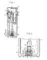
- a pressure resistant container 1 has a flame valve 2 provided at the top of the gas storage.
- the actuation of a gas lever 3 will cause ejection of gas from a flame nozzle 4.
- a piezoelectric element 5 is positioned next to the flame valve 2.
- the thumb-operated cap 6 is pushed down, the piezoelectric element 5 is subjected to compression to generate electricity at so high a voltage that an electric discharge appears between the discharge electrode 7 and the counter electrode of nozzle 4, thereby causing ignition.
- a lever-push 8 is fixed to the side of the piezoelectric element 5 for pushing the gas lever 3 in the course of descent of the piezoelectric element.
- a high-pressure gas filling valve 9 is mounted at the bottom of the gas container 1.
- the gas filling valve 9 has a valve chamber 10 in the reentrant form of the bottom of the storage housing 1.
- the reentrant valve chamber opens to the atmosphere at one end thereof, and it communicates with the inside space of the gas storage 1 at the other end or ceiling of the chamber.
- a slidable valve body 11 is put in the valve chamber 10. It can move freely in the direction of longitudinal central axis. Normally, the slidable valve body 11 is pushed towards the open end of the valve chamber 10 under the influence of a spring 12.
- a valve fitting 13 is threadedly engaged or welded to the open end of the valve chamber 10, as indicated at 13a.
- the valve fitting 13 accommodates the slidable valve body 11, permitting the longitudinal displacement thereof.
- the slidable valve body 11 has a neck of reduced diameter 14 formed therearound.
- An annular seat 16 is integrally connected to and inwardly projects from the inner wall of the valve chamber in opposing relation to the top end of the valve fitting, leaving a given space 15 therebetween.
- a seal ring 17 of an elastic material such as rubber is fitted around the neck 14 of the slidable valve body 11. The seal ring 17 can move longitudinally between the top end of the valve fitting 13 and the annular seat 16 of the valve chamber, and in the stand-by position the seal ring 17 is pushed against the top end of the valve fitting 13 under the influence of the spring 12.
- the slidable valve body 11 has a gas injection path 18 opening to the atmosphere and extending short of the top of the valve body along the longitudinal central axis thereof and valve outlet 19 radially branching from the longitudinal gas injectio n path 18.
- the valve outlet 19 is closed by the inner peripheral surface of the seal ring 17, and the valve outlet 19 is brought above the seal ring 17 in the gas-filling position in which the slidable valve body 11 is pushed upward against the influence of the spring 12.
- a control ring 20 is sandwiched between the top end of the valve fitting 13 and the annular seat 16, and the inner peripheral surface of the control ring 20 is put tightly on the outer peripheral surface of the seal ring 17.
- a gas depletion path 21 opens to the inside space of the pressure resistant container 1 at the place at which the upper surface of the control ring 20 is brought in contact with the annular seat projection 16, extending therefrom to the atmosphere through the space existing between the outer peripheral surface of the control ring 20 and the inner wall of the valve chamber 10 and the space between the lower surface of the control ring 20 and the top end of the valve fitting 13.
- the gas depletion path is normally closed because the seal ring 17 is pushed tightly against the top end of the valve fitting 13.
- a rubber seat is designated at 22.
- valve outlet 19 of the slidable valve body 11 is closed by the seal ring 17, and at the same time, the gas depletion path 21 is closed at the place at which the seal ring 17 is pushed tightly against the top end of the valve fitting 13.
- the nozzle of a gas bomb is pushed against the rubber seat 22 of the slidable valve body 11, thereby pushing the valve body 11 inward.
- the valve outlet 19 is raised above the seal ring 17, so that the valve outlet 19 opens to the valve chamber 10, communicating with the inside space of the pressure resistant container 1, thus starting the filling of the container with gas.
- the seal ring 17 is pushed upward by the shoulder at each side of the neck of the slidable valve body 11 until the seal ring 17 is displaced from the top end of the valve fitting 13 to the annular seat projection 16, thus causing the gas depletion path 21 to open to the atmosphere, and permitting the controlled depletion of gas from the inside space of the pressure resistant container to the atmosphere.
- the closing and opening of the depletion path is performed by pushing the seal ring 17 against the top end of the valve fitting and taking the same off from the top end of the valve fitting 13 respectively whereas the flow rate at which gas is depleted is controlled by the surface roughness of the opposing contact areas of the top end of the valve fitting 13 and the lower surface of the control ring 20.
- the closing and opening of the depletion path is effected by putting the seal ring on the top end of the valve fitting and taking the same off therefrom respectively whereas the flow rate of depletion is controlled by the surface roughness of the opposing contact areas of the valve fitting and the control ring.
- Such depletion path appropriate for the purpose can be formed without such difficulty as encountered in forming a depletion path with recourse to machining.
- a high-pressure gas filling valve according to the present invention is described above as being applied to a gas lighter, but it can be equally applied to any other pressure resistant container for assuring that the container is filled with gas well.
Applications Claiming Priority (2)
| Application Number | Priority Date | Filing Date | Title |
|---|---|---|---|
| JP1986038341U JPH0335972Y2 (de) | 1986-03-18 | 1986-03-18 | |
| JP38341/86U | 1986-03-18 |
Publications (3)
| Publication Number | Publication Date |
|---|---|
| EP0237646A2 true EP0237646A2 (de) | 1987-09-23 |
| EP0237646A3 EP0237646A3 (en) | 1988-04-06 |
| EP0237646B1 EP0237646B1 (de) | 1990-11-14 |
Family
ID=12522584
Family Applications (1)
| Application Number | Title | Priority Date | Filing Date |
|---|---|---|---|
| EP86117992A Expired - Lifetime EP0237646B1 (de) | 1986-03-18 | 1986-12-23 | Hochdruck-Gasfüllventil für einen druckfesten Behälter |
Country Status (4)
| Country | Link |
|---|---|
| US (1) | US4690377A (de) |
| EP (1) | EP0237646B1 (de) |
| JP (1) | JPH0335972Y2 (de) |
| DE (1) | DE3675650D1 (de) |
Cited By (2)
| Publication number | Priority date | Publication date | Assignee | Title |
|---|---|---|---|---|
| CN102829192A (zh) * | 2012-08-06 | 2012-12-19 | 宁波新海电气股份有限公司 | 一种泄气阀及打火机 |
| CN111459071A (zh) * | 2020-04-15 | 2020-07-28 | 北京霜林网络科技有限公司 | 一种全自动液化气充装控制系统及其控制方法 |
Families Citing this family (3)
| Publication number | Priority date | Publication date | Assignee | Title |
|---|---|---|---|---|
| US20040129311A1 (en) * | 2002-10-28 | 2004-07-08 | Courtney William L. | Combined connector-pneumatic coupler-locking inflate/deflate valve series |
| JP4699730B2 (ja) * | 2004-09-14 | 2011-06-15 | 株式会社東海 | ロック機構付コネクタ構造 |
| CA2888167C (en) * | 2012-10-12 | 2020-01-07 | Societe Bic | Valve assembly for a gas lighter |
Citations (7)
| Publication number | Priority date | Publication date | Assignee | Title |
|---|---|---|---|---|
| DE1550422A1 (de) * | 1965-06-11 | 1969-09-25 | Nationale Sa | Ventil fuer Fluessiggasbehaelter |
| JPS5251019U (de) * | 1975-10-08 | 1977-04-12 | ||
| DE2424847B2 (de) * | 1973-05-23 | 1978-04-20 | Aerosol Inventions And Development S.A. Aidsa, Freiburg (Schweiz) | Ventileinrichtung für unter innerem Überdruck stehende Abgabebehalter |
| DE7736096U1 (de) * | 1976-12-10 | 1978-05-03 | Fabrique Suisse De Crayons Caran D'ache S.A., Genf (Schweiz) | Gasfeuerzeug |
| JPS5411189Y2 (de) * | 1975-08-20 | 1979-05-21 | ||
| JPS5531411Y2 (de) * | 1976-08-09 | 1980-07-26 | ||
| WO1985000871A1 (fr) * | 1983-08-15 | 1985-02-28 | Ln Industries S.A. | Valve pour le remplissage d'un recipient a gaz |
Family Cites Families (6)
| Publication number | Priority date | Publication date | Assignee | Title |
|---|---|---|---|---|
| US3044504A (en) * | 1961-06-01 | 1962-07-17 | Iketani Taisho | Injection valve in a liquefied gas lighter |
| US3044505A (en) * | 1961-06-19 | 1962-07-17 | Iketani Taisho | Injection valve in a liquefied gas lighter |
| DE1214923B (de) * | 1963-11-19 | 1966-04-21 | Heinrich Maltner G M B H | Fuellvorrichtung fuer Gasfeuerzeuge |
| FR1459633A (fr) * | 1965-12-15 | 1966-04-29 | Procédé de remplissage du réservoir d'un briquet à gaz | |
| JPS5241707A (en) * | 1975-09-30 | 1977-03-31 | Shintaro Yamada | Gasoline engine |
| US4077429A (en) * | 1976-12-23 | 1978-03-07 | Ronson Corporation | Push-fit inlet valve assembly |
-
1986
- 1986-03-18 JP JP1986038341U patent/JPH0335972Y2/ja not_active Expired
- 1986-12-23 DE DE8686117992T patent/DE3675650D1/de not_active Expired - Fee Related
- 1986-12-23 EP EP86117992A patent/EP0237646B1/de not_active Expired - Lifetime
- 1986-12-29 US US06/947,444 patent/US4690377A/en not_active Expired - Lifetime
Patent Citations (7)
| Publication number | Priority date | Publication date | Assignee | Title |
|---|---|---|---|---|
| DE1550422A1 (de) * | 1965-06-11 | 1969-09-25 | Nationale Sa | Ventil fuer Fluessiggasbehaelter |
| DE2424847B2 (de) * | 1973-05-23 | 1978-04-20 | Aerosol Inventions And Development S.A. Aidsa, Freiburg (Schweiz) | Ventileinrichtung für unter innerem Überdruck stehende Abgabebehalter |
| JPS5411189Y2 (de) * | 1975-08-20 | 1979-05-21 | ||
| JPS5251019U (de) * | 1975-10-08 | 1977-04-12 | ||
| JPS5531411Y2 (de) * | 1976-08-09 | 1980-07-26 | ||
| DE7736096U1 (de) * | 1976-12-10 | 1978-05-03 | Fabrique Suisse De Crayons Caran D'ache S.A., Genf (Schweiz) | Gasfeuerzeug |
| WO1985000871A1 (fr) * | 1983-08-15 | 1985-02-28 | Ln Industries S.A. | Valve pour le remplissage d'un recipient a gaz |
Cited By (3)
| Publication number | Priority date | Publication date | Assignee | Title |
|---|---|---|---|---|
| CN102829192A (zh) * | 2012-08-06 | 2012-12-19 | 宁波新海电气股份有限公司 | 一种泄气阀及打火机 |
| CN102829192B (zh) * | 2012-08-06 | 2013-12-11 | 宁波新海电气股份有限公司 | 一种泄气阀及打火机 |
| CN111459071A (zh) * | 2020-04-15 | 2020-07-28 | 北京霜林网络科技有限公司 | 一种全自动液化气充装控制系统及其控制方法 |
Also Published As
| Publication number | Publication date |
|---|---|
| EP0237646B1 (de) | 1990-11-14 |
| DE3675650D1 (de) | 1990-12-20 |
| US4690377A (en) | 1987-09-01 |
| JPS62156253U (de) | 1987-10-03 |
| EP0237646A3 (en) | 1988-04-06 |
| JPH0335972Y2 (de) | 1991-07-30 |
Similar Documents
| Publication | Publication Date | Title |
|---|---|---|
| CN100363207C (zh) | 车辆用燃油加注口盖 | |
| US3432072A (en) | Recharge vessels for a liquified gas under pressure | |
| EP1590597B1 (de) | Überdruck-sicherungsvorrichtung für gasbehälter | |
| US4690377A (en) | High-pressure gas filling valve for use in a pressure resistant container | |
| GB1397329A (en) | Cigarette lighters | |
| US3155292A (en) | Safety valve arrangement for pressurized containers | |
| ES340310A1 (es) | Perfeccionamientos en valvulas de aerosol, llenables a pre-sion. | |
| US2937791A (en) | Pressure discharge can | |
| US3473704A (en) | Venting valve construction for refillable pressurized dispensers | |
| US2961131A (en) | Aerosol bomb device having safety means | |
| US3083882A (en) | Dispensing and relief valve | |
| US3653416A (en) | Gas lighter filling means | |
| US3601165A (en) | Liquefied-gas-fueled lighters | |
| US2856103A (en) | Spray valve having syphon tube metering chamber | |
| US4811868A (en) | Valve for aerosol container to dispense a given amount of aerosol | |
| US4809740A (en) | Excess flow limiter | |
| CA1301049C (en) | Noncontrolling type valve | |
| US2504276A (en) | Gasoline dispensing container with venting means responsive to internal vapor pressure | |
| US3385481A (en) | Safety valve for aerosol containers | |
| US3285298A (en) | Filler valve | |
| US3547147A (en) | Aerosol valve with pressure relief | |
| US2072816A (en) | Valve for aerating liquid vessels | |
| US3093166A (en) | Charging apparatus for liquefied gas lighters | |
| US2427764A (en) | Vent plug | |
| US3495744A (en) | Dispensing device |
Legal Events
| Date | Code | Title | Description |
|---|---|---|---|
| PUAI | Public reference made under article 153(3) epc to a published international application that has entered the european phase |
Free format text: ORIGINAL CODE: 0009012 |
|
| AK | Designated contracting states |
Kind code of ref document: A2 Designated state(s): DE FR |
|
| PUAL | Search report despatched |
Free format text: ORIGINAL CODE: 0009013 |
|
| AK | Designated contracting states |
Kind code of ref document: A3 Designated state(s): DE FR |
|
| 17P | Request for examination filed |
Effective date: 19880921 |
|
| 17Q | First examination report despatched |
Effective date: 19890608 |
|
| GRAA | (expected) grant |
Free format text: ORIGINAL CODE: 0009210 |
|
| AK | Designated contracting states |
Kind code of ref document: B1 Designated state(s): DE FR |
|
| REF | Corresponds to: |
Ref document number: 3675650 Country of ref document: DE Date of ref document: 19901220 |
|
| ET | Fr: translation filed | ||
| PLBE | No opposition filed within time limit |
Free format text: ORIGINAL CODE: 0009261 |
|
| STAA | Information on the status of an ep patent application or granted ep patent |
Free format text: STATUS: NO OPPOSITION FILED WITHIN TIME LIMIT |
|
| 26N | No opposition filed | ||
| PGFP | Annual fee paid to national office [announced via postgrant information from national office to epo] |
Ref country code: FR Payment date: 20031222 Year of fee payment: 18 |
|
| PGFP | Annual fee paid to national office [announced via postgrant information from national office to epo] |
Ref country code: DE Payment date: 20031223 Year of fee payment: 18 |
|
| PG25 | Lapsed in a contracting state [announced via postgrant information from national office to epo] |
Ref country code: DE Free format text: LAPSE BECAUSE OF NON-PAYMENT OF DUE FEES Effective date: 20050701 |
|
| PG25 | Lapsed in a contracting state [announced via postgrant information from national office to epo] |
Ref country code: FR Free format text: LAPSE BECAUSE OF NON-PAYMENT OF DUE FEES Effective date: 20050831 |
|
| REG | Reference to a national code |
Ref country code: FR Ref legal event code: ST |