EP0237627B1 - Gas bearing and method of making it - Google Patents
Gas bearing and method of making it Download PDFInfo
- Publication number
- EP0237627B1 EP0237627B1 EP86116098A EP86116098A EP0237627B1 EP 0237627 B1 EP0237627 B1 EP 0237627B1 EP 86116098 A EP86116098 A EP 86116098A EP 86116098 A EP86116098 A EP 86116098A EP 0237627 B1 EP0237627 B1 EP 0237627B1
- Authority
- EP
- European Patent Office
- Prior art keywords
- holes
- surface layer
- porous material
- gas
- bearing
- Prior art date
- Legal status (The legal status is an assumption and is not a legal conclusion. Google has not performed a legal analysis and makes no representation as to the accuracy of the status listed.)
- Expired - Lifetime
Links
Images
Classifications
-
- F—MECHANICAL ENGINEERING; LIGHTING; HEATING; WEAPONS; BLASTING
- F16—ENGINEERING ELEMENTS AND UNITS; GENERAL MEASURES FOR PRODUCING AND MAINTAINING EFFECTIVE FUNCTIONING OF MACHINES OR INSTALLATIONS; THERMAL INSULATION IN GENERAL
- F16C—SHAFTS; FLEXIBLE SHAFTS; ELEMENTS OR CRANKSHAFT MECHANISMS; ROTARY BODIES OTHER THAN GEARING ELEMENTS; BEARINGS
- F16C32/00—Bearings not otherwise provided for
- F16C32/06—Bearings not otherwise provided for with moving member supported by a fluid cushion formed, at least to a large extent, otherwise than by movement of the shaft, e.g. hydrostatic air-cushion bearings
- F16C32/0603—Bearings not otherwise provided for with moving member supported by a fluid cushion formed, at least to a large extent, otherwise than by movement of the shaft, e.g. hydrostatic air-cushion bearings supported by a gas cushion, e.g. an air cushion
- F16C32/0614—Bearings not otherwise provided for with moving member supported by a fluid cushion formed, at least to a large extent, otherwise than by movement of the shaft, e.g. hydrostatic air-cushion bearings supported by a gas cushion, e.g. an air cushion the gas being supplied under pressure, e.g. aerostatic bearings
- F16C32/0618—Bearings not otherwise provided for with moving member supported by a fluid cushion formed, at least to a large extent, otherwise than by movement of the shaft, e.g. hydrostatic air-cushion bearings supported by a gas cushion, e.g. an air cushion the gas being supplied under pressure, e.g. aerostatic bearings via porous material
-
- Y—GENERAL TAGGING OF NEW TECHNOLOGICAL DEVELOPMENTS; GENERAL TAGGING OF CROSS-SECTIONAL TECHNOLOGIES SPANNING OVER SEVERAL SECTIONS OF THE IPC; TECHNICAL SUBJECTS COVERED BY FORMER USPC CROSS-REFERENCE ART COLLECTIONS [XRACs] AND DIGESTS
- Y10—TECHNICAL SUBJECTS COVERED BY FORMER USPC
- Y10S—TECHNICAL SUBJECTS COVERED BY FORMER USPC CROSS-REFERENCE ART COLLECTIONS [XRACs] AND DIGESTS
- Y10S384/00—Bearings
- Y10S384/90—Cooling or heating
- Y10S384/902—Porous member
Definitions
- the invention relates to a gas bearing of the kind described in the introductory clause of claim 1, and to a method of manufacturing such a bearing.
- a gas bearing substantially as described in the introductory part of claim 1 is known from e.g. US-A-3 169 807.
- This document shows embodiments wherein a porous element is provided having recesses in the form of dimples, said porous element having, on the non-dimpled portions, some sort of surface layer which can be formed e.g. by coating or impregnating.
- the densified surface layer can also be formed by applying heat and pressure to the surface so as to densify the non-dimpled portions thereof to a depth less than the depth of the dimples so as not to seal them off.
- the porous body can be moulded with the dimples formed directly therein and only thereafter the surface layer is being formed in a separate action. This is clearly disadvantageous regarding amongst others the risk to seal the dimples off. Also as far as manufacturing economy and function is concerned this entails disadvantages.
- One purpose of the present invention is to provide a gas bearing of the kind described, in which the holes taken through the surface layer are accurately shaped and their connection to the porous material is such that a good gas permeability is always guaranteed.
- Another purpose is to provide a method by which a gas bearing according to the first mentioned aspect of the invention can be produced quickly, easily, inexpensively and with a high precision.
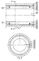
- figure 1 shows a longitudinal section of the outlines of a bearing according to an embodiment of the invention and figure 2 shows a cross section according to II - II in figure 1.
- a gas permeable element 1 in the shape of a cylinder has a surface layer 2 on its envelope surface.
- the element 1 is made of a porous material, e.g. sintered bronze, and the surface layer 2 can be made by mechanical working of the porous material, e.g. by grinding, so that the pore openings are closed completely or partly and the gas permeability of the layer ceases or decreases.
- Member 3 and element 1 are separated by a gap 4.
- a pressure medium in the form of a gas e.g. air, is supplied to the gap 4 via the gas permeable element 3 via a central bore 5 in element 1 and from a source of pressure medium, not shown, in a manner known per se. It is difficult to obtain a proper restriction of the flow in the surface layer 2 by a grinding operation alone. The gas permeability often gets too low or too high, depending on the properties of the porous material and on which grinding procedure is used.
- the surface of the element 1 of the described embodiment of the invention is treated so that the gas permeability is definitely low, e.g. by grinding in a centerless grinding machine and possibly coating with a glue layer, and thereafter a number of holes 6 are taking up in the element.
- the holes are taken up through the surface layer and extend into the porous material a distance corresponding to at least half the diameter of the holes, those portions of the hole walls which are situated inside of said surface layer being limited by a porous material.
- the holes are suitably taken up perpendicular to the surface layer 2, and they can form a number of annular rows around the element 1, so that the gas is introduced through the holes to the gap 4 at desired positions.
- the holes may possibly be arranged in other ways, e.g.
- the holes extend a certain distance into the porous material, the gas flowing through the porous material can flow into the holes comparatively uninterrupted through comparatively large surfaces which enclose the inner portions of the holes. It is important that the holes are taken up in such a way that the surface layers which limit the holes in the porous portion of the element 1 are not closed by the working operation. For this reason it is unsuitable to use conventional drilling methods. Instead a device is used, e.g a so-called laser gun, known per se, by which holes of desired depths can be made by gasification of the worked material without the pores being closed in adjoining portions of the porous part of the element 1.
- a device is used, e.g a so-called laser gun, known per se, by which holes of desired depths can be made by gasification of the worked material without the pores being closed in adjoining portions of the porous part of the element 1.
- the holes are made narrow, between 0,01 and 1 mm in diameter, and arranged so close to each other that an evenly distributed gas flow to the gap 4 is obtained at the same time as the flow through the surface layer is so restricted that a desired stiffness in the bearing is obtained.
- the bottoms of the holes have about semi-spherical shape, and to make sure that the holes have constant cross section areas through the whole surface layer, the holes extend into the porous material a distance corresponding to at least half the diameter of the holes. This also makes the hole wall surface area in the porous material greater than it would be if the holes were extending through the surface layer 2 only, which gives a better and more predictable gas flow.
- a cylinder 1 of sintered bronze may have a length of about 30 mm and an outer diameter of about 20 mm, holes 6 being arranged in rows situated about 6 mm from each end of the cylinder. 16 holes with a diameter of 130 ⁇ m give an air flow through the bearing of 150 l/h from a pressure source with 3 HPa overpressure when the gap 4 is about 18 ⁇ m.
- the cylindrical bearing described above is only one of a number of possible embodiments of the invention, which is also useful in e.g. thrust bearings, and the bearing surface can be flat, conical, spherical or have another shape.
- the porous material is not necessarily metallic, and the less permeable surface layer can be made in other ways than by mechanical working and possibly glueing, e.g. by various chemical methods.
Landscapes
- Engineering & Computer Science (AREA)
- General Engineering & Computer Science (AREA)
- Chemical & Material Sciences (AREA)
- Dispersion Chemistry (AREA)
- Mechanical Engineering (AREA)
- Magnetic Bearings And Hydrostatic Bearings (AREA)
- Sliding-Contact Bearings (AREA)
Description
- The invention relates to a gas bearing of the kind described in the introductory clause of claim 1, and to a method of manufacturing such a bearing.
- A gas bearing substantially as described in the introductory part of claim 1 is known from e.g. US-A-3 169 807. This document shows embodiments wherein a porous element is provided having recesses in the form of dimples, said porous element having, on the non-dimpled portions, some sort of surface layer which can be formed e.g. by coating or impregnating. The densified surface layer can also be formed by applying heat and pressure to the surface so as to densify the non-dimpled portions thereof to a depth less than the depth of the dimples so as not to seal them off. The porous body can be moulded with the dimples formed directly therein and only thereafter the surface layer is being formed in a separate action. This is clearly disadvantageous regarding amongst others the risk to seal the dimples off.
Also as far as manufacturing economy and function is concerned this entails disadvantages. - One purpose of the present invention is to provide a gas bearing of the kind described, in which the holes taken through the surface layer are accurately shaped and their connection to the porous material is such that a good gas permeability is always guaranteed. Another purpose is to provide a method by which a gas bearing according to the first mentioned aspect of the invention can be produced quickly, easily, inexpensively and with a high precision.
- The first mentioned purpose is achieved by giving the gas bearing the characterizing features stated in claim 1. Suitable embodiments are defined in the claims depending on claim 1. The last mentioned purpose is achieved by the method defined in
claim 4. - The following is a detailed description of the invention with reference to the accompanying drawing, in which figure 1 shows a longitudinal section of the outlines of a bearing according to an embodiment of the invention and figure 2 shows a cross section according to II - II in figure 1.
- A gas permeable element 1 in the shape of a cylinder has a surface layer 2 on its envelope surface. The element 1 is made of a porous material, e.g. sintered bronze, and the surface layer 2 can be made by mechanical working of the porous material, e.g. by grinding, so that the pore openings are closed completely or partly and the gas permeability of the layer ceases or decreases.
- A
member 3, e.g. a sleeve, which is rotatable in relation to the element 1, encloses element 1.Member 3 and element 1 are separated by agap 4. A pressure medium in the form of a gas, e.g. air, is supplied to thegap 4 via the gaspermeable element 3 via acentral bore 5 in element 1 and from a source of pressure medium, not shown, in a manner known per se. It is difficult to obtain a proper restriction of the flow in the surface layer 2 by a grinding operation alone. The gas permeability often gets too low or too high, depending on the properties of the porous material and on which grinding procedure is used. For this reason the surface of the element 1 of the described embodiment of the invention is treated so that the gas permeability is definitely low, e.g. by grinding in a centerless grinding machine and possibly coating with a glue layer, and thereafter a number ofholes 6 are taking up in the element. The holes are taken up through the surface layer and extend into the porous material a distance corresponding to at least half the diameter of the holes, those portions of the hole walls which are situated inside of said surface layer being limited by a porous material. The holes are suitably taken up perpendicular to the surface layer 2, and they can form a number of annular rows around the element 1, so that the gas is introduced through the holes to thegap 4 at desired positions. The holes may possibly be arranged in other ways, e.g. as one or more helical rows around the element 1. As the holes extend a certain distance into the porous material, the gas flowing through the porous material can flow into the holes comparatively uninterrupted through comparatively large surfaces which enclose the inner portions of the holes. It is important that the holes are taken up in such a way that the surface layers which limit the holes in the porous portion of the element 1 are not closed by the working operation. For this reason it is unsuitable to use conventional drilling methods. Instead a device is used, e.g a so-called laser gun, known per se, by which holes of desired depths can be made by gasification of the worked material without the pores being closed in adjoining portions of the porous part of the element 1. The holes are made narrow, between 0,01 and 1 mm in diameter, and arranged so close to each other that an evenly distributed gas flow to thegap 4 is obtained at the same time as the flow through the surface layer is so restricted that a desired stiffness in the bearing is obtained. The bottoms of the holes have about semi-spherical shape, and to make sure that the holes have constant cross section areas through the whole surface layer, the holes extend into the porous material a distance corresponding to at least half the diameter of the holes. This also makes the hole wall surface area in the porous material greater than it would be if the holes were extending through the surface layer 2 only, which gives a better and more predictable gas flow. - A cylinder 1 of sintered bronze may have a length of about 30 mm and an outer diameter of about 20 mm,
holes 6 being arranged in rows situated about 6 mm from each end of the cylinder. 16 holes with a diameter of 130 µm give an air flow through the bearing of 150 l/h from a pressure source with 3 HPa overpressure when thegap 4 is about 18 µm. - The cylindrical bearing described above is only one of a number of possible embodiments of the invention, which is also useful in e.g. thrust bearings, and the bearing surface can be flat, conical, spherical or have another shape. The porous material is not necessarily metallic, and the less permeable surface layer can be made in other ways than by mechanical working and possibly glueing, e.g. by various chemical methods.
Claims (6)
- Gas bearing with a bearing surface arranged on a gas permeable element (1) to which a pressure medium can be supplied from an external source and flow through the element (1) to the bearing surface, the element (1) being made of a gas permeable porous material and a less permeable surface layer (2) forming the bearing surface, whereby a number of holes (6) are made which go through the surface layer (2) and into the porous portion of the element (1) so that the portions of the holes (6) which are situated inside the surface layer (2) are limited by the porous material of which the pores are not closed characterized in that said holes (6) have a diameter of between 0,01 and 1 mm and extend into the porous material a distance corresponding to at least half of the said diameter.
- Gas bearing according to claim 1 or 2, in which the bearing surface is cylindrical and arranged on the exterior around an element (1) of a porous material.
- Gas bearing according to any one of claims 1 - 3, in which the surface layer (2) is a portion of the element which is mechanically worked.
- Method of producing a gas bearing according to claim 1 characterized in that the holes (6) in the surface layer (2) and extending into the porous material of element (1) are produced by gasification of the material.
- Method according to claim 4 by which the surface layer is produced by working the surface of the element mechanically.
- Method according to claim 4 or 5, by which the gasification is made by a laser gun.
Applications Claiming Priority (2)
| Application Number | Priority Date | Filing Date | Title |
|---|---|---|---|
| SE8601258A SE448252B (en) | 1986-03-18 | 1986-03-18 | GAS STORAGE WITH A STORAGE AREA ORGANIZED ON A GAS TRANSFERABLE ELEMENT AS WELL AS TO MAKE A SUCH STOCK |
| SE8601258 | 1986-03-18 |
Publications (3)
| Publication Number | Publication Date |
|---|---|
| EP0237627A2 EP0237627A2 (en) | 1987-09-23 |
| EP0237627A3 EP0237627A3 (en) | 1988-08-03 |
| EP0237627B1 true EP0237627B1 (en) | 1992-03-18 |
Family
ID=20363876
Family Applications (1)
| Application Number | Title | Priority Date | Filing Date |
|---|---|---|---|
| EP86116098A Expired - Lifetime EP0237627B1 (en) | 1986-03-18 | 1986-11-20 | Gas bearing and method of making it |
Country Status (5)
| Country | Link |
|---|---|
| US (1) | US4744676A (en) |
| EP (1) | EP0237627B1 (en) |
| JP (1) | JPS62220716A (en) |
| DE (1) | DE3684458D1 (en) |
| SE (1) | SE448252B (en) |
Families Citing this family (21)
| Publication number | Priority date | Publication date | Assignee | Title |
|---|---|---|---|---|
| EP0297164B1 (en) * | 1987-06-29 | 1992-04-08 | Nippon Telegraph And Telephone Corporation | Porous static pressure guide |
| DE4403340A1 (en) * | 1994-02-03 | 1995-08-10 | Heinzl Joachim | Method for producing at least one micro nozzle of an aerostatic bearing |
| DE4436156C1 (en) | 1994-10-10 | 1996-03-21 | Heinzl Joachim | Aerostatic bearing and method for manufacturing an aerostatic bearing |
| DE19630477A1 (en) * | 1996-07-27 | 1998-01-29 | Rieter Ingolstadt Spinnerei | Open-end spinning device |
| DE19630476A1 (en) * | 1996-07-27 | 1998-01-29 | Rieter Ingolstadt Spinnerei | Open-end spinning device |
| US20040155534A1 (en) * | 2003-02-07 | 2004-08-12 | Engwall Mats Anders | Structure integrating gas support bearing and a planar electromagnetic drive and levitation system |
| DE102004048944A1 (en) * | 2004-10-07 | 2006-04-20 | Aerolas Gmbh, Aerostatische Lager- Lasertechnik | Gas bearing arrangement of relatively movable bodies |
| SE526359C2 (en) * | 2005-01-13 | 2005-08-30 | Lind Finance & Dev Ab | Gas bearing production method, comprises forming first set of holes in bearing surface, measuring gas flow and forming more holes so that desired gas flow is obtained |
| US7429132B1 (en) * | 2005-08-16 | 2008-09-30 | Florida Turbine Technologies, Inc. | Hydrostatic air bearing with a porous metal ring |
| CN103016529B (en) * | 2012-12-31 | 2015-02-18 | 浙江工业大学 | Air floatation combination device not affected by air pipe disturbance and high-pressure gas |
| US11097974B2 (en) | 2014-07-31 | 2021-08-24 | Corning Incorporated | Thermally strengthened consumer electronic glass and related systems and methods |
| EP3174835B1 (en) * | 2014-07-31 | 2025-09-10 | Corning Incorporated | Methods for thermal tempering of glass |
| US10611664B2 (en) | 2014-07-31 | 2020-04-07 | Corning Incorporated | Thermally strengthened architectural glass and related systems and methods |
| US12338159B2 (en) | 2015-07-30 | 2025-06-24 | Corning Incorporated | Thermally strengthened consumer electronic glass and related systems and methods |
| KR101952085B1 (en) | 2016-01-12 | 2019-05-21 | 코닝 인코포레이티드 | Thin, thermally and chemically tempered glass-based products |
| US11795102B2 (en) | 2016-01-26 | 2023-10-24 | Corning Incorporated | Non-contact coated glass and related coating system and method |
| TW201920028A (en) | 2017-08-24 | 2019-06-01 | 美商康寧公司 | Glasses with improved tempering capabilities |
| TWI785156B (en) | 2017-11-30 | 2022-12-01 | 美商康寧公司 | Non-iox glasses with high coefficient of thermal expansion and preferential fracture behavior for thermal tempering |
| CN113727954A (en) | 2019-04-23 | 2021-11-30 | 康宁股份有限公司 | Glass laminates having defined stress profiles and methods of making same |
| CN114514115B (en) | 2019-08-06 | 2023-09-01 | 康宁股份有限公司 | Glass laminate with embedded stress spike for crack prevention and method of making same |
| DE112020005994T5 (en) | 2019-12-07 | 2022-10-13 | Akribis Systems Pte Ltd | Ultra low profile aerostatic bearing and method of making same |
Family Cites Families (9)
| Publication number | Priority date | Publication date | Assignee | Title |
|---|---|---|---|---|
| US3169807A (en) * | 1962-06-28 | 1965-02-16 | Tann Corp | Air bearing |
| US3527510A (en) * | 1968-12-05 | 1970-09-08 | Gen Motors Corp | Antihammer device for air spindles |
| US3620581A (en) * | 1970-10-12 | 1971-11-16 | Us Air Force | Porous hydrostatic bearing |
| US3645589A (en) * | 1970-12-03 | 1972-02-29 | Gen Motors Corp | Air bearing with low tensile strength permeable sleeve |
| JPS5731004B2 (en) * | 1973-04-14 | 1982-07-02 | ||
| US4030784A (en) * | 1976-06-18 | 1977-06-21 | General Motors Corporation | Gas bearing roll shell assembly with selective drive means |
| JPS571170U (en) * | 1980-06-02 | 1982-01-06 | ||
| DE3110712C2 (en) * | 1981-03-19 | 1986-08-07 | Joachim Prof. Dr.-Ing. 8000 München Heinzl | Aerostatic bearing |
| DE3230232A1 (en) * | 1982-08-13 | 1984-02-16 | Interatom Internationale Atomreaktorbau Gmbh, 5060 Bergisch Gladbach | Bearing shell for a hydrostatic gas bearing and a method for its production |
-
1986
- 1986-03-18 SE SE8601258A patent/SE448252B/en not_active IP Right Cessation
- 1986-11-20 EP EP86116098A patent/EP0237627B1/en not_active Expired - Lifetime
- 1986-11-20 DE DE8686116098T patent/DE3684458D1/en not_active Expired - Lifetime
- 1986-12-29 US US06/946,829 patent/US4744676A/en not_active Expired - Fee Related
-
1987
- 1987-03-16 JP JP62059097A patent/JPS62220716A/en active Pending
Also Published As
| Publication number | Publication date |
|---|---|
| SE448252B (en) | 1987-02-02 |
| EP0237627A3 (en) | 1988-08-03 |
| EP0237627A2 (en) | 1987-09-23 |
| US4744676A (en) | 1988-05-17 |
| DE3684458D1 (en) | 1992-04-23 |
| JPS62220716A (en) | 1987-09-28 |
| SE8601258D0 (en) | 1986-03-18 |
Similar Documents
| Publication | Publication Date | Title |
|---|---|---|
| US4744676A (en) | Gas bearing and method of making it | |
| US4274479A (en) | Sintered grooved wicks | |
| AU609123B2 (en) | Improved bearing structure for downhole motors | |
| US3978176A (en) | Sparger | |
| US3169807A (en) | Air bearing | |
| JP3860253B2 (en) | Static pressure gas bearing | |
| US4541739A (en) | Controlled capillary ball bearing cage | |
| JPH0249825B2 (en) | ||
| CN101535666A (en) | Gas thrust bearing and bearing bush thereof | |
| JPS61286611A (en) | Gas static pressure bearing | |
| US6361737B1 (en) | Method for producing a sintered porous bearing and the sintered porous bearing | |
| KR890014207A (en) | Manufacturing method of cutting tools such as drill and end mill | |
| GB2082290A (en) | Valves particularly servovalves | |
| US5559852A (en) | Rotary-anode X-ray tube comprising a sleeve bearing | |
| JPS6442374A (en) | Oil-impregnated porous ceramic ball | |
| US3719405A (en) | Gas bearing | |
| JP4442012B2 (en) | Porous static pressure gas bearing and manufacturing method thereof | |
| EP3620693A1 (en) | Tribological body and method for manufacturing same | |
| JPH04262116A (en) | hybrid bearing | |
| JPH0558850B2 (en) | ||
| US4972751A (en) | Rotary valves for brass wind instruments | |
| JP3620814B2 (en) | Porous composite bearing | |
| JP4461593B2 (en) | Method for producing porous hydrostatic gas bearing | |
| JPS5648213A (en) | Ultrafiltration element and its production | |
| US20040069050A1 (en) | Rheometer |
Legal Events
| Date | Code | Title | Description |
|---|---|---|---|
| PUAI | Public reference made under article 153(3) epc to a published international application that has entered the european phase |
Free format text: ORIGINAL CODE: 0009012 |
|
| AK | Designated contracting states |
Kind code of ref document: A2 Designated state(s): CH DE FR GB IT LI |
|
| PUAL | Search report despatched |
Free format text: ORIGINAL CODE: 0009013 |
|
| AK | Designated contracting states |
Kind code of ref document: A3 Designated state(s): CH DE FR GB IT LI |
|
| 17P | Request for examination filed |
Effective date: 19890522 |
|
| 17Q | First examination report despatched |
Effective date: 19900831 |
|
| GRAA | (expected) grant |
Free format text: ORIGINAL CODE: 0009210 |
|
| AK | Designated contracting states |
Kind code of ref document: B1 Designated state(s): CH DE FR GB IT LI |
|
| REF | Corresponds to: |
Ref document number: 3684458 Country of ref document: DE Date of ref document: 19920423 |
|
| ET | Fr: translation filed | ||
| ITF | It: translation for a ep patent filed | ||
| PGFP | Annual fee paid to national office [announced via postgrant information from national office to epo] |
Ref country code: GB Payment date: 19921106 Year of fee payment: 7 |
|
| PGFP | Annual fee paid to national office [announced via postgrant information from national office to epo] |
Ref country code: FR Payment date: 19921109 Year of fee payment: 7 |
|
| PGFP | Annual fee paid to national office [announced via postgrant information from national office to epo] |
Ref country code: CH Payment date: 19921125 Year of fee payment: 7 |
|
| PGFP | Annual fee paid to national office [announced via postgrant information from national office to epo] |
Ref country code: DE Payment date: 19921212 Year of fee payment: 7 |
|
| PLBE | No opposition filed within time limit |
Free format text: ORIGINAL CODE: 0009261 |
|
| STAA | Information on the status of an ep patent application or granted ep patent |
Free format text: STATUS: NO OPPOSITION FILED WITHIN TIME LIMIT |
|
| 26N | No opposition filed | ||
| PG25 | Lapsed in a contracting state [announced via postgrant information from national office to epo] |
Ref country code: GB Effective date: 19931120 |
|
| PG25 | Lapsed in a contracting state [announced via postgrant information from national office to epo] |
Ref country code: LI Effective date: 19931130 Ref country code: CH Effective date: 19931130 |
|
| GBPC | Gb: european patent ceased through non-payment of renewal fee |
Effective date: 19931120 |
|
| PG25 | Lapsed in a contracting state [announced via postgrant information from national office to epo] |
Ref country code: FR Effective date: 19940729 |
|
| REG | Reference to a national code |
Ref country code: CH Ref legal event code: PL |
|
| PG25 | Lapsed in a contracting state [announced via postgrant information from national office to epo] |
Ref country code: DE Effective date: 19940802 |
|
| REG | Reference to a national code |
Ref country code: FR Ref legal event code: ST |
|
| PG25 | Lapsed in a contracting state [announced via postgrant information from national office to epo] |
Ref country code: IT Free format text: LAPSE BECAUSE OF NON-PAYMENT OF DUE FEES;WARNING: LAPSES OF ITALIAN PATENTS WITH EFFECTIVE DATE BEFORE 2007 MAY HAVE OCCURRED AT ANY TIME BEFORE 2007. THE CORRECT EFFECTIVE DATE MAY BE DIFFERENT FROM THE ONE RECORDED. Effective date: 20051120 |