EP0237549B1 - Flux diverting flow chamber for high gradient magnetic separation of particles from a liquid medium - Google Patents
Flux diverting flow chamber for high gradient magnetic separation of particles from a liquid medium Download PDFInfo
- Publication number
- EP0237549B1 EP0237549B1 EP86905637A EP86905637A EP0237549B1 EP 0237549 B1 EP0237549 B1 EP 0237549B1 EP 86905637 A EP86905637 A EP 86905637A EP 86905637 A EP86905637 A EP 86905637A EP 0237549 B1 EP0237549 B1 EP 0237549B1
- Authority
- EP
- European Patent Office
- Prior art keywords
- poles
- matrix
- chamber
- magnetizing means
- respect
- Prior art date
- Legal status (The legal status is an assumption and is not a legal conclusion. Google has not performed a legal analysis and makes no representation as to the accuracy of the status listed.)
- Expired
Links
- 230000004907 flux Effects 0.000 title claims abstract description 48
- 239000002245 particle Substances 0.000 title abstract description 55
- 238000007885 magnetic separation Methods 0.000 title abstract description 10
- 239000007788 liquid Substances 0.000 title description 2
- 239000011159 matrix material Substances 0.000 claims abstract description 101
- 230000005291 magnetic effect Effects 0.000 claims abstract description 78
- 239000012530 fluid Substances 0.000 claims abstract description 54
- 238000000926 separation method Methods 0.000 claims abstract description 20
- 230000008878 coupling Effects 0.000 claims abstract description 9
- 238000010168 coupling process Methods 0.000 claims abstract description 9
- 238000005859 coupling reaction Methods 0.000 claims abstract description 9
- 239000006249 magnetic particle Substances 0.000 claims abstract description 4
- 230000035699 permeability Effects 0.000 claims description 12
- 210000004027 cell Anatomy 0.000 abstract description 19
- 210000000601 blood cell Anatomy 0.000 abstract description 4
- 239000006148 magnetic separator Substances 0.000 abstract description 2
- 230000000717 retained effect Effects 0.000 abstract description 2
- 230000009977 dual effect Effects 0.000 description 8
- 210000003743 erythrocyte Anatomy 0.000 description 6
- 230000005415 magnetization Effects 0.000 description 6
- 238000000034 method Methods 0.000 description 5
- 210000004369 blood Anatomy 0.000 description 4
- 238000001914 filtration Methods 0.000 description 4
- 238000011010 flushing procedure Methods 0.000 description 4
- 239000000463 material Substances 0.000 description 4
- 230000009467 reduction Effects 0.000 description 4
- 239000008280 blood Substances 0.000 description 3
- 239000000835 fiber Substances 0.000 description 3
- 239000012634 fragment Substances 0.000 description 3
- 229910001209 Low-carbon steel Inorganic materials 0.000 description 2
- FAPWRFPIFSIZLT-UHFFFAOYSA-M Sodium chloride Chemical compound [Na+].[Cl-] FAPWRFPIFSIZLT-UHFFFAOYSA-M 0.000 description 2
- 230000001413 cellular effect Effects 0.000 description 2
- 230000007423 decrease Effects 0.000 description 2
- 238000013467 fragmentation Methods 0.000 description 2
- 238000006062 fragmentation reaction Methods 0.000 description 2
- 230000014759 maintenance of location Effects 0.000 description 2
- 230000008569 process Effects 0.000 description 2
- 230000004044 response Effects 0.000 description 2
- 238000005070 sampling Methods 0.000 description 2
- 229910001220 stainless steel Inorganic materials 0.000 description 2
- 239000010935 stainless steel Substances 0.000 description 2
- 230000009471 action Effects 0.000 description 1
- 239000012190 activator Substances 0.000 description 1
- 239000003153 chemical reaction reagent Substances 0.000 description 1
- 239000003638 chemical reducing agent Substances 0.000 description 1
- 238000004891 communication Methods 0.000 description 1
- 150000001875 compounds Chemical class 0.000 description 1
- 230000003247 decreasing effect Effects 0.000 description 1
- 230000005292 diamagnetic effect Effects 0.000 description 1
- GRWZHXKQBITJKP-UHFFFAOYSA-L dithionite(2-) Chemical compound [O-]S(=O)S([O-])=O GRWZHXKQBITJKP-UHFFFAOYSA-L 0.000 description 1
- 230000000694 effects Effects 0.000 description 1
- 230000008030 elimination Effects 0.000 description 1
- 238000003379 elimination reaction Methods 0.000 description 1
- 238000004146 energy storage Methods 0.000 description 1
- 230000005284 excitation Effects 0.000 description 1
- 229910052500 inorganic mineral Inorganic materials 0.000 description 1
- 239000010954 inorganic particle Substances 0.000 description 1
- UQSXHKLRYXJYBZ-UHFFFAOYSA-N iron oxide Inorganic materials [Fe]=O UQSXHKLRYXJYBZ-UHFFFAOYSA-N 0.000 description 1
- 235000013980 iron oxide Nutrition 0.000 description 1
- VBMVTYDPPZVILR-UHFFFAOYSA-N iron(2+);oxygen(2-) Chemical class [O-2].[Fe+2] VBMVTYDPPZVILR-UHFFFAOYSA-N 0.000 description 1
- 230000005389 magnetism Effects 0.000 description 1
- 239000012528 membrane Substances 0.000 description 1
- 239000011707 mineral Substances 0.000 description 1
- 230000010355 oscillation Effects 0.000 description 1
- 239000007800 oxidant agent Substances 0.000 description 1
- 230000001590 oxidative effect Effects 0.000 description 1
- 230000005298 paramagnetic effect Effects 0.000 description 1
- 230000000737 periodic effect Effects 0.000 description 1
- 230000010399 physical interaction Effects 0.000 description 1
- 238000011045 prefiltration Methods 0.000 description 1
- 230000001902 propagating effect Effects 0.000 description 1
- 239000002002 slurry Substances 0.000 description 1
- 239000011343 solid material Substances 0.000 description 1
- 125000006850 spacer group Chemical group 0.000 description 1
- 238000004804 winding Methods 0.000 description 1
Images




Classifications
-
- B—PERFORMING OPERATIONS; TRANSPORTING
- B03—SEPARATION OF SOLID MATERIALS USING LIQUIDS OR USING PNEUMATIC TABLES OR JIGS; MAGNETIC OR ELECTROSTATIC SEPARATION OF SOLID MATERIALS FROM SOLID MATERIALS OR FLUIDS; SEPARATION BY HIGH-VOLTAGE ELECTRIC FIELDS
- B03C—MAGNETIC OR ELECTROSTATIC SEPARATION OF SOLID MATERIALS FROM SOLID MATERIALS OR FLUIDS; SEPARATION BY HIGH-VOLTAGE ELECTRIC FIELDS
- B03C1/00—Magnetic separation
- B03C1/02—Magnetic separation acting directly on the substance being separated
- B03C1/025—High gradient magnetic separators
- B03C1/031—Component parts; Auxiliary operations
- B03C1/033—Component parts; Auxiliary operations characterised by the magnetic circuit
-
- B—PERFORMING OPERATIONS; TRANSPORTING
- B03—SEPARATION OF SOLID MATERIALS USING LIQUIDS OR USING PNEUMATIC TABLES OR JIGS; MAGNETIC OR ELECTROSTATIC SEPARATION OF SOLID MATERIALS FROM SOLID MATERIALS OR FLUIDS; SEPARATION BY HIGH-VOLTAGE ELECTRIC FIELDS
- B03C—MAGNETIC OR ELECTROSTATIC SEPARATION OF SOLID MATERIALS FROM SOLID MATERIALS OR FLUIDS; SEPARATION BY HIGH-VOLTAGE ELECTRIC FIELDS
- B03C1/00—Magnetic separation
- B03C1/02—Magnetic separation acting directly on the substance being separated
- B03C1/025—High gradient magnetic separators
- B03C1/031—Component parts; Auxiliary operations
- B03C1/032—Matrix cleaning systems
-
- B—PERFORMING OPERATIONS; TRANSPORTING
- B03—SEPARATION OF SOLID MATERIALS USING LIQUIDS OR USING PNEUMATIC TABLES OR JIGS; MAGNETIC OR ELECTROSTATIC SEPARATION OF SOLID MATERIALS FROM SOLID MATERIALS OR FLUIDS; SEPARATION BY HIGH-VOLTAGE ELECTRIC FIELDS
- B03C—MAGNETIC OR ELECTROSTATIC SEPARATION OF SOLID MATERIALS FROM SOLID MATERIALS OR FLUIDS; SEPARATION BY HIGH-VOLTAGE ELECTRIC FIELDS
- B03C1/00—Magnetic separation
- B03C1/02—Magnetic separation acting directly on the substance being separated
- B03C1/025—High gradient magnetic separators
- B03C1/031—Component parts; Auxiliary operations
- B03C1/033—Component parts; Auxiliary operations characterised by the magnetic circuit
- B03C1/0332—Component parts; Auxiliary operations characterised by the magnetic circuit using permanent magnets
-
- B—PERFORMING OPERATIONS; TRANSPORTING
- B03—SEPARATION OF SOLID MATERIALS USING LIQUIDS OR USING PNEUMATIC TABLES OR JIGS; MAGNETIC OR ELECTROSTATIC SEPARATION OF SOLID MATERIALS FROM SOLID MATERIALS OR FLUIDS; SEPARATION BY HIGH-VOLTAGE ELECTRIC FIELDS
- B03C—MAGNETIC OR ELECTROSTATIC SEPARATION OF SOLID MATERIALS FROM SOLID MATERIALS OR FLUIDS; SEPARATION BY HIGH-VOLTAGE ELECTRIC FIELDS
- B03C1/00—Magnetic separation
- B03C1/02—Magnetic separation acting directly on the substance being separated
- B03C1/025—High gradient magnetic separators
- B03C1/031—Component parts; Auxiliary operations
- B03C1/033—Component parts; Auxiliary operations characterised by the magnetic circuit
- B03C1/034—Component parts; Auxiliary operations characterised by the magnetic circuit characterised by the matrix elements
-
- B—PERFORMING OPERATIONS; TRANSPORTING
- B03—SEPARATION OF SOLID MATERIALS USING LIQUIDS OR USING PNEUMATIC TABLES OR JIGS; MAGNETIC OR ELECTROSTATIC SEPARATION OF SOLID MATERIALS FROM SOLID MATERIALS OR FLUIDS; SEPARATION BY HIGH-VOLTAGE ELECTRIC FIELDS
- B03C—MAGNETIC OR ELECTROSTATIC SEPARATION OF SOLID MATERIALS FROM SOLID MATERIALS OR FLUIDS; SEPARATION BY HIGH-VOLTAGE ELECTRIC FIELDS
- B03C1/00—Magnetic separation
- B03C1/02—Magnetic separation acting directly on the substance being separated
- B03C1/28—Magnetic plugs and dipsticks
- B03C1/288—Magnetic plugs and dipsticks disposed at the outer circumference of a recipient
-
- B—PERFORMING OPERATIONS; TRANSPORTING
- B03—SEPARATION OF SOLID MATERIALS USING LIQUIDS OR USING PNEUMATIC TABLES OR JIGS; MAGNETIC OR ELECTROSTATIC SEPARATION OF SOLID MATERIALS FROM SOLID MATERIALS OR FLUIDS; SEPARATION BY HIGH-VOLTAGE ELECTRIC FIELDS
- B03C—MAGNETIC OR ELECTROSTATIC SEPARATION OF SOLID MATERIALS FROM SOLID MATERIALS OR FLUIDS; SEPARATION BY HIGH-VOLTAGE ELECTRIC FIELDS
- B03C2201/00—Details of magnetic or electrostatic separation
- B03C2201/18—Magnetic separation whereby the particles are suspended in a liquid
Definitions
- the present invention is in the field of instrumentation and more particularly relates to apparatus for magnetically separating particles from a liquid medium.
- HGMS high-gradient magnetic separation
- HGMS HGMS systems
- the collection of particles occurs on a matrix of magnetic wires, fibers, spheres or other high permeability members situated in a magnetic flux.
- matrices are characterized by interstitial spaces through which the particles and carrier fluid may pass.
- each particle experiences a magnetic force toward the matrix elements proportional to ( ⁇ p - ⁇ f ) V p H dH/dx, where ⁇ p is the susceptibility of the particle, ⁇ f is the susceptibility of the carrier fluid, V p is the volume of the particle, H is the magnetic field intensity and x is a spatial dimension away from the matrix surface.
- ⁇ p exceeds ⁇ f , that is where the particles are more "magnetic” than the carrier fluid
- the particles are attracted to the elements of the matrix in the "strong field” regions at those elements.
- ⁇ f exceeds ⁇ p , that is, where the carrier fluid is more "magnetic” than the particles
- the particles are repelled from the strong field regions, but may be attracted to the weak or low field regions, at the matrix elements.
- a fluid carrying the particles-to-be-separated is passed through the matrix at flow rates sufficiently low that magnetic attractive forces on the particles in the matrix exceed viscous and gravitational forces. As a consequence, those particles are held, or captured, against portions of the matrix while the carrier fluid exits the matrix.
- An elutriation phase may then be initiated to retrieve the captured particles from the matrix, for example, for subsequent analysis.
- HGMS systems where the magnetic flux is generated by an electromagnet, or by a permanent magnet whose flux is by some means removed from the matrix during the elutriation phase, particles can be released from the matrix following their collection from the particle-laden carrier by first interrupting drive current to the winding of the electromagnet, or removing the permanent magnet flux from the matrix. However, residual magnetism in the system may cause some particles to be held by the matrix. Then the velocity at which the elutriation fluid is driven through the matrix may be selectively increased to remove the non-released particles from the matrix.
- HGMS systems where the magnetic flux is generated by permanent magnets, and the matrix is maintained within the magnetic flux path at all times, that flux may continue to cause retention of the captured particles even upon the introduction of an elutriation fluid.
- the common method for elutriating the captured particles in this case is to appreciably increase fluid flow rates, so that the viscous drag forces exceed the magnetic retention forces; the captured particles are thus flushed off the matrix.
- This latter approach has been widely used with inorganic particles, but has been less successful when applied to separation of fragile particles such as intact living biological cells.
- Cellular debris observed in the flush effluent particularly when old bloods are subjected to this method of cell elutriation, demonstrate that the method is too harsh for use with many clinical specimens.
- DE-A-3,314,923 discloses a separator apparatus for separating magnetic particles from a fluid medium, wherein the apparatus comprises a rotatable magnet to magnetise and demagnetise the surrounding matrix.
- Another object is to provide an improved apparatus for magnetically capturing, and providing the intact removal therefrom of, fragile particles in a fluid medium.
- Yet another object is to provide an improved apparatus for magnetically capturing, and providing the removal therefrom of, intact biological cells from a fluid medium.
- separator apparatus for separating magnetic particles from a fluid medium, comprising a separator including a housing defining a flow chamber having at least one input port and at least one output port and extending along a reference axis, said chamber defining a fluid flow path therethrough from one of said input ports to one of said output ports, a high magnetic permeability, interstitial separation matrix positioned within said flow chamber whereby fluid flowing between said input and output ports passes substantially through interstices in said matrix, a magnetizing means for selectively coupling magnetic flux to said matrix, wherein the said magnetizing means includes two opposite polarity magnet poles positioned external to the flow chamber and on opposite sides of said reference axis and wherein the flow chamber includes within the said housing relatively high magnetic permeability elements external to the said matrix, the said elements including means for establishing a flux path between the poles of said magnetizing means in each of a first position and a second position at said chamber, and the flow chamber is selectively rotatable about the said reference axis between the
- the invention is directed to the magnetic separation of fragile particles, such as intact biological cells, from a fluid medium.
- the invention provides a high gradient magnetic separation (HGMS) system having both a flow chamber housing an interstitial separation matrix and associated magnetizing apparatus for coupling magnetic flux to the matrix.
- the interstitial matrix includes high magnetic permeability wires, fibers, spheres or the like and has interstices through which a carrier fluid carrying the cells-to-be-separated may be passed.
- the magnetizing apparatus includes a permanent magnet having opposing North and South poles and field-guiding pole pieces, external to the flow chamber.
- the flow chamber comprises a dual-position flux-coupler. The flux-coupler is operative in a first position in the capture phase and in a second position in an elutriation phase.
- the flux-coupler is positioned to permit the magnetic flux from one magnetic pole to pass through the matrix to the other magnetic pole.
- input fluid particles for which the magnetic attractive forces exceed viscous and gravitational forces are retained in the matrix.
- the flux-coupler In the elutriation phase, the flux-coupler is positioned so that magnetic flux is diverted away from the matrix. In this phase, the appreciable reduction or elimination of magnetic flux from the matrix permits viscous forces of the fluid to remove the captured particles from the matrix at low flow velocities.
- a HGMS system of the type taught by the invention is capable of non-destructively separating fragile particles, e.g., intact blood cells, from a carrier fluid.
- an acoustic removal apparatus is incorporated into the flux diverting flow chamber to aid in dislodging captured particles from the matrix in the elutriation phase.
- the acoustical removal apparatus includes a piezoelectric transducer, which is acoustically coupled to the matrix, and an associated drive circuit.
- the piezoelectric transducer may be affixed to a wall of the chamber housing the matrix with the transducer being in fluid communication with the matrix.
- the piezoelectric transducer may be mechanically coupled to the matrix.
- the HGMS system may operate with the flux coupler in its first position and otherwise operate in a conventional manner in the capture phase, whereby fragile particles are selectively captured magnetically from a carrier fluid passing through the matrix, with those captured particles being held in place within the matrix.
- an elutriation fluid is passed through the matrix.
- the drive circuit excites the piezoelectric transducer.
- the transducer establishes acoustic waves in the elutriation fluid passing through the matrix, vibrating the matrix itself.
- the acoustic waves may be ultrasonic. The acoustic waves and matrix vibration operate to dislodge the intact cells from the matrix, permitting even lower elutriation flow rates than may be necessary using the flux-diverting features of the invention alone.
- a single separator can be used, or alternatively, pairs of mechanically coupled separators can be arranged in dual separator configurations.
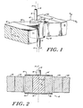
- Figs. 1-5 show a separator 10 for a high-gradient magnetic separation (HGMS) system.
- the separator 10 of the present embodiment is disclosed with a permanent magnet for generating the magnetic field used in particle separation.
- the invention is also applicable to an electromagnet-based HGMS system, where the separation magnetic field is generated with an electromagnet and the removal of captured particles may be achieved either with the magnet energized or de-energized.
- the separator 10 includes a generally cylindrical flow chamber 12 extending along a reference axis 13 and having an input port 14 and an end member 14' and an output port 16 and an end member 16'. In other forms of the invention, additional input and output ports can also be provided for flow chamber 12. In the presently described embodiment, the axis 13 is aligned with the local vertical.
- the chamber 12 is adapted to permit fluid flow from the port 14 to the port 16 generally along the flow axis 17.
- a permanent magnet assembly is exterior to the chamber 12.
- the magnet assembly includes a North pole 18 and associated high permeability field-converging pole piece 20 and a South pole 22 and associated high permeability field-converging pole piece 24.
- the pole pieces 20 and 24, together with the flow chamber 12, establish a flux path between the poles 18 and 22.
- the poles 18 and 22 may be provided by a single "horseshoe", or C-shaped, magnet.
- electromagnet embodiments conventional-type electromagnets and energizing circuits, not shown, may be used.
- a reference line 26 is shown on the end piece 16' which passes through axis 13 and axis 17. That reference line 26 is indicative in the Figures of the angular orientation of the chamber 12 about axis 13.
- the chamber 12 includes a high permeability, interstitial separation matrix 30.
- the matrix 30 is positioned along the axis 17 within the flow chamber 12 in a manner such that fluid driven between the ports 14 and 16 passes substantially through the matrix 30.
- the matrix 30 is a high permeability assembly constructed of magnetic wires, fibers, spheres, or the like, in a conventional fashion, having interstices large enough to permit the carrier fluid and particles to flow therethrough.
- the matrix elements may be 5-15% of the chamber's interior volume.
- the flow axis 17 is offset with respect to the reference axis 13, which in this embodiment is aligned with the local vertical.
- the flow axis 17 may be offset from the vertical at any angle in the range zero to ninety degrees.
- the offset of the axis 17 is substantially equal to forty-five degrees, although other orientations may be used.
- the fluid flow through the chamber 12 includes a directed component opposite to the local gravitational field. As a result, the gravitational field assists the separation process by causing a relative slowing of the particle flow in the carrier fluid.
- the chamber 12 is formed from cylindrical section sidewall members 40 and 42, which are non-magnetic, i.e. having low magnetic permeability, and cylindrical section sidewall members 44 and 46, which are magnetic.
- the outer surface of the members 40, 42, 44 and 46 form a cylindrical surface coaxial with the reference axis 13.
- the entire flow chamber 12 is selectively rotatable about the axis 13 so that in a first position as shown in Figs. 1, 2 and 4, a flux path is established from the pole 18 through the pole piece 20, sidewall member 44, matrix 30, sidewall member 46, and pole piece 24 to the pole 22.
- a second position of the chamber 12 where the chamber 12 is offset by ninety degrees with respect to the first position, as shown in Figs.
- a low-reluctance flux path is established from the pole 18 through the pole piece 20, through both sidewall members 44 and 46, and the pole piece 24 to the pole 22, so that the flux substantially by-passes the matrix 30.
- the principal flux paths for the two positions of the chamber 12 are indicated by the arrows in Figs. 4 and 5, respectively.
- the reluctance of the principal flux path illustrated in Fig. 4 is relatively high compared to that of the principal flux path illustrated in Fig. 5.
- a piezoelectric plate 52 is mounted in or on one wall (e.g. wall 40) of the chamber 12.
- the plate 52 is coupled to a drive network 53.
- a back-loading element 54 may be used for quarter-wave impedance matching of the load to the piezoelectric plate 52, as is known in the art of ultrasonic transducers.
- the plate 52 is mounted on, but electrically insulated from, the sidewall 40 of the chamber 12 and is in mechanical contact with the matrix 30.
- the plate 52 may be spaced apart from (but in fluidic coupling with) the matrix 30.
- the plate 52 may be exposed to the fluid containing the particles to be separated, or isolated from it by a thin membrane, insulating film or the like.
- the preferred embodiment is particularly adapted to remove intact biological cells (such as erythrocytes) from a fluid medium (such as whole blood).
- a fluid driver, or pump is adapted to drive the fluid medium through the chamber 12 in the capture phase of operation.
- the chamber 12 is in the position shown in Figs. 1, 2 and 4, the plate 52 is passive, and the magnetic field passes through the matrix 30.
- the cells passing in close proximity to the matrix elements are held, or captured, by those elements due to the forces generated on these particles by the magnetic field, as in conventional HGMS system operation.
- an elutriation fluid may be substituted for the feed fluid and the elutriation phase begun.
- the chamber 12 is in the position shown in Figs. 3 and 5 whereby the magnetic field is shunted through the sidewalls 44 and 46, that is, around the matrix 30.
- Relatively low flow rates compared to that required by the prior art, suffice to flush the captured particles from the matrix 30, even in the continuing presence of the magnetizing field.
- the drive network 53 drives the plate 52 to generate a high frequency, e.g. 15 KHz, acoustic wave through the fluid in chamber 12.
- the drive waveform generated by network 53 may be a pulse or pulse train, for example, from an energy storage circuit.
- the drive waveform may be a periodic oscillation gated off after the captured particles are elutriated, or another suitable waveform.
- acoustic waves set up by the plate in response to the drive dislodge the particles from the matrix, either by driving the matrix 30 mechanically, or by the action of the acoustic waves propagating through the chamber volume.
- the captured particles may be removed with lower flow rates than may be permitted by flux diversion alone.
- the reduction in flow rates during elutriation depends on the strength of the acoustic wave and is more effective with back-loading established by element 54 on the outer surface of the plate 52.
- the magnet poles 18 and 22, the pole pieces 20 and 24 and the flow chamber 12 form a magnetic switch, which by the mechanical rotation of the flow chamber 12 about the axis 13 diverts the magnetizing flux around the matrix 30 during the elutriation phase.
- the matrix 30 is shown to be in direct contact with structural elements of the chamber 12, the matrix may alternatively be contained in a suitable, even disposable, cartridge which may be inserted into the rotatable structure of the chamber 12.
- the pole pieces 20 and 24 and sidewall members 44 and 46 may be mild steel. Alternatively, other high saturation materials may be used. If corrosive carrier fluids are allowed to contact the sidewalls 44 and 46, these elements may be magnetic stainless steel.
- the magnetic segments 44 and 46 When the chamber 12 is in its second position, i.e. during elutriation, the magnetic segments 44 and 46 effectively shunt the magnet gap, diverting the magnetization flux through themselves. If the minimum cross-sectional area of the segment/pole-piece configuration is greater than the saturation area for the segment material at the chosen magnetizing field strength, the residual flux through the matrix 30 is greatly reduced compared to the levels present during the capture phase. The captured particles may then be elutriated with correspondingly reduced fluid velocities, and the chamber may be returned to its capture position for introduction of further feed fluid.
- the sample may be diluted by providing a sampling chamber in one of the cylindrical segments (such as segment 44 or 46) which is filled during the elutriation phase of the previous cycle. During the next capture phase, this sampling chamber is flushed into the chamber housing matrix 30.
- the flushing may be accomplished with a suitable fluid, such as isotonic saline containing a reductant or oxidant, in one type of blood-cell separation.
- the present invention permits the elutriation fluid velocities to be reduced in proportion to the reduction in magnetization field strength in the matrix 30, thus reducing both fluid-shear and matrix-collision forces acting on the cells and thereby decreasing cell fragmentation.
- This is particularly important when the separation of erythrocytes from whole blood is done to facilitate counting of platelets, where for at least two reasons such fragmentation must be minimized: (1) Each damaged cell may give rise to several fragments which fall within the size range of true platelets; and (2) Because such fragments are smaller than the original erythrocytes for which the matrix is optimized, they will be captured with comparatively low efficiency and so appear in the effluent with the true platelets.
- low elutriation forces are essential if the cell and its tagging moiety are to remain associated.
- An exemplary configuration can include tapered rectangular cross-section pole pieces 20 and 24.
- the pole pieces 20 and 24 form a rigid assembly of two opposing mild-steel pole pieces separated by two non-magnetic stainless steel spacers, all silver-soldered together and through-bored to accept the rotary flow chamber 12.
- a stop plunger was provided to prevent the flow chamber 12 from turning itself into the elutriation position.
- the magnet poles 18 and 22 produced a field of 0.95 T in the matrix volume while the chamber was in the capture position, compared to a field of 0.42 T in that matrix volume with the chamber in the elutriation position, and compared to 0.54 T in the chamber bore with the chamber removed.
- a further field reduction in the elutriation position can be obtained by optimizing the cross-sectional area of the sidewalls 44 and 46.
- the matrix 30 within the chamber comprised AISI 430 wire 50 micra in diameter, filling approximately 15% of the chamber volume.
- the matrix 30 was magnetized at 1.0 T and one-day old blood was diluted in isotonic saline containing 10 mM dithionite and then passed through the matrix 30.
- elutriation was performed by flushing at about 5 filter-volumes/sec with the chamber 12 in the capture position and with zero voltage applied to the plate 52, thereby simulating conventional HGMS operation.
- elutriation was performed by flushing at about 2 filter-volumes/sec, i.e.
- the data from the CHANNELYZER unit for the conventional elutriation samples showed a decided debris distribution overlying the usual platelet region.
- the data from the CHANNELYZER unit showed a much smaller distribution in this region.
- the data from the CHANNELYZER unit is supported by the 5% higher separation efficiency for the invention: Because fewer erythrocytes are fragmented during elutriation, more appear to be captured.
- erythrocytes are to be removed from a sample intended for platelet counting, since what is important is the ratio of platelets to red cells in the effluent during the capture phase; this ratio may be improved by both better erythrocyte capture and fewer platelet-sized erythrocytic fragments.
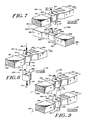
- Figs. 6-12 show alternative "dual separator" embodiments of the invention.
- two separators 56A and 56B each similar to the separator 10 described above in conjunction with Figs. 1-5, are positioned coaxially along the axis 13.
- the chambers 12A and 12B are mechanically coupled by a mechanical linkage indicated by dashed lines 57. That linkage couples the chambers 12A and 12B so that those chambers are selectively rotatable as a unit about the axis 13 by an actuator 59.
- elements corresponding to similar elements in Figs. 1-5 are identified with identical numerical reference designations but having a suffix designation A for the separator 56A and a suffix designation B for the separator 56B.
- a first magnetic circuit is established by the poles 18A and 22A along polar axis 58A and a second magnetic circuit is established by the poles 18B and 22B along polar axis 58B.
- the magnet poles 18A and 22A are aligned with and overlie the magnet poles 18B and 22B, and the chamber 12A is rotationally offset about the axis 13 by ninety degrees with respect to the chamber 12B.
- Fig. 12 shows a sectional view of the configuration of Fig. 6.
- the magnet poles 18A and 18B may be a single magnet pole and the magnet poles 22A and 22B may be a single magnetic pole.
- Figs. 6 and 12 With the configuration of Figs. 6 and 12, except during the switching of positions, one of the chambers 12A and 12B is in its capture phase of operation while the other is in its elutriation phase. As the orientation is being switched, the magnetic field assists the switching since as the reluctance between the poles of one magnetic circuit increases in the chamber being switched from its capture position, the reluctance between the poles of the other magnetic circuit decreases in the chamber being switched from its elutriation position. Consequently, the configuration of Figs. 6 and 12 requires less power to switch the chambers 12A and 12B between their operating positions, compared to that required for a similar single separator in the form of the separator 10, and a relatively low power actuator 59 may be used to accomplish the switching.
- Fig. 7 shows a dual separator configuration similar to that of Fig. 6, except that the magnet poles 18A and 22A are rotationally offset from the magnet poles 18B and 22B by ninety degrees about the axis 13, and the chambers 12A and 12B are aligned with each other.
- This configuration is functionally equivalent to the configuration of Fig. 6.
- the other is in its elutriation position, and the switching of chambers 12A and 12B between positions is assisted by the magnetic field.
- only a relatively low power actuator 59 is required, compared to a similar single separator.
- Fig. 8 shows another dual separator configuration.
- a single pair of magnetic poles 18A and 22A is used in conjunction with the actuator 59.
- the chamber 12A is rotationally offset from the chamber 12B by ninety degrees about the axis 13.
- the switching of the chambers both rotationally and axially is assisted by the magnetic field so that either chamber 12A is in its capture position in the magnetic field between poles 18A and 22A or chamber 12B is in its capture position in that field, while the other chamber is positioned outside the field.
- the separators 56A and 56B are preferably operated independently so that one separator is always operated in its capture phase, while the other separator is operated in its elutriation phase.
- This simultaneous filtering and flushing in the separator pair provides efficient operation with high system throughput.
- Different samples, or "splits" of a single sample can be exposed to the same or different protocols in the two separators 56A and 56B.
- the two capture phases may differ in reagents and/or flow rates, as can the two elutriation phases.
- the two chambers 12A and 12B may differ in their segment or internal geometry or in the material, geometry, dimensions or filling factor of their matrices 30. Further, in the configurations of Figs. 6 and 7 the two magnetization circuits may differ in their magnetization intensities or other characteristics. The great variety of potential protocols is of particular value when particles or cells must be separated from ones similar in many of their properties.
- Figs. 9, 10 and 11 show configurations similar to those in Figs. 6, 7 and 8, respectively, except that in each configuration, the chambers 12A and 12B are both aligned in the same manner with respect to the magnetic field. Consequently, each configuration requires a more powerful rotational actuator than its counterpart configuration in the respective ones of Figs. 6, 7 and 8. In effect twice the power is required as for a single separator comparable to one of the separators 56A or 56B.
- the configuration of Fig. 11 also requires an actuator that provides a substantial linear force along the common axis 13, in addition to the required rotary motion.
- the separators 56A and 56B may be operated independently to obtain the advantages described for the configurations of Figs. 6 and 7, but the latter offer better throughput and require less powerful activators 59.
- the two separators operated in series with port 16B being coupled to port 14A in the configurations of Figs. 9 and 10
- a single sample can undergo a compound filtration wherein any combination of chamber, matrix, and magnetization characteristics may be individually selected for the two chambers 12A and 12 .
- additional flexibility is obtained, e.g. to fractionate cells according to type or the same type according to some useful differentiating characteristic.
- these configurations can provide larger processed volumes per operational cycle, if ports 14A and 16A of chamber 12A are connected to the corresponding ports of chamber 12B and the two chambers have equivalent filtration characteristics.
- Fig. 11 can more readily be designed to permit repeated sequential use of only chamber 12A or chamber 12B than can the configuration of Fig. 8. In some cases it may be advantageous to operate separators 56A and 56B in series in this configuration, with port 16B being coupled to 14A and a lesser matrix filling factor being used in chamber 12B, to provide a mechanical prefilter for the magnetic filtration done in chamber 12A.
- Fig. 13 shows a top view of an alternative form of the invention including two separators 60 and 62, for example, each having the same form as the separator 10.
- Two horseshoe, or C-shaped, permanent magnets 66 and 68 are adapted to provide the magnetic field used with the separators 60 and 62. This arrangement is particularly easy to implement with readily available magnets.
- Each of the C-shaped magnets may also be effected by a sequential array of separate magnets, where between adjacent magnets can be another separator, or flux coupler if needed.
- either of the separators 60 or 62 can be replaced with a high permeability element so that a single separator system may be established.
- the separators 60 and 62 each may be dual separators, for example, as shown in Figs. 6-12, with the addition of another set of magnets, as necessary.
Landscapes
- Physical Or Chemical Processes And Apparatus (AREA)
- External Artificial Organs (AREA)
- Separation Of Solids By Using Liquids Or Pneumatic Power (AREA)
Abstract
Description
- The subject matter of this application is related to the subject matter of US-A-4 666 595 (& EP-A-236 449) entitled "Apparatus For Acoustically Removing Particles from a Magnetic Separation Matrix" filed on even date herewith.
- The present invention is in the field of instrumentation and more particularly relates to apparatus for magnetically separating particles from a liquid medium.
- The magnetic separation of solid material from a fluid medium has been accomplished in the prior art for processes where there was no concern for the integrity of the separated material. By way of example, processes are well known for separation of iron oxides from a mineral slurry. In practice, these separation processes lead to harsh physical interaction among the separated particles as well as between the separated particles and the separation matrix. Generally, there is no need in such fields of magnetic separation to be concerned about the intactness of the separated particles, although there is often concern with maintaining the integrity of the matrix.
- In other applications of magnetic separation, there is a concern about integrity of separated particles. For example, there is the need to separate intact living, biological cells from a fluid carrier, so that those cells may be analyzed. As another example, a fragilely connected aggregate of particles may be considered as a "particle" for which separation from a carrier fluid is desired while maintaining the aggregate relationship. One known separation technique useful in these fields is high-gradient magnetic separation, HGMS.
- In prior art HGMS systems, the collection of particles occurs on a matrix of magnetic wires, fibers, spheres or other high permeability members situated in a magnetic flux. Generally, such matrices are characterized by interstitial spaces through which the particles and carrier fluid may pass. As the particles pass through the matrix, each particle experiences a magnetic force toward the matrix elements proportional to

where ψp is the susceptibility of the particle, ψf is the susceptibility of the carrier fluid, Vp is the volume of the particle, H is the magnetic field intensity and x is a spatial dimension away from the matrix surface. In a paramagnetic mode of operation, where ψp exceeds ψf, that is where the particles are more "magnetic" than the carrier fluid, the particles are attracted to the elements of the matrix in the "strong field" regions at those elements. In a diamagnetic mode of operation, where ψf exceeds ψp, that is, where the carrier fluid is more "magnetic" than the particles, the particles are repelled from the strong field regions, but may be attracted to the weak or low field regions, at the matrix elements. - In a capture phase of operation, a fluid carrying the particles-to-be-separated is passed through the matrix at flow rates sufficiently low that magnetic attractive forces on the particles in the matrix exceed viscous and gravitational forces. As a consequence, those particles are held, or captured, against portions of the matrix while the carrier fluid exits the matrix. An elutriation phase may then be initiated to retrieve the captured particles from the matrix, for example, for subsequent analysis.
- In HGMS systems where the magnetic flux is generated by an electromagnet, or by a permanent magnet whose flux is by some means removed from the matrix during the elutriation phase, particles can be released from the matrix following their collection from the particle-laden carrier by first interrupting drive current to the winding of the electromagnet, or removing the permanent magnet flux from the matrix. However, residual magnetism in the system may cause some particles to be held by the matrix. Then the velocity at which the elutriation fluid is driven through the matrix may be selectively increased to remove the non-released particles from the matrix.
- In HGMS systems where the magnetic flux is generated by permanent magnets, and the matrix is maintained within the magnetic flux path at all times, that flux may continue to cause retention of the captured particles even upon the introduction of an elutriation fluid. The common method for elutriating the captured particles in this case is to appreciably increase fluid flow rates, so that the viscous drag forces exceed the magnetic retention forces; the captured particles are thus flushed off the matrix. This latter approach has been widely used with inorganic particles, but has been less successful when applied to separation of fragile particles such as intact living biological cells. Cellular debris observed in the flush effluent, particularly when old bloods are subjected to this method of cell elutriation, demonstrate that the method is too harsh for use with many clinical specimens.
- As a specific example of prior art relating to magnetic separator apparatus, DE-A-3,314,923 discloses a separator apparatus for separating magnetic particles from a fluid medium, wherein the apparatus comprises a rotatable magnet to magnetise and demagnetise the surrounding matrix.
- It is an object of the present invention to provide an improved apparatus for magnetically removing particles from a fluid medium.
- Another object is to provide an improved apparatus for magnetically capturing, and providing the intact removal therefrom of, fragile particles in a fluid medium.
- Yet another object is to provide an improved apparatus for magnetically capturing, and providing the removal therefrom of, intact biological cells from a fluid medium.
- According to the present invention, there is provided separator apparatus for separating magnetic particles from a fluid medium, comprising a separator including a housing defining a flow chamber having at least one input port and at least one output port and extending along a reference axis, said chamber defining a fluid flow path therethrough from one of said input ports to one of said output ports, a high magnetic permeability, interstitial separation matrix positioned within said flow chamber whereby fluid flowing between said input and output ports passes substantially through interstices in said matrix, a magnetizing means for selectively coupling magnetic flux to said matrix, wherein the said magnetizing means includes two opposite polarity magnet poles positioned external to the flow chamber and on opposite sides of said reference axis and wherein the flow chamber includes within the said housing relatively high magnetic permeability elements external to the said matrix, the said elements including means for establishing a flux path between the poles of said magnetizing means in each of a first position and a second position at said chamber, and the flow chamber is selectively rotatable about the said reference axis between the said first position and the said second position, whereby when said chamber is in the first position, a first flux path is established from one magnet pole of the magnetizing means through the matrix to the other magnet pole of the magnetizing means, and when said chamber is in the second position, a relatively low reluctance second flux path is established from the said one magnet pole of the magnetizing means through the said elements to said other magnet pole of the magnetizing means substantially external to said matrix.
- The invention is directed to the magnetic separation of fragile particles, such as intact biological cells, from a fluid medium. Specifically, the invention provides a high gradient magnetic separation (HGMS) system having both a flow chamber housing an interstitial separation matrix and associated magnetizing apparatus for coupling magnetic flux to the matrix. The interstitial matrix includes high magnetic permeability wires, fibers, spheres or the like and has interstices through which a carrier fluid carrying the cells-to-be-separated may be passed. The magnetizing apparatus includes a permanent magnet having opposing North and South poles and field-guiding pole pieces, external to the flow chamber. The flow chamber comprises a dual-position flux-coupler. The flux-coupler is operative in a first position in the capture phase and in a second position in an elutriation phase.
- In the capture phase, the flux-coupler is positioned to permit the magnetic flux from one magnetic pole to pass through the matrix to the other magnetic pole. As the carrier fluid flows through the interstices of the matrix in this phase, input fluid particles for which the magnetic attractive forces exceed viscous and gravitational forces (such as blood cells) are retained in the matrix.
- In the elutriation phase, the flux-coupler is positioned so that magnetic flux is diverted away from the matrix. In this phase, the appreciable reduction or elimination of magnetic flux from the matrix permits viscous forces of the fluid to remove the captured particles from the matrix at low flow velocities. A HGMS system of the type taught by the invention is capable of non-destructively separating fragile particles, e.g., intact blood cells, from a carrier fluid.
- In accordance with another aspect of the invention, an acoustic removal apparatus is incorporated into the flux diverting flow chamber to aid in dislodging captured particles from the matrix in the elutriation phase. The acoustical removal apparatus includes a piezoelectric transducer, which is acoustically coupled to the matrix, and an associated drive circuit. By way of example, the piezoelectric transducer may be affixed to a wall of the chamber housing the matrix with the transducer being in fluid communication with the matrix. Alternatively, the piezoelectric transducer may be mechanically coupled to the matrix.
- With this aspect of the invention, the HGMS system may operate with the flux coupler in its first position and otherwise operate in a conventional manner in the capture phase, whereby fragile particles are selectively captured magnetically from a carrier fluid passing through the matrix, with those captured particles being held in place within the matrix.
- In the elutriation phase, with the flux coupler in its second position so that flux is diverted from the matrix, an elutriation fluid is passed through the matrix. For applications where minimum elutriation velocities are essential, the drive circuit excites the piezoelectric transducer. In response to the excitation, the transducer establishes acoustic waves in the elutriation fluid passing through the matrix, vibrating the matrix itself. Depending upon the mechanical impedances within the flow chamber, the acoustic waves may be ultrasonic. The acoustic waves and matrix vibration operate to dislodge the intact cells from the matrix, permitting even lower elutriation flow rates than may be necessary using the flux-diverting features of the invention alone.
- In various forms of the invention, a single separator can be used, or alternatively, pairs of mechanically coupled separators can be arranged in dual separator configurations.
- The foregoing and other objects of this invention, the various features thereof, as well as the invention itself, may be more fully understood from the following description, when read together with the accompanying drawings in which:
- Fig. 1 shows a perspective view of a separator constructed in accordance with the present invention;
- Figs. 2 and 3 show vertical sectional views of the separator of Fig. 1;
- Figs. 4 and 5 show horizontal sectional views of the separator of Fig. 1;
- Figs. 6-11 show dual separator embodiments of the invention;
- Fig. 12 shows a sectional view of the dual separator embodiment of Fig. 6; and
- Fig. 13 shows an alternative dual separator embodiment of the invention.
- Figs. 1-5 show a
separator 10 for a high-gradient magnetic separation (HGMS) system. Theseparator 10 of the present embodiment is disclosed with a permanent magnet for generating the magnetic field used in particle separation. The invention is also applicable to an electromagnet-based HGMS system, where the separation magnetic field is generated with an electromagnet and the removal of captured particles may be achieved either with the magnet energized or de-energized. - The
separator 10 includes a generallycylindrical flow chamber 12 extending along areference axis 13 and having an input port 14 and an end member 14' and anoutput port 16 and anend member 16'. In other forms of the invention, additional input and output ports can also be provided forflow chamber 12. In the presently described embodiment, theaxis 13 is aligned with the local vertical. Thechamber 12 is adapted to permit fluid flow from the port 14 to theport 16 generally along theflow axis 17. A permanent magnet assembly is exterior to thechamber 12. The magnet assembly includes aNorth pole 18 and associated high permeability field-convergingpole piece 20 and aSouth pole 22 and associated high permeability field-convergingpole piece 24. Thepole pieces flow chamber 12, establish a flux path between thepoles poles reference line 26 is shown on theend piece 16' which passes throughaxis 13 andaxis 17. Thatreference line 26 is indicative in the Figures of the angular orientation of thechamber 12 aboutaxis 13. - As shown in the sectional views of Figs. 2-5, the
chamber 12 includes a high permeability,interstitial separation matrix 30. Thematrix 30 is positioned along theaxis 17 within theflow chamber 12 in a manner such that fluid driven between theports 14 and 16 passes substantially through thematrix 30. Thematrix 30 is a high permeability assembly constructed of magnetic wires, fibers, spheres, or the like, in a conventional fashion, having interstices large enough to permit the carrier fluid and particles to flow therethrough. By way of example, the matrix elements may be 5-15% of the chamber's interior volume. - As shown in Figs. 1-5, within the
matrix 30, theflow axis 17 is offset with respect to thereference axis 13, which in this embodiment is aligned with the local vertical. In other forms of the invention, theflow axis 17 may be offset from the vertical at any angle in the range zero to ninety degrees. Optimally, the offset of theaxis 17 is substantially equal to forty-five degrees, although other orientations may be used. In the illustrated embodiment with the input 14 lower than theexit port 16, the fluid flow through thechamber 12 includes a directed component opposite to the local gravitational field. As a result, the gravitational field assists the separation process by causing a relative slowing of the particle flow in the carrier fluid. - In the preferred embodiment, the
chamber 12 is formed from cylindricalsection sidewall members 40 and 42, which are non-magnetic, i.e. having low magnetic permeability, and cylindricalsection sidewall members members reference axis 13. Theentire flow chamber 12 is selectively rotatable about theaxis 13 so that in a first position as shown in Figs. 1, 2 and 4, a flux path is established from thepole 18 through thepole piece 20,sidewall member 44,matrix 30,sidewall member 46, andpole piece 24 to thepole 22. In a second position of thechamber 12, where thechamber 12 is offset by ninety degrees with respect to the first position, as shown in Figs. 3 and 5, a low-reluctance flux path is established from thepole 18 through thepole piece 20, through bothsidewall members pole piece 24 to thepole 22, so that the flux substantially by-passes thematrix 30. The principal flux paths for the two positions of thechamber 12 are indicated by the arrows in Figs. 4 and 5, respectively. In the illustrated embodiment the reluctance of the principal flux path illustrated in Fig. 4 is relatively high compared to that of the principal flux path illustrated in Fig. 5. - While not necessary for all aspects of the present invention, in another embodiment a
piezoelectric plate 52 is mounted in or on one wall (e.g. wall 40) of thechamber 12. Theplate 52 is coupled to a drive network 53. A back-loading element 54 may be used for quarter-wave impedance matching of the load to thepiezoelectric plate 52, as is known in the art of ultrasonic transducers. In the illustrated embodiment theplate 52 is mounted on, but electrically insulated from, thesidewall 40 of thechamber 12 and is in mechanical contact with thematrix 30. In other forms of the invention, theplate 52 may be spaced apart from (but in fluidic coupling with) thematrix 30. Theplate 52 may be exposed to the fluid containing the particles to be separated, or isolated from it by a thin membrane, insulating film or the like. - The preferred embodiment is particularly adapted to remove intact biological cells (such as erythrocytes) from a fluid medium (such as whole blood). In this embodiment a fluid driver, or pump, is adapted to drive the fluid medium through the
chamber 12 in the capture phase of operation. During this capture phase, thechamber 12 is in the position shown in Figs. 1, 2 and 4, theplate 52 is passive, and the magnetic field passes through thematrix 30. The cells passing in close proximity to the matrix elements are held, or captured, by those elements due to the forces generated on these particles by the magnetic field, as in conventional HGMS system operation. - As the
matrix 30 loading capacity is approached, an elutriation fluid may be substituted for the feed fluid and the elutriation phase begun. During this phase, thechamber 12 is in the position shown in Figs. 3 and 5 whereby the magnetic field is shunted through thesidewalls matrix 30. Relatively low flow rates, compared to that required by the prior art, suffice to flush the captured particles from thematrix 30, even in the continuing presence of the magnetizing field. - Optionally, in the illustrated embodiment including the
piezoelectric plate 52, to permit even lower elutriation flow rates to be used, the drive network 53 drives theplate 52 to generate a high frequency, e.g. 15 KHz, acoustic wave through the fluid inchamber 12. The drive waveform generated by network 53 may be a pulse or pulse train, for example, from an energy storage circuit.
Alternatively, the drive waveform may be a periodic oscillation gated off after the captured particles are elutriated, or another suitable waveform. Regardless of the specific drive waveform utilized, acoustic waves set up by the plate in response to the drive dislodge the particles from the matrix, either by driving thematrix 30 mechanically, or by the action of the acoustic waves propagating through the chamber volume. As a result, the captured particles may be removed with lower flow rates than may be permitted by flux diversion alone. The reduction in flow rates during elutriation depends on the strength of the acoustic wave and is more effective with back-loading established byelement 54 on the outer surface of theplate 52. - Thus, with the present invention (either with or without the plate 52), the
magnet poles pole pieces flow chamber 12 form a magnetic switch, which by the mechanical rotation of theflow chamber 12 about theaxis 13 diverts the magnetizing flux around thematrix 30 during the elutriation phase. Although in the illustrated embodiment thematrix 30 is shown to be in direct contact with structural elements of thechamber 12, the matrix may alternatively be contained in a suitable, even disposable, cartridge which may be inserted into the rotatable structure of thechamber 12. Thepole pieces sidewall members sidewalls - When the
chamber 12 is in its second position, i.e. during elutriation, themagnetic segments matrix 30 is greatly reduced compared to the levels present during the capture phase. The captured particles may then be elutriated with correspondingly reduced fluid velocities, and the chamber may be returned to its capture position for introduction of further feed fluid. - In other embodiments, the sample may be diluted by providing a sampling chamber in one of the cylindrical segments (such as
segment 44 or 46) which is filled during the elutriation phase of the previous cycle. During the next capture phase, this sampling chamber is flushed into thechamber housing matrix 30. The flushing may be accomplished with a suitable fluid, such as isotonic saline containing a reductant or oxidant, in one type of blood-cell separation. - The present invention permits the elutriation fluid velocities to be reduced in proportion to the reduction in magnetization field strength in the
matrix 30, thus reducing both fluid-shear and matrix-collision forces acting on the cells and thereby decreasing cell fragmentation. This is particularly important when the separation of erythrocytes from whole blood is done to facilitate counting of platelets, where for at least two reasons such fragmentation must be minimized: (1) Each damaged cell may give rise to several fragments which fall within the size range of true platelets; and (2) Because such fragments are smaller than the original erythrocytes for which the matrix is optimized, they will be captured with comparatively low efficiency and so appear in the effluent with the true platelets. Also, in cases where it is desired to separate particles or cells bound to some separable cell or particle, low elutriation forces are essential if the cell and its tagging moiety are to remain associated. - An exemplary configuration can include tapered rectangular
cross-section pole pieces pole pieces rotary flow chamber 12. In this exemplary configuration a stop plunger was provided to prevent theflow chamber 12 from turning itself into the elutriation position. - With the
chamber 12 within the pole assembly, themagnet poles sidewalls matrix 30 within the chamber comprised AISI 430 wire 50 micra in diameter, filling approximately 15% of the chamber volume. - With this configuration, the
matrix 30 was magnetized at 1.0 T and one-day old blood was diluted in isotonic saline containing 10 mM dithionite and then passed through thematrix 30. For three capture phases, elutriation was performed by flushing at about 5 filter-volumes/sec with thechamber 12 in the capture position and with zero voltage applied to theplate 52, thereby simulating conventional HGMS operation. Then, for three capture phases, elutriation was performed by flushing at about 2 filter-volumes/sec, i.e. at an elutriation flow rate which was 40% of the prior rate, with thechamber 12 in the elutriation position, again with zero voltage applied to theplate 52, thereby operatively using the configuration of the present invention. In both cases average background-corrected separation efficiencies were calculated from data taken with a COULTER COUNTER® Model ZB. The data from the "conventional" operation showed 76.3% separation efficiency, and the data from the present invention, i.e. using the flux diverting chamber in its elutriation position, showed 81.6% separation efficiency. In addition, a COULTER® CHANNELYZER® unit was used in conjunction with the ZB Counter to determine whether cellular breakup had occurred. The data from the CHANNELYZER unit for the conventional elutriation samples showed a decided debris distribution overlying the usual platelet region. When the invention was used, the data from the CHANNELYZER unit showed a much smaller distribution in this region. The data from the CHANNELYZER unit is supported by the 5% higher separation efficiency for the invention: Because fewer erythrocytes are fragmented during elutriation, more appear to be captured. This is particularly advantageous if erythrocytes are to be removed from a sample intended for platelet counting, since what is important is the ratio of platelets to red cells in the effluent during the capture phase; this ratio may be improved by both better erythrocyte capture and fewer platelet-sized erythrocytic fragments. - Figs. 6-12 show alternative "dual separator" embodiments of the invention. In those figures, two
separators 56A and 56B, each similar to theseparator 10 described above in conjunction with Figs. 1-5, are positioned coaxially along theaxis 13. Thechambers 12A and 12B are mechanically coupled by a mechanical linkage indicated by dashedlines 57. That linkage couples thechambers 12A and 12B so that those chambers are selectively rotatable as a unit about theaxis 13 by anactuator 59. In Figs. 6-12, elements corresponding to similar elements in Figs. 1-5 are identified with identical numerical reference designations but having a suffix designation A for theseparator 56A and a suffix designation B for the separator 56B. - In the configuration of Fig. 6, a first magnetic circuit is established by the
poles polar axis 58A and a second magnetic circuit is established by thepoles 18B and 22B along polar axis 58B. Themagnet poles magnet poles 18B and 22B, and thechamber 12A is rotationally offset about theaxis 13 by ninety degrees with respect to the chamber 12B. Fig. 12 shows a sectional view of the configuration of Fig. 6. Alternatively, themagnet poles magnet poles 22A and 22B may be a single magnetic pole. - With the configuration of Figs. 6 and 12, when one of
chambers 12A and 12B is in its first, or capture, position, i.e., so that the magnetic flux from its associated magnet poles passes through its matrix, the other ofchambers 12A and 12B is in its second, or elutriation, position so that the magnetic flux from its associated magnet poles is shunted around its matrix. - With the configuration of Figs. 6 and 12, except during the switching of positions, one of the
chambers 12A and 12B is in its capture phase of operation while the other is in its elutriation phase. As the orientation is being switched, the magnetic field assists the switching since as the reluctance between the poles of one magnetic circuit increases in the chamber being switched from its capture position, the reluctance between the poles of the other magnetic circuit decreases in the chamber being switched from its elutriation position. Consequently, the configuration of Figs. 6 and 12 requires less power to switch thechambers 12A and 12B between their operating positions, compared to that required for a similar single separator in the form of theseparator 10, and a relativelylow power actuator 59 may be used to accomplish the switching. - Fig. 7 shows a dual separator configuration similar to that of Fig. 6, except that the
magnet poles magnet poles 18B and 22B by ninety degrees about theaxis 13, and thechambers 12A and 12B are aligned with each other. This configuration is functionally equivalent to the configuration of Fig. 6. Here, too, when one ofchambers 12A and 12B is in its capture position, the other is in its elutriation position, and the switching ofchambers 12A and 12B between positions is assisted by the magnetic field. Again, only a relativelylow power actuator 59 is required, compared to a similar single separator. - Fig. 8 shows another dual separator configuration. In that configuration, a single pair of
magnetic poles actuator 59. Thechamber 12A is rotationally offset from the chamber 12B by ninety degrees about theaxis 13. In operation, as thechambers 12A and 12B are rotated by theactuator 59, the switching of the chambers both rotationally and axially is assisted by the magnetic field so that eitherchamber 12A is in its capture position in the magnetic field betweenpoles low power actuator 59 is required since as the reluctance in the flux path between the poles increases in the chamber being switched from its capture position, the reluctance in that flux path decreases in the chamber being switched from its elutriation position, and the magnetic field assists the pull-in of the latter chamber. The configuration is particularly advantageous compared with those of Figs. 6 and 7 because only one-half of the magnetizing flux is required from themagnetic poles - In the configurations of each of Figs. 6-8, the
separators 56A and 56B are preferably operated independently so that one separator is always operated in its capture phase, while the other separator is operated in its elutriation phase. This simultaneous filtering and flushing in the separator pair provides efficient operation with high system throughput. Different samples, or "splits" of a single sample, can be exposed to the same or different protocols in the twoseparators 56A and 56B. For example, the two capture phases may differ in reagents and/or flow rates, as can the two elutriation phases. Additionally, in the configuration of Fig. 8 the twochambers 12A and 12B may differ in their segment or internal geometry or in the material, geometry, dimensions or filling factor of theirmatrices 30. Further, in the configurations of Figs. 6 and 7 the two magnetization circuits may differ in their magnetization intensities or other characteristics. The great variety of potential protocols is of particular value when particles or cells must be separated from ones similar in many of their properties. - Figs. 9, 10 and 11 show configurations similar to those in Figs. 6, 7 and 8, respectively, except that in each configuration, the
chambers 12A and 12B are both aligned in the same manner with respect to the magnetic field. Consequently, each configuration requires a more powerful rotational actuator than its counterpart configuration in the respective ones of Figs. 6, 7 and 8. In effect twice the power is required as for a single separator comparable to one of theseparators 56A or 56B. The configuration of Fig. 11 also requires an actuator that provides a substantial linear force along thecommon axis 13, in addition to the required rotary motion. - In each of the configurations of Figs. 9 and 10, the
separators 56A and 56B may be operated independently to obtain the advantages described for the configurations of Figs. 6 and 7, but the latter offer better throughput and require lesspowerful activators 59. However, with the two separators operated in series, with port 16B being coupled toport 14A in the configurations of Figs. 9 and 10, a single sample can undergo a compound filtration wherein any combination of chamber, matrix, and magnetization characteristics may be individually selected for the twochambers ports chamber 12A are connected to the corresponding ports of chamber 12B and the two chambers have equivalent filtration characteristics. - The configuration of Fig. 11 can more readily be designed to permit repeated sequential use of
only chamber 12A or chamber 12B than can the configuration of Fig. 8. In some cases it may be advantageous to operateseparators 56A and 56B in series in this configuration, with port 16B being coupled to 14A and a lesser matrix filling factor being used in chamber 12B, to provide a mechanical prefilter for the magnetic filtration done inchamber 12A. - Fig. 13 shows a top view of an alternative form of the invention including two
separators separator 10. Two horseshoe, or C-shaped,permanent magnets 66 and 68 are adapted to provide the magnetic field used with theseparators separators separators
Claims (10)
- Separator apparatus for separating magnetic particles from a fluid medium, comprising:
a separator (10) including:
a housing defining a flow chamber (12) having at least one input port (14) and at least one output port (16) and extending along a reference axis, said chamber defining a fluid flow path therethrough from one of said input ports to one of said output ports,
a high magnetic permeability, interstitial separation matrix (30) positioned within said flow chamber whereby fluid flowing between said input and output ports passes substantially through interstices in said matrix,
a magnetizing means (18, 22) for selectively coupling magnetic flux to said matrix,
wherein the said magnetizing means (18, 22) includes two opposite polarity magnet poles positioned external to the flow chamber (12) and on opposite sides of said reference axis and
wherein the flow chamber (12) includes within the said housing relatively high magnetic permeability elements (44, 46) external to the said matrix (30), the said elements including means for establishing a flux path between the poles of said magnetizing means in each of a first position and a second position at said chamber (12), and the flow chamber (12) is selectively rotatable about the said reference axis between the said first position and the said second position, whereby:
when said chamber is in the first position, a first flux path is established from one magnet pole of the magnetizing means through the matrix (30) to the other magnet pole of the magnetizing means, and
when said chamber is in the second position, a relatively low reluctance second flux path is established from the said one magnet pole of the magnetizing means through the said elements (44, 46) to said other magnet pole of the magnetizing means substantially external to said matrix. - A separator apparatus according to claim 1 comprising the first separator (e.g. 56A) and a second separator (56B) which is substantially similar to the first separator, wherein flow chambers of both the first and second separators are rigidly coupled whereby reference axes of the first and second separators are coaxial with a common axis.
- Separator apparatus according to claim 2 wherein the poles of the magnetizing means (18A, 22A) of the first separator (56A) are positioned along a first polar axis (58A) and the poles of a second magnetizing means of the second separator (58A) are positioned along a second polar axis (58B), wherein (see Fig. 6) the first polar axis (58A) is parallel to said second polar axis (58B), and the apparatus including means (57) for mechanically coupling the first and second flow chambers (12A, 12B) so that said first flow chamber (12A) is in its first position with respect to the magnetic poles of said first magnetizing means (18A, 22A) when the second flow chamber (12B) is in its second position with respect to the magnetic poles of said second magnetizing means (18B, 22B), and the first flow chamber (12A) is in its second position with respect to the magnet poles of the first magnetizing means when the second chamber (12B) is in its first position with respect to the magnet poles of the second magnetizing means.
- Separator apparatus according to claim 2 wherein the poles of the magnetizing means (18A, 22A) of the first separator (56A) are positioned along a first polar axis (58A) and the poles of a second magnetizing means of the second separator (56B) are positioned along a second polar axis (58B), wherein (see Fig. 9) the first polar axis (58A) is parallel to said second polar axis (58B), and the apparatus including means (57) for mechanically coupling the first and second flow chambers (12A, 12B) so that said first flow chamber (12A) is in its first position with respect to the magnetic poles of the first magnetizing means (18A, 22A) when the second flow chamber (12B) is in its first position with respect to the magnetic poles of the second magnetizing means (18B, 22B), and the first flow chamber (12A) is in its second position with respect to the magnet poles of the first magnetizing means when said second chamber is in its second position with respect to the magnet poles of the second magnetizing means.
- Separator apparatus according to claim 2 wherein the poles of the first magnetizing means (18A, 22A) of the first separator (56A) are positioned along a first polar axis (58A) and the poles of a second magnetizing means of the second separator (56B) are positioned along a second polar axis (58B), wherein (see Fig. 7) the first polar axis (58A) is perpendicular to the second polar axis (58B), and the apparatus including means (57) for mechanically coupling the first and second flow chambers (12A, 12B) so that the first flow chamber (12A) is in its first position with respect to the magnetic poles of the first magnetizing means (18A, 22A) when the second flow chamber (12B) is in its second position with respect to the magnetic poles of the second magnetizing means (18B, 22B), and the first flow chamber (12A) is in its second position with respect to the magnet poles of the first magnetizing means when the second chamber (12B) is in its first position with respect to the magnet poles of the second magnetizing means.
- Separator apparatus according to claim 2 wherein the poles of the first magnetizing means (18A, 22A) of the first separator (56A) are positioned along a first polar axis (58A) and the poles of a second magnetizing means of the second separator (56B) are positioned along a second polar axis (58B), wherein (see Fig. 10) the first polar axis (58A) is perpendicular to said second polar axis, and the apparatus including means (57) for mechanically coupling the first and second flow chambers (12A, 12B) so that the first flow chamber (12A) is in its first position with respect to the magnetic poles of the first magnetizing means (18A, 22A) when the second flow chamber (12B) is in its first position with respect to the magnetic poles of the second magnetizing means (18B, 22B), and the first flow chamber (12A) is in its second position with respect to the magnet poles of the first magnetizing means when the second chamber (12B) is in its second position with respect to the magnet poles of the second magnetizing means.
- Separator apparatus according to claim 2 wherein said first and second separators (56A, 56B) are movable between two positions along said common axis (13A), and
wherein first and second magnetizing means comprise a common pair of opposite polarity magnet poles (18A, 22A), said common pair being adapted to couple said magnetic flux substantially to one of said flow chambers (e.g. 12A) when said separators (56A, 56B) are in one of said positions and substantially to the other of said flow chambers (e.g. 12B) when the separators (56A, 56B) are in the other of said positions. - Separator apparatus according to claim 7 including means for controlling the orientation of said first and second flow chambers (12A, 12B) so that (Fig. 8) the first flow chamber (12A) is in its first position with respect to the common pair of magnetic poles when the second flow chamber (12B) is in its second position with respect to the common pair of magnetic poles, and the first flow chamber (12A) is in its second position with respect to the common pair of magnet poles when the second chamber (12B) is in its first position with respect to the common pair of magnet poles.
- Separator apparatus according to claim 7 including means for controlling the orientation of said first and second flow chambers (12A, 12B) so that (Fig. 11) the first flow chamber (12A) is in its first position with respect to the common pair of magnetic poles when the second flow chamber (12B) is in its first position with respect to the common pair of magnetic poles, and the first flow chamber (12A) is in its second position with respect to the common pair of magnet poles when the second chamber (12B) is in its second position with respect to the common pair of magnet poles.
- A separator apparatus according to claim 1 wherein said magnetizing means comprises a pair of C-shaped permanent magnets (66, 68) with the North pole of each of said magnets being positioned opposite the South pole of each of said magnets, wherein said flow chamber (e.g. 60) is positioned between one set of said oppositely positioned North and South poles, and further comprises means (not shown) to couple magnetic flux between said North and South poles of said other set or oppositely positioned North and South poles.
Priority Applications (1)
| Application Number | Priority Date | Filing Date | Title |
|---|---|---|---|
| AT86905637T ATE74788T1 (en) | 1985-09-16 | 1986-09-09 | FLOW CHAMBER WITH FLOW DEFLECTION FOR THE SEPARATION OF PARTICLES FROM A LIQUID MEDIUM BY HIGH-GRADIENT MAGNET SEPARATION TECHNOLOGY. |
Applications Claiming Priority (2)
| Application Number | Priority Date | Filing Date | Title |
|---|---|---|---|
| US776567 | 1985-09-16 | ||
| US06/776,567 US4664796A (en) | 1985-09-16 | 1985-09-16 | Flux diverting flow chamber for high gradient magnetic separation of particles from a liquid medium |
Publications (3)
| Publication Number | Publication Date |
|---|---|
| EP0237549A1 EP0237549A1 (en) | 1987-09-23 |
| EP0237549A4 EP0237549A4 (en) | 1988-09-28 |
| EP0237549B1 true EP0237549B1 (en) | 1992-04-15 |
Family
ID=25107762
Family Applications (1)
| Application Number | Title | Priority Date | Filing Date |
|---|---|---|---|
| EP86905637A Expired EP0237549B1 (en) | 1985-09-16 | 1986-09-09 | Flux diverting flow chamber for high gradient magnetic separation of particles from a liquid medium |
Country Status (6)
| Country | Link |
|---|---|
| US (1) | US4664796A (en) |
| EP (1) | EP0237549B1 (en) |
| JP (1) | JPS63501139A (en) |
| AT (1) | ATE74788T1 (en) |
| DE (1) | DE3684910D1 (en) |
| WO (1) | WO1987001608A1 (en) |
Cited By (2)
| Publication number | Priority date | Publication date | Assignee | Title |
|---|---|---|---|---|
| DE10354351B3 (en) * | 2003-11-20 | 2005-06-16 | november Aktiengesellschaft Gesellschaft für Molekulare Medizin | Method and apparatus for improved purification of a substance bound to paramagnetic microparticles |
| CN108580030A (en) * | 2018-03-29 | 2018-09-28 | 西北工业大学 | A kind of system and constrained procedure constraining non-diamagnetic substance in a non contact fashion |
Families Citing this family (49)
| Publication number | Priority date | Publication date | Assignee | Title |
|---|---|---|---|---|
| US5123901A (en) * | 1988-02-25 | 1992-06-23 | Carew E Bayne | Method for separating pathogenic or toxic agents from a body fluid and return to body |
| US5536475A (en) * | 1988-10-11 | 1996-07-16 | Baxter International Inc. | Apparatus for magnetic cell separation |
| US6020210A (en) * | 1988-12-28 | 2000-02-01 | Miltenvi Biotech Gmbh | Methods and materials for high gradient magnetic separation of biological materials |
| US5385707A (en) * | 1988-12-28 | 1995-01-31 | Stefan Miltenyi | Metal matrices for use in high gradient magnetic separation of biological materials and method for coating the same |
| ATE114507T1 (en) * | 1988-12-28 | 1994-12-15 | Stefan Miltenyi | METHODS AND MATERIALS FOR HIGH GRADUATION MAGNETIC SEPARATION OF BIOLOGICAL MATERIALS. |
| US5622831A (en) * | 1990-09-26 | 1997-04-22 | Immunivest Corporation | Methods and devices for manipulation of magnetically collected material |
| WO1994020855A1 (en) * | 1993-03-04 | 1994-09-15 | Sapidyne, Inc. | Assay flow apparatus and method |
| US5705059A (en) * | 1995-02-27 | 1998-01-06 | Miltenyi; Stefan | Magnetic separation apparatus |
| US5779892A (en) * | 1996-11-15 | 1998-07-14 | Miltenyi Biotec Gmbh | Magnetic separator with magnetic compensated release mechanism for separating biological material |
| ES2279600T3 (en) | 1998-03-12 | 2007-08-16 | Miltenyi Biotec Gmbh | MICROCOLUMN SYSTEM FOR MAGNETIC SEPARATION. |
| US7220596B2 (en) | 1998-04-15 | 2007-05-22 | Utah State University | Real time detection of antigens |
| NZ506590A (en) * | 1998-12-29 | 2002-10-25 | Thomas Adam Shine | A method of analysing a sample of free cells |
| US6159378A (en) * | 1999-02-23 | 2000-12-12 | Battelle Memorial Institute | Apparatus and method for handling magnetic particles in a fluid |
| CN1136923C (en) * | 2001-03-13 | 2004-02-04 | 张兴东 | Magnetizing device for moving magnetic field of blood magnet machine |
| US20030095897A1 (en) * | 2001-08-31 | 2003-05-22 | Grate Jay W. | Flow-controlled magnetic particle manipulation |
| US20030099954A1 (en) * | 2001-11-26 | 2003-05-29 | Stefan Miltenyi | Apparatus and method for modification of magnetically immobilized biomolecules |
| WO2003049530A2 (en) * | 2001-12-07 | 2003-06-19 | Dyax Corporation | Method and apparatus for washing magnetically responsive particles |
| US20030119057A1 (en) * | 2001-12-20 | 2003-06-26 | Board Of Regents | Forming and modifying dielectrically-engineered microparticles |
| EP1569510B1 (en) | 2002-09-27 | 2011-11-02 | The General Hospital Corporation | Microfluidic device for cell separation and uses thereof |
| US20040157219A1 (en) * | 2003-02-06 | 2004-08-12 | Jianrong Lou | Chemical treatment of biological samples for nucleic acid extraction and kits therefor |
| EP1776449A4 (en) * | 2004-03-03 | 2009-08-12 | Gen Hospital Corp | MAGNETIC DEVICE FOR ISOLATING CELLS AND BIOMOLECULES IN A MICROFLUIDIC ENVIRONMENT |
| US20050239091A1 (en) * | 2004-04-23 | 2005-10-27 | Collis Matthew P | Extraction of nucleic acids using small diameter magnetically-responsive particles |
| US20060024776A1 (en) * | 2004-08-02 | 2006-02-02 | Mcmillian Ray | Magnetic particle capture of whole intact organisms from clinical samples |
| JP5053089B2 (en) * | 2004-08-03 | 2012-10-17 | ベクトン・ディキンソン・アンド・カンパニー | Use of magnetic materials for direct isolation of compounds and fractionation of multicomponent samples |
| JP2008511816A (en) * | 2004-08-03 | 2008-04-17 | ベクトン・ディキンソン・アンド・カンパニー | Use of magnetic materials to separate samples |
| US20070196820A1 (en) | 2005-04-05 | 2007-08-23 | Ravi Kapur | Devices and methods for enrichment and alteration of cells and other particles |
| US20070026414A1 (en) * | 2005-07-29 | 2007-02-01 | Martin Fuchs | Devices and methods for enrichment and alteration of circulating tumor cells and other particles |
| US20070026413A1 (en) * | 2005-07-29 | 2007-02-01 | Mehmet Toner | Devices and methods for enrichment and alteration of circulating tumor cells and other particles |
| US20070026417A1 (en) * | 2005-07-29 | 2007-02-01 | Martin Fuchs | Devices and methods for enrichment and alteration of circulating tumor cells and other particles |
| US8921102B2 (en) | 2005-07-29 | 2014-12-30 | Gpb Scientific, Llc | Devices and methods for enrichment and alteration of circulating tumor cells and other particles |
| US20070059680A1 (en) * | 2005-09-15 | 2007-03-15 | Ravi Kapur | System for cell enrichment |
| US20070059719A1 (en) * | 2005-09-15 | 2007-03-15 | Michael Grisham | Business methods for prenatal Diagnosis |
| US20070059716A1 (en) * | 2005-09-15 | 2007-03-15 | Ulysses Balis | Methods for detecting fetal abnormality |
| US20070059683A1 (en) * | 2005-09-15 | 2007-03-15 | Tom Barber | Veterinary diagnostic system |
| US20070059718A1 (en) * | 2005-09-15 | 2007-03-15 | Mehmet Toner | Systems and methods for enrichment of analytes |
| EP1996931B1 (en) | 2005-12-28 | 2013-11-27 | The General Hospital Corporation | Blood cell sorting methods and systems |
| CA2692186C (en) * | 2007-06-29 | 2019-03-12 | Becton, Dickinson And Company | Methods for extraction and purification of components of biological samples |
| DE102007043281A1 (en) * | 2007-09-11 | 2009-05-28 | Sebastian Dr. med. Chakrit Bhakdi | Apparatus, materials and methods for high gradient magnetic separation of biological material |
| EP2306959A2 (en) * | 2008-07-11 | 2011-04-13 | The General Hospital Corporation | Magnetic apparatus for blood separation |
| JP2012176382A (en) * | 2011-02-28 | 2012-09-13 | Nippon Steel Engineering Co Ltd | Magnetic separation filter device |
| DE102011015321A1 (en) | 2011-03-28 | 2012-10-04 | Ralph Heindrichs | Method for separating leucocyte from blood, involves forming openings through which to-be-separated particles are deflected in separation channel |
| ES2837407T3 (en) | 2011-04-05 | 2021-06-30 | Purdue Research Foundation | Microfluidic system using microapertures for high throughput detection of entities |
| US9885642B2 (en) | 2011-04-27 | 2018-02-06 | Becton, Dickinson And Company | Devices and methods for separating magnetically labeled moieties in a sample |
| SG11201807053TA (en) | 2016-03-07 | 2018-09-27 | X Zell Inc | Compositions and methods for identifying rare cells |
| EP3693739A1 (en) | 2019-02-06 | 2020-08-12 | Stefan Schreier | Method and device for isolating desired cells from a sample of nonmagnetic biological material |
| US11791590B2 (en) * | 2020-04-22 | 2023-10-17 | Keysight Technologies, Inc. | Magnetic cable connection device and adapator |
| EP4115981A1 (en) * | 2021-07-09 | 2023-01-11 | Miltenyi Biotec B.V. & Co. KG | Magnetic separation with rotating magnetic field/rotating column |
| DE202021105458U1 (en) | 2021-10-08 | 2023-01-24 | Sanolibio Co., Ltd. | Device for the magnetic purification of biological samples |
| EP4469208A4 (en) * | 2022-01-28 | 2026-06-03 | Taco Inc | SWITCHABLE MAGNETIC FILTER |
Family Cites Families (36)
| Publication number | Priority date | Publication date | Assignee | Title |
|---|---|---|---|---|
| DE624224C (en) * | 1933-01-31 | 1936-01-16 | Ernst Moyat | Magnetic separator |
| US2430157A (en) * | 1939-07-29 | 1947-11-04 | Jr William Byrd | Magnetic separator for removing finely divided magnetic material from liquids |
| US2329893A (en) * | 1940-09-10 | 1943-09-21 | Magnetos Lucifer S A | Magnetic device for the purification of fluids |
| US2823803A (en) * | 1955-09-12 | 1958-02-18 | Sinclair Machine Products Inc | Magnetic filter |
| US3142787A (en) * | 1962-04-27 | 1964-07-28 | Brown & Sharpe Mfg | Permanent magnetic block |
| US3164756A (en) * | 1962-05-16 | 1965-01-05 | Nix Steingroeve Elektro Physik | Adjustable permanent magnet |
| US3367612A (en) * | 1966-01-11 | 1968-02-06 | Enco Mfg Company | Adjustable indicator holder |
| US3489280A (en) * | 1966-02-03 | 1970-01-13 | Eriez Mfg Co | Magnetic separator having field shaping poles |
| US3375925A (en) * | 1966-10-18 | 1968-04-02 | Carpco Res & Engineering Inc | Magnetic separator |
| US3567026A (en) * | 1968-09-20 | 1971-03-02 | Massachusetts Inst Technology | Magnetic device |
| US3616925A (en) * | 1969-03-19 | 1971-11-02 | United Conveyor Corp | Apparatus for dewatering granular material |
| US3700555A (en) * | 1970-10-12 | 1972-10-24 | Technicon Instr | Method and apparatus for lymphocyte separation from blood |
| US3709791A (en) * | 1971-04-13 | 1973-01-09 | Technicon Instr | Method and apparatus for lymphocyte separation from blood |
| CA981010A (en) * | 1971-04-20 | 1976-01-06 | Matsushita Electric Industrial Co., Ltd. | Piezoelectric ceramic compositions |
| BE792843A (en) * | 1971-12-22 | 1973-03-30 | Kraftwerk Union Ag | ELECTROMAGNETIC FILTER FOR IRON OXIDES |
| US3812629A (en) * | 1972-08-15 | 1974-05-28 | P Campbell | Workholder |
| US4054513A (en) * | 1973-07-10 | 1977-10-18 | English Clays Lovering Pochin & Company Limited | Magnetic separation, method and apparatus |
| US4116829A (en) * | 1974-01-18 | 1978-09-26 | English Clays Lovering Pochin & Company Limited | Magnetic separation, method and apparatus |
| GB1501396A (en) * | 1974-07-19 | 1978-02-15 | English Clays Lovering Pochin | Magnetic separators |
| US4051023A (en) * | 1975-04-11 | 1977-09-27 | Eriez Magnetics | Combination electromagnet and permanent magnet separator |
| DE2517364A1 (en) * | 1975-04-19 | 1976-10-28 | Max Baermann | SWITCHABLE, PERMANENT MAGNETIC HOLDING DEVICE |
| DE2628095C3 (en) * | 1976-06-23 | 1981-08-06 | Siemens AG, 1000 Berlin und 8000 München | Magnetic separation device |
| JPS5387033A (en) * | 1977-01-10 | 1978-08-01 | Etsurou Fujita | Method and apparatus for preventing environmental pollution by processing combustible fuel flow in magnetic field |
| JPS53130572A (en) * | 1977-04-05 | 1978-11-14 | Tdk Electronics Co Ltd | Highhgradient magnetic separator using amorphous magnetic alloy |
| GB1599824A (en) * | 1978-02-27 | 1981-10-07 | Stekly Z J J | Magnetic separator |
| IT7823323V0 (en) * | 1978-11-17 | 1978-11-17 | Cardone Tecnomagnetica | MAGNETIC LIFTER WITH MANUAL CONTROL. |
| JPS5578505A (en) * | 1978-12-08 | 1980-06-13 | Kanetsuu Kogyo Kk | Attraction type magnetic device |
| US4314219A (en) * | 1979-04-17 | 1982-02-02 | Hitachi Metals, Ltd. | Permanent magnet type lifting device |
| US4244822A (en) * | 1979-08-09 | 1981-01-13 | The Babcock & Wilcox Company | Industrial technique magnetic apparatus |
| US4261815A (en) * | 1979-12-31 | 1981-04-14 | Massachusetts Institute Of Technology | Magnetic separator and method |
| DE3123731A1 (en) * | 1981-06-15 | 1982-12-30 | Basf Ag, 6700 Ludwigshafen | CHLORIC ACETIC CYCLOHEXYLAMIDES, THEIR PRODUCTION, THEIR USE FOR CONTROLLING HERBICIDES, AND A MEDIUM FOR THIS |
| CA1184532A (en) * | 1981-06-19 | 1985-03-26 | Severin F. Sverre | Magnetic water conditioning device |
| DE3247522A1 (en) * | 1982-12-22 | 1984-06-28 | Siemens AG, 1000 Berlin und 8000 München | DEVICE OF HIGHLY GRADIENT MAGNETIC SEPARATION TECHNOLOGY FOR DEPOSITING MAGNETIZABLE PARTICLES |
| DE3312207A1 (en) * | 1983-04-05 | 1984-10-11 | Ukrainskij institut inženerov vodnogo chozjajstva, Rovno | Device for separating ferromagnetic materials from liquid media |
| DE3314923C2 (en) * | 1983-04-25 | 1986-10-02 | Ukrainskij institut inženerov vodnogo chozjajstva, Rovno | Magnetic separator |
| JPH119475A (en) * | 1997-06-25 | 1999-01-19 | Zojirushi Corp | Liquid container flow control device |
-
1985
- 1985-09-16 US US06/776,567 patent/US4664796A/en not_active Expired - Fee Related
-
1986
- 1986-09-09 DE DE8686905637T patent/DE3684910D1/en not_active Expired - Fee Related
- 1986-09-09 EP EP86905637A patent/EP0237549B1/en not_active Expired
- 1986-09-09 AT AT86905637T patent/ATE74788T1/en active
- 1986-09-09 JP JP61504857A patent/JPS63501139A/en active Pending
- 1986-09-09 WO PCT/US1986/001853 patent/WO1987001608A1/en not_active Ceased
Cited By (2)
| Publication number | Priority date | Publication date | Assignee | Title |
|---|---|---|---|---|
| DE10354351B3 (en) * | 2003-11-20 | 2005-06-16 | november Aktiengesellschaft Gesellschaft für Molekulare Medizin | Method and apparatus for improved purification of a substance bound to paramagnetic microparticles |
| CN108580030A (en) * | 2018-03-29 | 2018-09-28 | 西北工业大学 | A kind of system and constrained procedure constraining non-diamagnetic substance in a non contact fashion |
Also Published As
| Publication number | Publication date |
|---|---|
| ATE74788T1 (en) | 1992-05-15 |
| WO1987001608A1 (en) | 1987-03-26 |
| DE3684910D1 (en) | 1992-05-21 |
| EP0237549A1 (en) | 1987-09-23 |
| US4664796A (en) | 1987-05-12 |
| JPS63501139A (en) | 1988-04-28 |
| EP0237549A4 (en) | 1988-09-28 |
Similar Documents
| Publication | Publication Date | Title |
|---|---|---|
| US4664796A (en) | Flux diverting flow chamber for high gradient magnetic separation of particles from a liquid medium | |
| EP0236449B1 (en) | Apparatus for acoustically removing particles from a magnetic separation matrix | |
| AU561825B2 (en) | Magnetic separator | |
| US3567026A (en) | Magnetic device | |
| US3676337A (en) | Process for magnetic separation | |
| CN1263548C (en) | Continuous magnetic separation of components from mixture | |
| US4663029A (en) | Method and apparatus for continuous magnetic separation | |
| EP1350095B1 (en) | Method and apparatus for combined magnetophoretic and dielectrophoretic manipulation of analyte mixtures | |
| EP2185289B1 (en) | Microfluidic separation system | |
| JPS61293562A (en) | Separator for magnetically removing magnetizable particle | |
| CN102470373B (en) | Apparatus for the enrichment of magnetic particles | |
| Verbarg et al. | Spinning magnetic trap for automated microfluidic assay systems | |
| KR20210086630A (en) | magnetic separation | |
| CN2306837Y (en) | High field strength electromagnetic pulsation high gradient magnetic separator | |
| CA1285246C (en) | Diverting flow chamber | |
| US6045705A (en) | Magnetic separation | |
| JP2777787B2 (en) | Wet magnetic sorter | |
| Liakopoulos et al. | A bio-magnetic bead separator on glass chips using semi-encapsulated spiral electromagnets | |
| Watson et al. | Single-Wire Magnetic Separation: a Diagnostic Tool for Mineral Processing.(Retroactive Coverage) | |
| CA1285247C (en) | Acoustical removal of particles from magnetic matrix | |
| HK40051566A (en) | Magnetic separation | |
| JPS62241518A (en) | Cleaning device | |
| JPS5969122A (en) | Electromagnetic separation apparatus | |
| HK1032554B (en) | Continuous magnetic separation of components from a mixture |
Legal Events
| Date | Code | Title | Description |
|---|---|---|---|
| PUAI | Public reference made under article 153(3) epc to a published international application that has entered the european phase |
Free format text: ORIGINAL CODE: 0009012 |
|
| AK | Designated contracting states |
Kind code of ref document: A1 Designated state(s): AT BE CH DE FR GB IT LI LU NL SE |
|
| 17P | Request for examination filed |
Effective date: 19870829 |
|
| A4 | Supplementary search report drawn up and despatched |
Effective date: 19880928 |
|
| 17Q | First examination report despatched |
Effective date: 19901213 |
|
| GRAA | (expected) grant |
Free format text: ORIGINAL CODE: 0009210 |
|
| AK | Designated contracting states |
Kind code of ref document: B1 Designated state(s): AT BE CH DE FR GB IT LI LU NL SE |
|
| PG25 | Lapsed in a contracting state [announced via postgrant information from national office to epo] |
Ref country code: IT Free format text: LAPSE BECAUSE OF FAILURE TO SUBMIT A TRANSLATION OF THE DESCRIPTION OR TO PAY THE FEE WITHIN THE PRE;WARNING: LAPSES OF ITALIAN PATENTS WITH EFFECTIVE DATE BEFORE 2007 MAY HAVE OCCURRED AT ANY TIME BEFORE 2007. THE CORRECT EFFECTIVE DATE MAY BE DIFFERENT FROM THE ONE RECORDED.SCRIBED TIME-LIMIT Effective date: 19920415 Ref country code: AT Effective date: 19920415 Ref country code: FR Effective date: 19920415 Ref country code: SE Effective date: 19920415 |
|
| REF | Corresponds to: |
Ref document number: 74788 Country of ref document: AT Date of ref document: 19920515 Kind code of ref document: T |
|
| REF | Corresponds to: |
Ref document number: 3684910 Country of ref document: DE Date of ref document: 19920521 |
|
| REG | Reference to a national code |
Ref country code: CH Ref legal event code: PUE Owner name: COULTER CORPORATION |
|
| REG | Reference to a national code |
Ref country code: GB Ref legal event code: 732 |
|
| EN | Fr: translation not filed | ||
| PG25 | Lapsed in a contracting state [announced via postgrant information from national office to epo] |
Ref country code: LU Free format text: LAPSE BECAUSE OF NON-PAYMENT OF DUE FEES Effective date: 19920930 |
|
| PGFP | Annual fee paid to national office [announced via postgrant information from national office to epo] |
Ref country code: DE Payment date: 19920930 Year of fee payment: 7 |
|
| BECN | Be: change of holder's name |
Effective date: 19920415 |
|
| PLBE | No opposition filed within time limit |
Free format text: ORIGINAL CODE: 0009261 |
|
| STAA | Information on the status of an ep patent application or granted ep patent |
Free format text: STATUS: NO OPPOSITION FILED WITHIN TIME LIMIT |
|
| 26N | No opposition filed | ||
| PGFP | Annual fee paid to national office [announced via postgrant information from national office to epo] |
Ref country code: CH Payment date: 19930614 Year of fee payment: 8 |
|
| PGFP | Annual fee paid to national office [announced via postgrant information from national office to epo] |
Ref country code: GB Payment date: 19930621 Year of fee payment: 8 |
|
| PGFP | Annual fee paid to national office [announced via postgrant information from national office to epo] |
Ref country code: BE Payment date: 19930625 Year of fee payment: 8 |
|
| NLS | Nl: assignments of ep-patents |
Owner name: COULTER CORPORATION TE HIALEAH, FLORIDA, VER. ST. |
|
| PGFP | Annual fee paid to national office [announced via postgrant information from national office to epo] |
Ref country code: NL Payment date: 19930930 Year of fee payment: 8 |
|
| PG25 | Lapsed in a contracting state [announced via postgrant information from national office to epo] |
Ref country code: DE Effective date: 19940601 |
|
| PG25 | Lapsed in a contracting state [announced via postgrant information from national office to epo] |
Ref country code: GB Effective date: 19940909 |
|
| PG25 | Lapsed in a contracting state [announced via postgrant information from national office to epo] |
Ref country code: LI Effective date: 19940930 Ref country code: BE Effective date: 19940930 Ref country code: CH Effective date: 19940930 |
|
| BERE | Be: lapsed |
Owner name: COULTER CORP. Effective date: 19940930 |
|
| PG25 | Lapsed in a contracting state [announced via postgrant information from national office to epo] |
Ref country code: NL Effective date: 19950401 |
|
| GBPC | Gb: european patent ceased through non-payment of renewal fee |
Effective date: 19940909 |
|
| NLV4 | Nl: lapsed or anulled due to non-payment of the annual fee | ||
| REG | Reference to a national code |
Ref country code: CH Ref legal event code: PL |