EP0236927B1 - Automatic device for detaching the cam followers in a sewing machine - Google Patents
Automatic device for detaching the cam followers in a sewing machine Download PDFInfo
- Publication number
- EP0236927B1 EP0236927B1 EP87103071A EP87103071A EP0236927B1 EP 0236927 B1 EP0236927 B1 EP 0236927B1 EP 87103071 A EP87103071 A EP 87103071A EP 87103071 A EP87103071 A EP 87103071A EP 0236927 B1 EP0236927 B1 EP 0236927B1
- Authority
- EP
- European Patent Office
- Prior art keywords
- shaft
- knob
- cam
- cam follower
- rotation
- Prior art date
- Legal status (The legal status is an assumption and is not a legal conclusion. Google has not performed a legal analysis and makes no representation as to the accuracy of the status listed.)
- Expired
Links
- 238000009958 sewing Methods 0.000 title claims description 11
- 238000006073 displacement reaction Methods 0.000 claims description 6
- 230000008878 coupling Effects 0.000 description 2
- 238000010168 coupling process Methods 0.000 description 2
- 238000005859 coupling reaction Methods 0.000 description 2
- 230000005540 biological transmission Effects 0.000 description 1
- 238000010276 construction Methods 0.000 description 1
- 238000004519 manufacturing process Methods 0.000 description 1
- 230000010355 oscillation Effects 0.000 description 1
- 230000002085 persistent effect Effects 0.000 description 1
Images
Classifications
-
- D—TEXTILES; PAPER
- D05—SEWING; EMBROIDERING; TUFTING
- D05B—SEWING
- D05B19/00—Programme-controlled sewing machines
Definitions
- the present invention relates to a pattern cam selecting mechanism for a sewing machine.
- Sewing machines for the execution of ornamental sewings are known with which the operator, every time he chooses a new pattern, must operate a lever for disengaging the cam followers from the previously coupled cams and displace the cam stack or the cam follower so as to obtain the cam follower-cam coupling corresponding to the new selected pattern. If the operator forgets to disengage the cam followers and tries to displace the cam stack, persisting in this incorrect manipulation with a certain force, then the cam followers may be damaged if they are made out of thin sheet or the contours of the cams may be spoiled if they are made out of plastic material.
- the cams are spaced in such a way that during their axial displacement they contact inclined walls of the cam followers, causing the radial displacement of said cam followers to enable the latter to overcome the differences in height existing between the contour in contact and the selected contour of the new cam.
- the number of patterns obtainable is limited because of the consistent defined distance between the contiguous cams; consequently, only a stack having a few cams can be provided in the machine.
- GB-A-938 417 discloses a pattern cam selecting mechanism in accordance with the preamble of the patent claim.
- control handle is mounted on a shaft carrying a drum having a cam groove engaged by the end of a lever mounted on a hub slidably mounted on a shaft parallel to the cam shaft.
- a further lever is mounted on said hub engaging the cam stack for shifting the latter along the cam shaft.
- the cam follower is disengaged from the cams by a linkage transmission mechanism comprising a plurality of elements.
- the invention has for its object to provide an improved pattern cam selecting mechanism of simple construction which is easy to manufacture and reliable in operation.
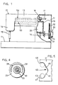
- 10 denotes generally a sewing machine comprising a bed 11, a stand 12 extending upwordly from said bed 11, a bracket arm 13 and a head 14 which is mounted at an end of said arm 13 and from which the needle bar 15 extends.
- a vertical shaft 16 is coupled to the main shaft 17 of the sewing machine and rotated by the latter via a pair of gears 18.
- a bridge support 19 is freely mounted on the shaft 16 and a cam steack 20 is also mounted on said shaft within said support, free to follow the latter in its movements along the axis of said shaft but fixedly connected to said shaft in rotation about its own axis.
- the connection vertical shaft 16 - bridge support 19 - cam stack 20 is not described in detail as it is known in the art.
- the bridge support 19 provided for positioning the stack 20 has a rack 21 which is constantly engaged with a gear 22 mounted on a hollow shaft 26 enclosed in the automatic device 23 according to the present invention.
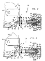
- Said device 23 (Figs. 2 and 3) comprises a selector knob 24 extending from the stand 12 and manipulated by the operator for selecting the cam corresponding to the desired pattern.
- Said knob has a reduced collar 41 on which two radially opposed grooves are formed, each comprising two inclined edges 45 and 46 forming a prostrate V and two edges 47 and 48 parallel to the axis of the selector knob 24 (Fig. 5).
- Said grooves 42 are engaged by pins 43 fixed to an element 33, in the shape of a prostrate U fixed in turn to a first bush 32.
- the free ends 35 of the prostrate U shaped element 33 are adapted to run in seats 36 in a toothed pulley 37 when the selector knob 24 is rotated.
- Said pulley 37 is fixedly connected to the hollow shaft 26 carrying tire gear 22.
- a disk 27 is mounted on which holes 28 are formed which ire circumferentially equidistant (Fig. 4) and the function of which will be explained hereinafter.
- a second bush 29 is inserted into the hollow shaft 26, the toothed pulley 37 and the hub 25 of the selector knob 24. Inside said second bush 29 a shaft 30 extends, an end of which is in contact with the ends of a screw 31, partially screwed onto the first bush 32, which is adapted to run in the second bush 29 as will be explained hereinafter. The axial adjustment of the screw 31 determines the position of the other end of the shaft 30 which projects from the second bush 29.
- selector knob 24 When the operator desires to select a predetermined pattern he operates the selector knob 24 causing it to rotate clockwise or anticlockwise in order to displace the cam stack vertically until the cam for executing the selected pattern is positioned in correspondence with a cam follower 44 which transmits the transversal oscillations to the needle bar 15 in a manner known per se.
- the toothed pulley 37 via a belt 52, displaces an indicator 53 (Fig. 1) which runs along a plate 54 in order to indicate which cam, corresponding to the pattern of said plate 54, is in correspondence with the cam follower 44.
Landscapes
- Engineering & Computer Science (AREA)
- Textile Engineering (AREA)
- Sewing Machines And Sewing (AREA)
- Transmission Devices (AREA)
Applications Claiming Priority (2)
| Application Number | Priority Date | Filing Date | Title |
|---|---|---|---|
| IT4290686 | 1986-03-12 | ||
| IT42906/86A IT1191515B (it) | 1986-03-12 | 1986-03-12 | Dispositivo automatico di stacco dei puntali in una macchina per cucire |
Publications (3)
| Publication Number | Publication Date |
|---|---|
| EP0236927A2 EP0236927A2 (en) | 1987-09-16 |
| EP0236927A3 EP0236927A3 (en) | 1988-02-24 |
| EP0236927B1 true EP0236927B1 (en) | 1991-06-12 |
Family
ID=11254579
Family Applications (1)
| Application Number | Title | Priority Date | Filing Date |
|---|---|---|---|
| EP87103071A Expired EP0236927B1 (en) | 1986-03-12 | 1987-03-04 | Automatic device for detaching the cam followers in a sewing machine |
Country Status (8)
| Country | Link |
|---|---|
| US (1) | US4765268A (it) |
| EP (1) | EP0236927B1 (it) |
| JP (1) | JPS62221387A (it) |
| CN (1) | CN1009563B (it) |
| DE (1) | DE3770659D1 (it) |
| ES (1) | ES2020902B3 (it) |
| IT (1) | IT1191515B (it) |
| YU (1) | YU46852B (it) |
Families Citing this family (1)
| Publication number | Priority date | Publication date | Assignee | Title |
|---|---|---|---|---|
| JP7338946B2 (ja) * | 2017-07-25 | 2023-09-05 | Juki株式会社 | ミシン |
Family Cites Families (7)
| Publication number | Priority date | Publication date | Assignee | Title |
|---|---|---|---|---|
| BE548219A (it) * | 1955-10-29 | |||
| BE568885A (it) * | 1957-06-26 | |||
| GB938417A (en) * | 1962-06-26 | 1963-10-02 | Husqvarna Vapenfabriks Ab | Improvements in or relating to sewing machines |
| IT717653A (it) * | 1964-03-20 | |||
| CH445276A (fr) * | 1965-11-08 | 1967-10-15 | Mefina Sa | Machine à coudre |
| CH535859A (it) * | 1971-02-06 | 1973-04-15 | Necchi Spa | Dispositivo per l'esecuzione automatica di punti ornamentali in macchine per cucire |
| US3786769A (en) * | 1973-02-05 | 1974-01-22 | Singer Co | Pattern selection system |
-
1986
- 1986-03-12 IT IT42906/86A patent/IT1191515B/it active
-
1987
- 1987-01-16 US US07/003,818 patent/US4765268A/en not_active Expired - Fee Related
- 1987-03-04 DE DE8787103071T patent/DE3770659D1/de not_active Expired - Fee Related
- 1987-03-04 ES ES87103071T patent/ES2020902B3/es not_active Expired - Lifetime
- 1987-03-04 EP EP87103071A patent/EP0236927B1/en not_active Expired
- 1987-03-11 JP JP62054288A patent/JPS62221387A/ja active Pending
- 1987-03-11 CN CN87102650A patent/CN1009563B/zh not_active Expired
- 1987-03-12 YU YU41087A patent/YU46852B/sh unknown
Also Published As
| Publication number | Publication date |
|---|---|
| YU46852B (sh) | 1994-06-24 |
| CN1009563B (zh) | 1990-09-12 |
| JPS62221387A (ja) | 1987-09-29 |
| US4765268A (en) | 1988-08-23 |
| IT8642906A1 (it) | 1987-09-12 |
| IT8642906A0 (it) | 1986-03-12 |
| ES2020902A4 (es) | 1991-10-16 |
| IT1191515B (it) | 1988-03-23 |
| YU41087A (en) | 1989-12-31 |
| ES2020902B3 (es) | 1991-12-01 |
| CN87102650A (zh) | 1987-12-30 |
| EP0236927A2 (en) | 1987-09-16 |
| EP0236927A3 (en) | 1988-02-24 |
| DE3770659D1 (de) | 1991-07-18 |
Similar Documents
| Publication | Publication Date | Title |
|---|---|---|
| US2854935A (en) | Automatic shifting mechanism for sewing machines adapted for embroidery work | |
| US4301756A (en) | Device for the interruption of the embroidery needle movement on embroidery- or sewing machines | |
| US5477795A (en) | Thread trimming device for a lockstitch bar tacking sewing machine | |
| EP0236927B1 (en) | Automatic device for detaching the cam followers in a sewing machine | |
| GB2121838A (en) | Device for selecting the dial needles of circular knitting machines | |
| CA1192757A (en) | Coupling arrangement usable in a textile machine | |
| US3043252A (en) | Zigzag sewing machine with fancystitch selector | |
| US2983531A (en) | Means for automatic locking and releasing rechangeable work guiding cams in zig-zag sewing-machines | |
| US4546717A (en) | Sewing machine differential feed | |
| US4408553A (en) | Low torque direct dialing pattern selection mechanism | |
| CS202191B1 (en) | Buttonhole sewing machine | |
| US3009429A (en) | Accessories for facilitating the making of button-holes, particularly by means of a sewing-machine | |
| US4721049A (en) | Selecting mechanism of a double-function sewing machine | |
| GB2085116A (en) | Displacement and detent mechanisms for a multi-head embroidery machine | |
| JPH0238582Y2 (it) | ||
| US2999471A (en) | Adjustable guiding cam mechanism | |
| US3003442A (en) | Stitch selector means for automatic zigzag machines | |
| US4233826A (en) | Control device for striper units in circular knitting machines | |
| JPH05247801A (ja) | ソックス、ストッキングなどを製造する単一シリンダ丸形編成機 | |
| US2981085A (en) | Loose course attachment for knitting machines | |
| EP0247976B1 (en) | Motor vehicle gearbox | |
| JPS6040536B2 (ja) | 回転ドビ−機におけるキ−継手の制御装置 | |
| US4144726A (en) | Wiper control mechanism for a circular knitting machine | |
| US3053206A (en) | Sewing machines having ornamental stitch devices | |
| JPH033138Y2 (it) |
Legal Events
| Date | Code | Title | Description |
|---|---|---|---|
| PUAI | Public reference made under article 153(3) epc to a published international application that has entered the european phase |
Free format text: ORIGINAL CODE: 0009012 |
|
| AK | Designated contracting states |
Kind code of ref document: A2 Designated state(s): CH DE ES FR GB LI SE |
|
| PUAL | Search report despatched |
Free format text: ORIGINAL CODE: 0009013 |
|
| AK | Designated contracting states |
Kind code of ref document: A3 Designated state(s): CH DE ES FR GB LI SE |
|
| 17P | Request for examination filed |
Effective date: 19880526 |
|
| 17Q | First examination report despatched |
Effective date: 19891220 |
|
| GRAA | (expected) grant |
Free format text: ORIGINAL CODE: 0009210 |
|
| AK | Designated contracting states |
Kind code of ref document: B1 Designated state(s): CH DE ES FR GB LI SE |
|
| REF | Corresponds to: |
Ref document number: 3770659 Country of ref document: DE Date of ref document: 19910718 |
|
| RAP2 | Party data changed (patent owner data changed or rights of a patent transferred) |
Owner name: NECCHI MACCHINE PER CUCIRE S.R.L. |
|
| REG | Reference to a national code |
Ref country code: CH Ref legal event code: PUE Owner name: NECCHI MACCHINE PER CUCIRE S.R.L. |
|
| ET | Fr: translation filed | ||
| PLBE | No opposition filed within time limit |
Free format text: ORIGINAL CODE: 0009261 |
|
| STAA | Information on the status of an ep patent application or granted ep patent |
Free format text: STATUS: NO OPPOSITION FILED WITHIN TIME LIMIT |
|
| 26N | No opposition filed | ||
| PGFP | Annual fee paid to national office [announced via postgrant information from national office to epo] |
Ref country code: GB Payment date: 19920618 Year of fee payment: 6 |
|
| PGFP | Annual fee paid to national office [announced via postgrant information from national office to epo] |
Ref country code: FR Payment date: 19930226 Year of fee payment: 7 |
|
| PG25 | Lapsed in a contracting state [announced via postgrant information from national office to epo] |
Ref country code: GB Effective date: 19930304 |
|
| PGFP | Annual fee paid to national office [announced via postgrant information from national office to epo] |
Ref country code: SE Payment date: 19930304 Year of fee payment: 7 |
|
| PGFP | Annual fee paid to national office [announced via postgrant information from national office to epo] |
Ref country code: ES Payment date: 19930311 Year of fee payment: 7 |
|
| PGFP | Annual fee paid to national office [announced via postgrant information from national office to epo] |
Ref country code: CH Payment date: 19930331 Year of fee payment: 7 |
|
| PGFP | Annual fee paid to national office [announced via postgrant information from national office to epo] |
Ref country code: DE Payment date: 19930601 Year of fee payment: 7 |
|
| GBPC | Gb: european patent ceased through non-payment of renewal fee |
Effective date: 19930304 |
|
| PG25 | Lapsed in a contracting state [announced via postgrant information from national office to epo] |
Ref country code: ES Free format text: LAPSE BECAUSE OF NON-PAYMENT OF DUE FEES Effective date: 19940305 Ref country code: SE Free format text: LAPSE BECAUSE OF NON-PAYMENT OF DUE FEES Effective date: 19940305 |
|
| PG25 | Lapsed in a contracting state [announced via postgrant information from national office to epo] |
Ref country code: LI Effective date: 19940331 Ref country code: CH Effective date: 19940331 |
|
| PG25 | Lapsed in a contracting state [announced via postgrant information from national office to epo] |
Ref country code: FR Effective date: 19941130 |
|
| REG | Reference to a national code |
Ref country code: CH Ref legal event code: PL |
|
| PG25 | Lapsed in a contracting state [announced via postgrant information from national office to epo] |
Ref country code: DE Effective date: 19941201 |
|
| REG | Reference to a national code |
Ref country code: FR Ref legal event code: ST |
|
| EUG | Se: european patent has lapsed |
Ref document number: 87103071.4 Effective date: 19941010 |
|
| REG | Reference to a national code |
Ref country code: ES Ref legal event code: FD2A Effective date: 19990503 |