EP0236802A2 - Iron ore melt reduction process - Google Patents
Iron ore melt reduction process Download PDFInfo
- Publication number
- EP0236802A2 EP0236802A2 EP87102235A EP87102235A EP0236802A2 EP 0236802 A2 EP0236802 A2 EP 0236802A2 EP 87102235 A EP87102235 A EP 87102235A EP 87102235 A EP87102235 A EP 87102235A EP 0236802 A2 EP0236802 A2 EP 0236802A2
- Authority
- EP
- European Patent Office
- Prior art keywords
- reaction
- post
- afterburning
- combustion
- gas
- Prior art date
- Legal status (The legal status is an assumption and is not a legal conclusion. Google has not performed a legal analysis and makes no representation as to the accuracy of the status listed.)
- Granted
Links
- XEEYBQQBJWHFJM-UHFFFAOYSA-N Iron Chemical compound [Fe] XEEYBQQBJWHFJM-UHFFFAOYSA-N 0.000 title claims abstract description 49
- 229910052742 iron Inorganic materials 0.000 title claims abstract description 24
- 238000011946 reduction process Methods 0.000 title 1
- 239000007789 gas Substances 0.000 claims abstract description 75
- 238000006243 chemical reaction Methods 0.000 claims abstract description 70
- 238000000034 method Methods 0.000 claims abstract description 38
- UQSXHKLRYXJYBZ-UHFFFAOYSA-N Iron oxide Chemical compound [Fe]=O UQSXHKLRYXJYBZ-UHFFFAOYSA-N 0.000 claims abstract description 15
- QVGXLLKOCUKJST-UHFFFAOYSA-N atomic oxygen Chemical compound [O] QVGXLLKOCUKJST-UHFFFAOYSA-N 0.000 claims abstract description 14
- 239000000155 melt Substances 0.000 claims abstract description 14
- 239000001301 oxygen Substances 0.000 claims abstract description 14
- 229910052760 oxygen Inorganic materials 0.000 claims abstract description 14
- 239000000446 fuel Substances 0.000 claims abstract description 9
- 239000007788 liquid Substances 0.000 claims abstract description 9
- 238000002844 melting Methods 0.000 claims description 17
- 230000008018 melting Effects 0.000 claims description 17
- 238000002485 combustion reaction Methods 0.000 claims description 15
- 238000003723 Smelting Methods 0.000 claims description 11
- OKTJSMMVPCPJKN-UHFFFAOYSA-N Carbon Chemical compound [C] OKTJSMMVPCPJKN-UHFFFAOYSA-N 0.000 claims description 8
- 229910052799 carbon Inorganic materials 0.000 claims description 8
- 239000007791 liquid phase Substances 0.000 claims description 6
- 241001062472 Stokellia anisodon Species 0.000 claims 1
- 239000012495 reaction gas Substances 0.000 claims 1
- 239000000567 combustion gas Substances 0.000 description 17
- 239000003245 coal Substances 0.000 description 10
- 239000000126 substance Substances 0.000 description 5
- 235000019738 Limestone Nutrition 0.000 description 4
- 238000001816 cooling Methods 0.000 description 4
- 239000006028 limestone Substances 0.000 description 4
- VNWKTOKETHGBQD-UHFFFAOYSA-N methane Chemical compound C VNWKTOKETHGBQD-UHFFFAOYSA-N 0.000 description 4
- 238000001465 metallisation Methods 0.000 description 3
- 239000012071 phase Substances 0.000 description 3
- 239000002893 slag Substances 0.000 description 3
- 235000008733 Citrus aurantifolia Nutrition 0.000 description 2
- 235000011941 Tilia x europaea Nutrition 0.000 description 2
- 239000003638 chemical reducing agent Substances 0.000 description 2
- 239000003034 coal gas Substances 0.000 description 2
- 239000004571 lime Substances 0.000 description 2
- 239000000203 mixture Substances 0.000 description 2
- 239000003345 natural gas Substances 0.000 description 2
- 230000003647 oxidation Effects 0.000 description 2
- 238000007254 oxidation reaction Methods 0.000 description 2
- 230000001603 reducing effect Effects 0.000 description 2
- 238000009827 uniform distribution Methods 0.000 description 2
- 238000007664 blowing Methods 0.000 description 1
- 239000002817 coal dust Substances 0.000 description 1
- 239000000470 constituent Substances 0.000 description 1
- -1 dust-like coal Chemical compound 0.000 description 1
- 238000005265 energy consumption Methods 0.000 description 1
- 230000002349 favourable effect Effects 0.000 description 1
- 239000011261 inert gas Substances 0.000 description 1
- 238000004519 manufacturing process Methods 0.000 description 1
- 239000002184 metal Substances 0.000 description 1
- 229910052751 metal Inorganic materials 0.000 description 1
- 238000013021 overheating Methods 0.000 description 1
- 238000010926 purge Methods 0.000 description 1
- 239000000376 reactant Substances 0.000 description 1
- 239000011819 refractory material Substances 0.000 description 1
- 239000007787 solid Substances 0.000 description 1
- 239000008247 solid mixture Substances 0.000 description 1
- 230000008093 supporting effect Effects 0.000 description 1
- 238000011144 upstream manufacturing Methods 0.000 description 1
- 239000002918 waste heat Substances 0.000 description 1
Images

Classifications
-
- C—CHEMISTRY; METALLURGY
- C21—METALLURGY OF IRON
- C21B—MANUFACTURE OF IRON OR STEEL
- C21B11/00—Making pig-iron other than in blast furnaces
-
- C—CHEMISTRY; METALLURGY
- C21—METALLURGY OF IRON
- C21B—MANUFACTURE OF IRON OR STEEL
- C21B13/00—Making spongy iron or liquid steel, by direct processes
- C21B13/14—Multi-stage processes processes carried out in different vessels or furnaces
-
- C—CHEMISTRY; METALLURGY
- C21—METALLURGY OF IRON
- C21B—MANUFACTURE OF IRON OR STEEL
- C21B13/00—Making spongy iron or liquid steel, by direct processes
-
- C—CHEMISTRY; METALLURGY
- C21—METALLURGY OF IRON
- C21B—MANUFACTURE OF IRON OR STEEL
- C21B13/00—Making spongy iron or liquid steel, by direct processes
- C21B13/0006—Making spongy iron or liquid steel, by direct processes obtaining iron or steel in a molten state
- C21B13/0013—Making spongy iron or liquid steel, by direct processes obtaining iron or steel in a molten state introduction of iron oxide into a bath of molten iron containing a carbon reductant
-
- Y—GENERAL TAGGING OF NEW TECHNOLOGICAL DEVELOPMENTS; GENERAL TAGGING OF CROSS-SECTIONAL TECHNOLOGIES SPANNING OVER SEVERAL SECTIONS OF THE IPC; TECHNICAL SUBJECTS COVERED BY FORMER USPC CROSS-REFERENCE ART COLLECTIONS [XRACs] AND DIGESTS
- Y02—TECHNOLOGIES OR APPLICATIONS FOR MITIGATION OR ADAPTATION AGAINST CLIMATE CHANGE
- Y02P—CLIMATE CHANGE MITIGATION TECHNOLOGIES IN THE PRODUCTION OR PROCESSING OF GOODS
- Y02P10/00—Technologies related to metal processing
- Y02P10/10—Reduction of greenhouse gas [GHG] emissions
- Y02P10/122—Reduction of greenhouse gas [GHG] emissions by capturing or storing CO2
-
- Y—GENERAL TAGGING OF NEW TECHNOLOGICAL DEVELOPMENTS; GENERAL TAGGING OF CROSS-SECTIONAL TECHNOLOGIES SPANNING OVER SEVERAL SECTIONS OF THE IPC; TECHNICAL SUBJECTS COVERED BY FORMER USPC CROSS-REFERENCE ART COLLECTIONS [XRACs] AND DIGESTS
- Y02—TECHNOLOGIES OR APPLICATIONS FOR MITIGATION OR ADAPTATION AGAINST CLIMATE CHANGE
- Y02P—CLIMATE CHANGE MITIGATION TECHNOLOGIES IN THE PRODUCTION OR PROCESSING OF GOODS
- Y02P10/00—Technologies related to metal processing
- Y02P10/10—Reduction of greenhouse gas [GHG] emissions
- Y02P10/134—Reduction of greenhouse gas [GHG] emissions by avoiding CO2, e.g. using hydrogen
Definitions
- the invention relates to a process for the smelting reduction of iron ores, in which the iron oxide is reduced substantially in the liquid state and the energy required to compensate for the heat balance of the process by adding carbon-containing fuels to the melt and by post-combustion of the resulting reaction gases, mainly CO and H2, is generated.
- German Offenlegungsschrift 31 33 575 improves the heat supply in the meltdown vessel in that reaction gases from the iron melt are sucked in by oxygen blown onto the bath surface in the space above the melt, carried away to the bath surface, partially burned and the heat generated is transferred to the iron melt.
- liquid iron is produced by adding ore to the iron bath reactor.
- the simultaneously formed Coal gas can be used to pre-reduce ore.
- the fuel consumption in this process is relatively high.
- German patent specification 28 43 303 also has the same disadvantage.
- lumpy coal is placed in a fluidized bed located on the iron bath and the gases are used to pre-reduce iron ore.
- the gases are used to pre-reduce iron ore.
- approximately 900 kg of high-quality coal are required.
- this process produces a considerable excess of gas, the usability of which essentially determines the economics of the process.
- German Offenlegungsschrift 34 18 085 describes a process for iron production from ore, in which the ore is reduced to a degree of metallization of approximately 50% in a ore reduction vessel with the reaction gases from the melting vessel. In this process, 30 to 40% of the reaction gases emerging from the iron melt are afterburned in the melting vessel, and the heat generated is largely transferred to the melt. The reaction gases are then, on the way from the smelting unit to the ore reduction vessel, by adding reducing agents, e.g. Natural gas or dusty coal, reduced and cooled at the same time.
- reducing agents e.g. Natural gas or dusty coal
- Another known method uses largely pre-reduced iron ore with a degree of metallization of 92 to 94%, which is melted together with carbon-containing, solid energy sources and oxygen in the smelting vessel. The resulting gas is used for the pre-reduction of the ores and, to make better use of it, it is circulated and the CO z components removed.
- the object of the present invention is to provide a method which uses a smaller proportion of external energy, e.g. carbon-containing fuels.
- the method according to the invention achieves this object in that the reaction gases are subsequently burned twice or more in succession in oxygen-containing gas jets which blow into reaction spaces which are functionally independent of one another.
- the reaction gases are post-burned at least a second time by sucking the gases back into an oxygen-containing combustion gas after the first post-combustion stage, and the resulting energy is used to a substantial extent in the smelting reduction, for example to melt the introduced, ground ores , with a pre-reduction of the iron ore up to the wustite level.
- An advantageous embodiment of the present invention is that there are fewer reducing conditions at the point of impact of the second post-combustion gas jet than at the point of impact of the first post-combustion gas jet.
- the reduction potential here should be lower compared to the point of impact of the first post-combustion gas jet, since the gas jets generally have a high degree of oxidation and probably react with the liquid phase in the melting vessel.
- the reaction spaces in which the gas jets act can consist of two separate, but directly coupled, vessels.
- the first reaction vessel can be a drum converter which is connected to the second reaction vessel, for example a melting cyclone.
- the reaction spaces of the afterburning gas jets can also be kept separate in a single vessel so that a two-stage afterburning of the reaction gases is possible. Afterburning the reaction gases consecutively two or more times in oxygen-containing gas jets blowing in reaction spaces which are functionally independent of one another is an essential feature of the present invention.
- the bath movement at the point of impact of the first post-combustion gas jet can be set to be significantly greater due to the amount and type of the reactants or purge gases introduced than at the point of impact of the second or further post-combustion gas jet.
- the first post-combustion gas jet hits the surface of the iron bath in an area where mainly metallic splashes occur.
- the second post-combustion gas jet on the other hand, largely comes along the slag in contact with the melt, which has hardly any reducing effect on the almost completely burned gas.
- the ground ore can be added partially or completely in the second reaction space.
- the liquid phase i.e. in the melt, there should be sufficient concentration and mass exchange between the two reaction spaces.
- the vigorous bath movement in reaction room 1 is normally sufficient for this.
- the energy sources mainly the carbon-containing fuels
- the addition of the oxidized substances, such as the ore to be reduced, advantageously takes place in the reaction space 2, in which the second post-combustion gas jet acts.
- the afterburning gas jets can be arranged differently in their reaction spaces.
- the nozzle diameter and the travel distance of the gas are of crucial importance.
- an oblique arrangement is advisable.
- the primary and secondary post-combustion gas jets can be aligned in parallel, but also an opposite inclination, based on the melting reactor geometry, can result in better conditions for the afterburning.
- the use of preheated air i.e. Hot wind
- the hot wind can be replaced at times and / or in certain areas by oxygen or any mixtures of oxygen and preheated air.
- a cross-exchange of the substances in the liquid phase between the two reaction spaces is advantageous because, for example, this also involves balancing the energy between the reaction spaces.
- this is Cross exchange in the liquid phase is not absolutely necessary.
- the process can also be carried out by melting the iron oxide in a coupled second reaction vessel, which is separated from the first system in its liquid region, whereby it can thermally decompose to wustite, and then feeding this melt to the reaction space.
- the ore is blown in in fine-grained form together with the second post-combustion gas jet, it can make sense to improve the heat utilization by introducing the ore into the post-combustion gas jet in such a way that it is simultaneously heated.
- a grain size of up to 0.3 mm and a good, uniform distribution of the ground ores within the post-combustion gas jet have proven successful.
- the uniform distribution of the fine ore can be achieved if it is blown in at the lowest possible speed of approx. 50 to 200 m / sec in order to promote swirling in the gas jet at the point of introduction.
- the drum-shaped melting reactor 1 is rotatable about its axis of symmetry.
- the hot wind is fed via line 2 to the two wind forms 3 and 4.
- the afterburning gas jets are directed from above onto the bath surface.
- a first reaction space is created below the inflation opening 3 and the second reaction space below the inflation opening 4.
- the fuels containing carbon mainly dust-like coal, are fed to the melt through the nozzles 5.
- Other types of coal addition, for example by inflation, are also possible.
- the ground ore is blown in via the feed line 6 together with the second post-combustion gas jet via the opening 4.
- the gas flow in the melting reactor 1 is represented by arrows.
- the two reaction spaces are functionally independent of one another, i.e. essentially separated in the gas phase because the inflation jets show a high stability.
- FIG. 3 A variant of the method according to the invention with a melting reactor 10, the first reaction chamber and a coupled second reaction chamber 11 is shown in FIG. 3.
- the liquid phase is also in two separate reaction spaces.
- the exhaust gases from the first reaction chamber 10 pass through the opening 12 into a water-cooled second reaction chamber 11.
- the exhaust gases from the melting reactor 10 are burned by the two afterburning gas jets from the nozzles 13.
- the ore which is fed to the nozzles 13 through the feed line 6 melted and thermally reduced to Fe0.
- the molten wustite runs via the water-cooled channel 14 into the first reaction space, ie the meltdown reactor.
- the liquid wustite therefore flows to the melt in the first reaction space without coming into contact with the refractory material.
- FIG. 4 shows a further embodiment of the present invention.
- the exhaust gases from the smelting reactor 1 flow through the rotating union 15 and are cooled in the directly following cooling chamber 16 by the addition of limestone via the feed 17 and fine ore via the feed 18.
- these powdery substances absorb the metal droplets contained in the exhaust gas.
- limestone and ore are successively fed in to cool the gases.
- the limestone is deacidified quickly at high temperatures and the ore is then heated.
- the powdery substances are separated hot in a cyclone 19, and if necessary the gas-solid mixture can be cooled further beforehand. For this purpose, it has proven useful to add recirculated exhaust gas upstream of the cyclone 19.
- the mixture of preheated ore (approx. 700 ° C) and lime is then conveyed from the cyclone 19 via line 20 into the afterburning gas jet of the inflator 4. From the melting reactor, a partial stream of the exhaust gases can be fed directly to a waste heat boiler via line 21, and this portion of exhaust gas can be used, for example, to generate hot wind.
- Another example to explain the present invention relates to a particularly simple method variant.
- the exhaust gas passes the second reaction chamber on its way to the gas outlet of the melting reactor.
- this reaction chamber 2 you blow with a similar inflation technique as in reaction chamber 1, hot wind on the bath.
- the hot wind is loaded with fine-grain ore, which heats up in contact with the hot wind.
- the addition of ore and the inflated, preheated air result in a significantly increased iron oxide content in the slag compared to reaction chamber 1 in the area of the bath surface in this second reaction chamber.
- the degree of afterburning achieved in reaction chamber 2 is approximately 80%, and from this amount of heat, similarly as in reaction chamber 1, approximately 90% is transferred to the bath.
Landscapes
- Engineering & Computer Science (AREA)
- Chemical & Material Sciences (AREA)
- Manufacturing & Machinery (AREA)
- Materials Engineering (AREA)
- Metallurgy (AREA)
- Organic Chemistry (AREA)
- Manufacture Of Iron (AREA)
- Manufacture And Refinement Of Metals (AREA)
- Gears, Cams (AREA)
- Nozzles For Spraying Of Liquid Fuel (AREA)
- Furnace Details (AREA)
Abstract
Description
Die Erfindung betrifft ein Verfahren zur Schmelzreduktion von Eisenerzen, bei dem das Eisenoxid im wesentlichen im flüssigen Zustand reduziert wird und die erforderliche Energie zum Ausgleich der Wärmebilanz des Prozesses durch die Zugabe kohlenstoffenthaltender Brennstoffe an die Schmelze und durch die Nachverbrennung der entstehenden Reaktionsgase, hauptsächlich CO und H2, erzeugt wird.The invention relates to a process for the smelting reduction of iron ores, in which the iron oxide is reduced substantially in the liquid state and the energy required to compensate for the heat balance of the process by adding carbon-containing fuels to the melt and by post-combustion of the resulting reaction gases, mainly CO and H2, is generated.
Es sind bereits eine Reihe von Verfahren bekannt, bei denen vorreduziertes Erz zusammen mit Kohle eingeschmolzen und das dabei entstehende Gas für die Reduktion von Eisenerz genutzt wird.A number of processes are already known in which pre-reduced ore is smelted together with coal and the resulting gas is used for the reduction of iron ore.
Der Prozeß gemäß der deutschen Offenlegungsschrift 31 33 575 verbessert das Wärmeangebot im Einschmelzgefäß dadurch, daß Reaktionsgase aus der Eisenschmelze durch auf die Badoberfläche geblasenen Sauerstoff im Raum oberhalb der Schmelze angesaugt, zur Badoberfläche mitgerissen, teilweise verbrannt und die entstehende Wärme an die Eisenschmelze übertragen wird. Bei diesem bekannten Verfahren erzeugt man flüssiges Eisen durch die Erzzugabe in den Eisenbadreaktor. Das gleichzeitig gebildete Kohlegas läßt sich zur Vorreduktion von Erz nutzen. Der Brennstoffverbrauch bei diesem Verfahren ist allerdings relativ hoch.The process according to German Offenlegungsschrift 31 33 575 improves the heat supply in the meltdown vessel in that reaction gases from the iron melt are sucked in by oxygen blown onto the bath surface in the space above the melt, carried away to the bath surface, partially burned and the heat generated is transferred to the iron melt. In this known process, liquid iron is produced by adding ore to the iron bath reactor. The simultaneously formed Coal gas can be used to pre-reduce ore. However, the fuel consumption in this process is relatively high.
Mit dem gleichen Nachteil ist auch der Prozeß gemäß der deutschen Patentschrift 28 43 303 behaftet. Bei diesem Verfahren wird stückige Kohle in ein Wirbelbett, das sich auf dem Eisenbad befindet, gegeben, und die Gase dienen zur Vorreduktion von Eisenerz. Um 1 t flüssiges Eisen aus dem in der Gasphase auf einen hohen Metallisierungsgrad vorreduzierten Erz zu erzeugen, benötigt man ca. 900 kg einer hochwertigen Kohle. Dieses Verfahren produziert aber einen beträchtlichen Gasüberschuß, dessen Verwertbarkeit im wesentlichen die Wirtschaftlichkeit des Prozesses bestimmt.The process according to German patent specification 28 43 303 also has the same disadvantage. In this process, lumpy coal is placed in a fluidized bed located on the iron bath and the gases are used to pre-reduce iron ore. In order to produce 1 t of liquid iron from the ore, which was reduced to a high degree of metallization in the gas phase, approximately 900 kg of high-quality coal are required. However, this process produces a considerable excess of gas, the usability of which essentially determines the economics of the process.
Die deutsche Offenlegungsschrift 34 18 085 beschreibt ein Verfahren zur Eisenherstellung aus Erz, bei dem man in einem Erzreduktionsgefäß mit den Reaktionsgasen aus dem Einschmelzgefäß das Erz auf einen Metallisierungsgrad von ca. 50 % reduziert. Bei diesem Prozeß werden die aus der Eisenschmelze austretenden Reaktionsgase im Einschmelzgefäß zu 30 bis 40 % nachverbrannt, und die entstehende Wärme wird dabei weitgehend an die Schmelze übertragen. Die Reaktionsgase werden dann, auf dem Weg vom Einschmelzaggregat zum Erzreduktionsgefäß, durch Zugabe von Reduktionsmitteln, wie z.B. Erdgas oder staubförmige Kohle, reduziert und gleichzeitig abgekühlt.German Offenlegungsschrift 34 18 085 describes a process for iron production from ore, in which the ore is reduced to a degree of metallization of approximately 50% in a ore reduction vessel with the reaction gases from the melting vessel. In this process, 30 to 40% of the reaction gases emerging from the iron melt are afterburned in the melting vessel, and the heat generated is largely transferred to the melt. The reaction gases are then, on the way from the smelting unit to the ore reduction vessel, by adding reducing agents, e.g. Natural gas or dusty coal, reduced and cooled at the same time.
Ein anderes, bekanntes Verfahren verwendet weitgehend vorreduziertes Eisenerz mit einem Metallisierungsgrad von 92 bis 94 %, das zusammen mit kohlenstoffhaltigen, festen Energieträgern und Sauerstoff im Einschmelzgefäß aufgeschmolzen wird. Das entstehende Gas dient zur Vorreduktion der Erze und, um es dabei besser auszunutzen, führt man es im Kreislauf und entfernt die COz-Anteile.Another known method uses largely pre-reduced iron ore with a degree of metallization of 92 to 94%, which is melted together with carbon-containing, solid energy sources and oxygen in the smelting vessel. The resulting gas is used for the pre-reduction of the ores and, to make better use of it, it is circulated and the CO z components removed.
Bei den beiden letztgenannten Verfahren kombiniert man somit drei Schritte, um zu einem möglichst niedrigen Brennstoffverbrauch zu gelangen, nämlich einerseits die Schmelzreduktion mit Nachverbrennung, Heißgasreduktion der Abgase aus dem Einschmelzgefäß und Vorreduktion der Erze in der Gasphase oder andererseits Einschmelzen mit Kohle und Sauerstoff ohne Nachverbrennung, Ausnutzung der Gase zur Vorreduktion und Entfernen des COz bei der Gasrückführung. Diese Prozesse benötigen ca. 600 kg Kohle, um 1 t Eisen aus Eisenerz herzustellen.In the latter two methods, three steps are combined in order to achieve the lowest possible fuel consumption, namely on the one hand the smelting reduction with afterburning, hot gas reduction of the exhaust gases from the smelting vessel and pre-reduction of the ores in the gas phase or on the other hand melting with coal and oxygen without afterburning, Utilization of the gases for pre-reduction and removal of the CO z in the gas recirculation. These processes require approximately 600 kg of coal to produce 1 t of iron from iron ore.
Die Aufgabe der vorliegenden Erfindung besteht darin, ein Verfahren zu schaffen, das mit einem geringeren Anteil von Fremdenergie, z.B. kohlenstoffenthaltende Brennstoffe, auskommt.The object of the present invention is to provide a method which uses a smaller proportion of external energy, e.g. carbon-containing fuels.
Das erfindungsgemäße Verfahren löst diese Aufgabe dadurch, daß die Reaktionsgase nacheinander zweimal oder häufiger in sauerstoffenthaltenden Gasstrahlen, die in Reaktionsräume blasen, die wirkungsmäßig unabhängig voneinander sind, nachverbrannt werden.The method according to the invention achieves this object in that the reaction gases are subsequently burned twice or more in succession in oxygen-containing gas jets which blow into reaction spaces which are functionally independent of one another.
Gemäß der Erfindung werden die Reaktionsgase mindestens ein zweites Mal nachverbrannt, indem man die Gase nach der ersten Nachverbrennungsstufe wieder in ein sauerstoffenthaltendes Verbrennungsgas einsaugt, und die dabei entstehende Energie wird zu ihrem wesentlichen Anteil bei der Schmelzreduktion genutzt, beispielsweise zum Schmelzen der eingeleiteten, gemahlenen Erze, wobei auch eine Vorreduktion des Eisenerzes bis zur Wüstit-Stufe erfolgen kann.According to the invention, the reaction gases are post-burned at least a second time by sucking the gases back into an oxygen-containing combustion gas after the first post-combustion stage, and the resulting energy is used to a substantial extent in the smelting reduction, for example to melt the introduced, ground ores , with a pre-reduction of the iron ore up to the wustite level.
Eine vorteilhafte Ausführungsform der vorliegenden Erfindung besteht darin, daß an der Auftreffstette des zweiten Nachverbrennungsgasstrahles weniger reduzierende Bedingungen vorliegen als an der Auftreffstelle des ersten Nachverbrennungsgasstrahles. Um einen hohen Nachverbrennungsgrad in der zweiten Stufe zu erreichen, sollte das Reduktionspotential hier niedriger sein im Vergleich zur Auftreffstelle des ersten Nachverbrennungsgasstrahles, da die Gasstrahlen im allgemeinen einen hohen Oxidationsgrad aufweisen und wahrscheinlich mit der flüssigen Phase im Einschmelzgefäß reagieren.An advantageous embodiment of the present invention is that there are fewer reducing conditions at the point of impact of the second post-combustion gas jet than at the point of impact of the first post-combustion gas jet. Around To achieve a high degree of post-combustion in the second stage, the reduction potential here should be lower compared to the point of impact of the first post-combustion gas jet, since the gas jets generally have a high degree of oxidation and probably react with the liquid phase in the melting vessel.
Gemäß der Erfindung können die Reaktionsräume, in denen die Gasstrahlen wirken, aus zwei getrennten, jedoch unmittelbar aneinander gekoppelte, Gefäßen bestehen. Beispielsweise kann das erste Reaktionsgefäß ein Trommelkonverter sein, der mit dem zweiten Reaktionsgefäß, beispielsweise einem Schmelzzyklon, verbunden ist. Überraschenderweise hat es sich jedoch gezeigt, daß auch in einem einzigen Gefäß sich die Reaktionsräume der Nachverbrennungsgasstrahlen so getrennt halten lassen, daß eine zweistufige Nachverbrennung der Reaktionsgase möglich ist. Die Reaktionsgase nacheinander zweimal oder häufiger in sauerstoffenthaltenden Gasstrahlen, die in Reaktionsräume blasen, die wirkungsmäßig unabhängig voneinander sind, nachzuverbrennen, ist ein wesentliches Merkmal der vorliegenden Erfindung.According to the invention, the reaction spaces in which the gas jets act can consist of two separate, but directly coupled, vessels. For example, the first reaction vessel can be a drum converter which is connected to the second reaction vessel, for example a melting cyclone. Surprisingly, however, it has been found that the reaction spaces of the afterburning gas jets can also be kept separate in a single vessel so that a two-stage afterburning of the reaction gases is possible. Afterburning the reaction gases consecutively two or more times in oxygen-containing gas jets blowing in reaction spaces which are functionally independent of one another is an essential feature of the present invention.
Gemäß der Erfindung wirkt sich die Einhaltung der folgenden Maßnahmen beim Betrieb des Einschmelzreaktors unterstützend auf die betriebssichere Einstellung der zweistufigen Nachverbrennung im gleichen Gefäß und die Erzielung eines hohen Gesamtnachverbrennungsgrades, sowie der sicheren Rückübertragung der erzeugten Wärme an die Schmelze, aus. Die Badbewegung an der Auftreffstelle des ersten Nachverbrennungsgasstrahles, also dem Bereich mit hohem Reduktionspotential, ist durch die Menge und Art der eingeleiteten Reaktionspartner oder Spülgase deutlich größer einzustellen als an der Auftreffstelle des zweiten oder weiterer Nachverbrennungsgasstrahlen. Der erste Nachverbrennungsgasstrahl trifft die Oberfläche des Eisenbades in einem Bereich, in dem hauptsächlich metallische Spritzer auftreten. Der zweite Nachverbrennungsgasstrahl kommt dagegen weitgehend mit der Schlacke auf der Schmelze in Berührung, die kaum noch reduzierend auf das annähernd vollständig verbrannte Gas wirkt.According to the invention, compliance with the following measures during operation of the smelting reactor has a supporting effect on the reliable setting of the two-stage post-combustion in the same vessel and the achievement of a high overall degree of post-combustion, as well as the safe retransfer of the heat generated to the melt. The bath movement at the point of impact of the first post-combustion gas jet, that is to say the area with a high reduction potential, can be set to be significantly greater due to the amount and type of the reactants or purge gases introduced than at the point of impact of the second or further post-combustion gas jet. The first post-combustion gas jet hits the surface of the iron bath in an area where mainly metallic splashes occur. The second post-combustion gas jet, on the other hand, largely comes along the slag in contact with the melt, which has hardly any reducing effect on the almost completely burned gas.
Weiterhin hat es sich als vorteilhaft herausgestellt, die Badtiefe in dem ersten Reaktionsraum, mit höherem Reduktionspotential, größer als im zweiten Reaktionsraum auszulegen. Besonders günstig ist es, wenn in dem zweiten Reaktionsraum praktisch kein Eisenbad mehr vorhanden ist, sondern nur noch flüssige Schlacke.Furthermore, it has proven to be advantageous to design the bath depth in the first reaction chamber, with a higher reduction potential, to be larger than in the second reaction chamber. It is particularly advantageous if there is practically no longer an iron bath in the second reaction chamber, but only liquid slag.
Das aufgemahlene Erz kann erfindungsgemäß teilweise oder vollständig im zweiten Reaktionsraum zugegeben werden. In der flüssigen Phase, d.h. in der Schmelze, sollte zwischen den beiden Reaktionsräumen ein ausreichender Konzentrations- und Stoffaustausch erfolgen. Normalerweise reicht die kräftige Badbewegung im -Reaktionsraum 1 dazu aus.According to the invention, the ground ore can be added partially or completely in the second reaction space. In the liquid phase, i.e. in the melt, there should be sufficient concentration and mass exchange between the two reaction spaces. The vigorous bath movement in reaction room 1 is normally sufficient for this.
Die Energieträger, hauptsächlich die kohlenstoff enthaltenden Brennstoffe, führt man der Schmelze vorteilhafterweise im Bereich des ersten Nachverbrennungsreaktionsraumes zu, in dem die Reaktionsgase dann auch der ersten Nachverbrennung unterliegen. Demgegenüber erfolgt die Zugabe der oxidierten Stoffe, wie das zu reduzierende Erz, vorteilhafterweise im Reaktionsraum 2, in dem der zweite Nachverbrennungsgasstrahl wirkt.The energy sources, mainly the carbon-containing fuels, are advantageously fed to the melt in the region of the first post-combustion reaction space, in which the reaction gases are then also subjected to the first post-combustion. In contrast, the addition of the oxidized substances, such as the ore to be reduced, advantageously takes place in the
Gemäß der Erfindung können die Nachverbrennungsgasstrahlen in ihren Reaktionsräumen unterschiedlich angeordnet werden. Zur Erzielung eines optimalen Nachverbrennungsgrades sind der Düsendurchmesser und die Laufstrecke des Gases von entscheidender Bedeutung. Beispielsweise kann man die Nachverbrennungsgasstrahlen senkrecht auf das Bad richten. Um jedoch eine längere Laufstrecke zu erreichen, ist eine schräge Anordnung zweckmäßig. Der Primär- und Sekundär-Nachverbrennungsgasstrahl kann parallel ausgerichtet sein, jedoch auch eine entgegengesetzte Neigung kann, bezogen auf die Einschmelzreaktorgeometrie, bessere Bedingungen für die Nachverbrennung ergeben.According to the invention, the afterburning gas jets can be arranged differently in their reaction spaces. In order to achieve an optimal degree of afterburning, the nozzle diameter and the travel distance of the gas are of crucial importance. For example, one can direct the post-combustion gas jets perpendicular to the bath. However, to achieve a longer running distance, an oblique arrangement is advisable. The primary and secondary post-combustion gas jets can be aligned in parallel, but also an opposite inclination, based on the melting reactor geometry, can result in better conditions for the afterburning.
Niedrige Verbrauchswerte an Energieträgern und damit eine hohe Wirtschaftlichkeit des Verfahrens, lassen sich erfindungsgemäß durch einen Nachverbrennungsgrad von 30 bis 50 % im ersten Reaktionsraum und von 60 bis 100 % in der zweiten Nachverbrennungsstufe erreichen. Neben den bereits genannten Maßnahmen hat sich zur Erzielung der hohen Nachverbrennungsraten die Anwendung von vorgewärmter Luft, d.h. Heißwind, als sauerstoffenthaltendes Gas bewährt. Überraschenderweise bewirkt die Verwendung von Heißwind als Sauerstoffträger bei dem erfindungsgemäßen Verfahren keine unerwünschte Überhitzung im Gasraum des Einschmelzreaktors. Der Heißwind kann zeit-und/oder bereichsweise durch Sauerstoff oder beliebige Mischungen von Sauerstoff und vorgewärmter Luft ersetzt werden.According to the invention, low energy consumption values and thus a high level of economy of the process can be achieved by a degree of afterburning of 30 to 50% in the first reaction chamber and from 60 to 100% in the second afterburning stage. In addition to the measures already mentioned, the use of preheated air, i.e. Hot wind, proven as an oxygen-containing gas. Surprisingly, the use of hot wind as an oxygen carrier in the process according to the invention does not cause undesired overheating in the gas space of the meltdown reactor. The hot wind can be replaced at times and / or in certain areas by oxygen or any mixtures of oxygen and preheated air.
Es liegt weiterhin im Sinne der vorliegenden Erfindung, das Abgas bei dem oder nach dem Verlassen des Einschmelzreaktors, damit ist auch das erwähnte kombinierte Reaktionsgefäß aus zwei Kammern gemeint, durch Zugabe von Reduktionsmitteln, wie z.B. pulverförmige Kohle oder Erdgas, abzukühlen und gleichzeitig zu reduzieren und somit den Heizwert deutlich anzuheben. Auch ein Teilstrom des Abgases kann in dieser Weise behandelt werden. Bei einer vorteilhaften Ausgestaltung der Erfindung nimmt man einen Teilstrom der Abgase aus dem Reaktionsraum 1 und reduziert ihn in der genannten Art, um mit diesem Gas die Luft für den Prozeß vorzuheizen.It is further within the scope of the present invention to remove the exhaust gas when or after leaving the melting reactor, which also means the mentioned combined reaction vessel from two chambers, by adding reducing agents, e.g. powdered coal or natural gas to cool and reduce at the same time and thus significantly increase the calorific value. A partial flow of the exhaust gas can also be treated in this way. In an advantageous embodiment of the invention, a partial flow of the exhaust gases from the reaction chamber 1 is taken and reduced in the manner mentioned in order to preheat the air for the process with this gas.
Gemäß der Erfindung ist ein Queraustausch der Stoffe in der flüssigen Phase zwischen den beiden Reaktionsräumen vorteilhaft, denn damit ist beispielsweise auch ein Ausgleich der Energie zwischen den Reaktionsräumen verbunden. Allerdings ist bei der Durchführung des Verfahrens gemäß der Erfindung dieser Queraustausch in der flüssigen Phase nicht zwingend erforderlich. Das Verfahren läßt sich auch in der Weise betreiben, daß man in einem angekoppelten zweiten Reaktionsgefäß, das in seinem Flüssigkeitsbereich vom ersten System getrennt ist, das Eisenoxid aufschmilzt, wobei es sich thermisch zu Wüstit zersetzen kann, und dann diese Schmelze dem Reaktionsraum zuführt.According to the invention, a cross-exchange of the substances in the liquid phase between the two reaction spaces is advantageous because, for example, this also involves balancing the energy between the reaction spaces. However, when carrying out the method according to the invention this is Cross exchange in the liquid phase is not absolutely necessary. The process can also be carried out by melting the iron oxide in a coupled second reaction vessel, which is separated from the first system in its liquid region, whereby it can thermally decompose to wustite, and then feeding this melt to the reaction space.
Falls man das Erz feinkörnig zusammen mit dem zweiten Nachverbrennungsgasstrahl einbläst, kann es zur Verbesserung der Wärmeausnutzung sinnvoll sein, das Erz so in den Nachverbrennungsgasstrahl einzuleiten, daß es gleichzeitig mit aufgeheizt wird. Um dies zu erreichen, haben sich eine Korngröße bis 0.3 mm und eine gute gleichmäßige Verteilung der gemahlenen Erze innerhalb des Nachverbrennungsgasstrahls bewährt. Erfindungsgemäß kann man die Gleichverteilung des Feinerzes erreichen, wenn es mit möglichst niedriger Geschwindigkeit von ca. 50 bis 200 m/sek eingeblasen wird, um an der Einleitungsstelle eine Verwirbelung im Gasstrahl zu begünstigen.If the ore is blown in in fine-grained form together with the second post-combustion gas jet, it can make sense to improve the heat utilization by introducing the ore into the post-combustion gas jet in such a way that it is simultaneously heated. To achieve this, a grain size of up to 0.3 mm and a good, uniform distribution of the ground ores within the post-combustion gas jet have proven successful. According to the invention, the uniform distribution of the fine ore can be achieved if it is blown in at the lowest possible speed of approx. 50 to 200 m / sec in order to promote swirling in the gas jet at the point of introduction.
Die Erfindung wird nun anhand von schematischen Darstellungen und nichteinschränkenden beispielhaften Angaben näher erläutert.The invention will now be explained in more detail with the aid of schematic representations and non-restrictive exemplary information.
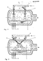
- Figur 1 und Figur 2 zeigen Längsschnitte durch einen trommelförmigen Einschmelzreaktor mit unterschiedlicher Anordnung der Aufblasvorrichtungeri.Figure 1 and Figure 2 show longitudinal sections through a drum-shaped melting reactor with different arrangement of the inflator.
- Figur 3 zeigt den Längsschnitt durch einen Einschmelzreaktor mit einem angekoppelten zweiten Reaktionsgefäß.Figure 3 shows the longitudinal section through a meltdown reactor with a coupled second reaction vessel.
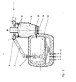
- Figur 4 zeigt den Längsschnitt durch einen trommelförmigen Einschmelzreaktor mit nachgeschalteter Kühlkammer für die Abgase und anschließendem Zyklon.Figure 4 shows the longitudinal section through a drum-shaped melting reactor with a downstream cooling chamber for the exhaust gases and subsequent cyclone.
Der trommelförmige Einschmelzreaktor 1 ist um seine Symmetrieachse drehbar. Der Heißwind wird über Leitung 2 den beiden Windformen 3 und 4 zugeführt. Die Nachverbrennungsgasstrahlen sind von oben auf die Badoberfläche gerichtet. Es entsteht ein erster Reaktionsraum unterhalb der Aufblasöffnung 3 und der zweite Reaktionsraum unterhalb der Aufblasöffnung 4. Die kohtenstoffenthaltenden Brennstoffe, hauptsächlich staubförmige Kohle, werden durch die Düsen 5 der Schmelze zugeführt. Andere Kohlezugabearten, beispielsweise durch Aufblasen, sind ebenfalls möglich. Das gemahlene Erz wird über die Zuführungsleitung 6 zusammen mit dem zweiten Nachverbrennungsgasstrahl Ober die Öffnung 4 eingeblasen. Die Gasströmung im Einschmelzreäktor 1 ist durch Pfeile dargestellt. Wie aus Figur 1 zu entnehmen, sind die beiden Reaktionsräume wirkungsmäßig unabhängig voneinander, d.h. in der Gasphase im wesentlichen getrennt, weil die Aufblasstrahlen eine hohe Stabilität zeigen.The drum-shaped melting reactor 1 is rotatable about its axis of symmetry. The hot wind is fed via
Diese Stabilität der Nachverbrennungsgasstrahlen zusammen mit der Tatsache, daß im oberen Bereich, d.h. in unmittelbarer Nähe der Aufblasöffnung, noch keine großen Gasmengen angesaugt werden, läßt sich dazu nutzen, die beiden Nachverbrennungsgasstrahlen, wie in Figur 2 dargestellt, im oberen Bereich gegeneinander blasen zu lassen. Allerdings müssen die Düsen so angeordnet sein, daß die Gasstrahlen sich im Raum nicht kreuzen.This stability of the afterburning gas jets together with the fact that in the upper region, i.e. in the immediate vicinity of the inflation opening, yet no large amounts of gas are sucked in, can be used to allow the two post-combustion gas jets to be blown against one another in the upper region, as shown in FIG. However, the nozzles must be arranged so that the gas jets do not cross in the room.
Eine Variante des erfindungsgemäßen Verfahrens mit Einschmelzreaktor 10, dem ersten Reaktionsraum und einem angekoppelten zweiten Reaktionsraum 11, ist in Figur 3 dargestellt. In diesem Fall befindet sich auch die flüssige Phase in zwei getrennten Reaktionsräumen. Die Abgase aus dem ersten Reaktionsraum 10 gelangen über die Öffnung 12 in einen wassergekühlten zweiten Reaktionsraum 11. Im Reaktionsraum 11 werden die Abgase aus dem Einschmelzreaktor 10 durch die beiden Nachverbrennungsgasstrahlen aus den Düsen 13 verbrannt. Gleichzeitig wird das Erz, das den Düsen 13 durch die Zuführungsleitung 6 zugeleitet wird, aufgeschmolzen und thermisch zu Fe0 reduziert. Das geschmolzene Wüstit läuft über die wassergekühlte Rinne 14 in den ersten Reaktionsraum, d.h. den Einschmelzreaktor. Das flüssige Wüstit fließt also, ohne mit dem Feuerfest-Material in Kontakt zu kommen, der Schmelze im ersten Reaktionsraum zu.A variant of the method according to the invention with a melting
Die Figur 4 zeigt eine weitere Ausgestaltung der vorliegenden Erfindung. Die Abgase aus dem Einschmelzreaktor 1 durchströmen die Drehdurchführung 15 und werden in der direkt anschließenden Abkühlkammer 16, durch die Zugabe von Kalkstein über die Zuführung 17 und Feinerz über die Zuführung 18 abgekühlt. Dabei nehmen diese pulverförmigen Substanzen gleichzeitig die im Abgas enthaltenen Metalltröpfchen auf. In einer besonders vorteilhaften Ausführungsform der Erfindung führt man Kalkstein und Erz zur Abkühlung der Gase nacheinander zu. Dadurch wird die Entsäuerung des Kalksteins schnell bei hohen Temperaturen durchgeführt und das Erz anschließend aufgeheizt. Die pulverförmigen Stoffe scheidet man nach erfolgter Kühlung heiß in einem Zyklon 19 ab, und ggf. kann das Gas-Feststoff-Gemisch vorher noch weiter abgekühlt werden. Hierfür hat es sich bewährt, rezirkuliertes Abgas vor dem Zyklon 19 zuzugeben. Das Gemisch aus vorgewärmtem Erz (ca. 700°C) und Kalk fördert man dann aus dem Zyklon 19 über die Leitung 20 in den Nachverbrennungsgasstrahl der Aufblaseinrichtung 4. Aus dem Einschmelzreaktor läßt sich ein Teilstrom der Abgase über Leitung 21 direkt einem Abhitzekessel zuführen, und diesen Abgasanteil kann man beispielsweise für die Heißwinderzeugung nutzen.FIG. 4 shows a further embodiment of the present invention. The exhaust gases from the smelting reactor 1 flow through the rotating
In ein Einschmelzgefäß, ähnlich Figur 4, bläst man zur Erzeugung von 1 t Eisen über die Unterbaddüsen 5 550 kg einer Gasflammkohle mit ca. 33 % flüchtigen Bestandteilen und einem Heizwert Hu von 7200 kcal/kg ein. Zur weiteren Unterstützung des Wärmeüberganges aus dem Nachverbrennungsgasstrahl im ersten Reaktionsraum können zusätzlich ca. 5 % der Gesamterzmenge durch die Düsen 5 strömen. Über die Windform 3 werden 1800 m' Heißwind mit einer Vorheiztemperatur von ca. 1200°C aufgeblasen. Im ersten Reaktionsraum läßt sich dann ein Nachverbre-nnungsgrad von 40 % erreichen, d.h. das Abgas, das den Reaktionsraum 1 in Richtung des Gasaustrittes verläßt, hat im Mittel einen Oxidationsgrad von 40 %. Im zweiten Reaktionsraum bläst man durch Windform 4 noch einmal 800 NM 3 Heißwind mit gleicher Temperatur auf und erreicht dadurch einen Nachverbrennungsgrad von insgesamt 80 %. Zusammen mit diesem Nachverbrennungsgasstrahl im zweiten Reaktionsraum werden Erz und Kalk, beides auf ca. 700°C vorgeheizt, mit auf das Bad geblasen. Es entsteht ein Abgasvolumen von 2100 m3 mit einem fühlbaren Wärmeinhalt von 1.3 Gcal und einem chemischen, d.h. gebundenen, Wärmeinhalt von 0.4 Gcal. Dieses Abgas wird unmittelbar nach Passieren der Drehdurchführung 15 durch die Zugabe des Erzes und der gesamten Kalksteinmenge von etwa 300 kg/t Eisen, abgekühlt. Dabei stellt sich eine mittlere Temperatur von ca. 1200°C ein. Zur weiteren Abkühlung auf ca. 800°C führt man direkt vor dem Zyklon ca. 500 Nm3 rezirkuliertes Abgas zu.In a smelting vessel, similar to FIG. 4, 5 550 kg of a gas flame coal with approx. 33% volatile constituents and a calorific value Hu of 7200 kcal / kg are blown in via the lower bath nozzles in order to produce 1 t of iron. To further support the heat transfer from the afterburning gas jet in the first Approx. 5% of the total amount of ore can flow through the
Ein weiteres Beispiel zur Erläuterung der vorliegenden Erfindung betrifft eine besonders einfache Verfahrensvariante.Another example to explain the present invention relates to a particularly simple method variant.
In einem langgestreckten, trommelförmigen Einschmelzreaktor mit den äußeren Abmessungen von ca. 10 m Länge und 6 m Durchmesser und einer 60 cm starken feuerfesten Zustellung werden pro Stunde ca. 50 t flüssiges Eisen erzeugt. In der ersten Reaktionszone führt man dem Eisenbad vorzugsweise durch die Unterbaddüsen ca. 600 kg/t Eisen einer Gasflammkohle zu. Die gesamte, für die Verbrennung des Kohlenstoffs erforderliche, Sauerstoffmenge bläst man durch sechs Düsen als Freistrahl mit einer Lauflänge von ca. 5 m ungefähr gleichverteilt auf die Badoberfläche im Reaktionsraum 1 auf. Dabei hat es sich bewährt, zur Verbesserung des Nachverbrennungsgrades etwa 5 % der gesamten Erzmenge unterhalb der Badoberfläche im Bereich des ersten Reaktionsraumes einzuleiten.In an elongated, drum-shaped smelting reactor with the external dimensions of approx. 10 m length and 6 m diameter and a 60 cm fireproof feed, approx. 50 t liquid iron are produced per hour. In the first reaction zone, approximately 600 kg / t of iron of a gas flame coal is preferably fed to the iron bath through the under bath nozzles. The entire amount of oxygen required for the combustion of the carbon is blown through six nozzles as a free jet with a barrel length of approximately 5 m approximately uniformly distributed onto the bath surface in reaction chamber 1. It has proven itself to improve the degree of afterburning by about 5% the total amount of ore below the bath surface in the area of the first reaction chamber.
Das Abgas passiert auf seinem Weg zum Gasauslaß des Einschmelzreaktors den zweiten Reaktionsraum. In diesem Reaktionsraum 2 bläst man mit ähnlicher Aufblastechnik wie im Reaktionsraum 1, Heißwind auf das Bad. Der Heißwind wird mit feinkörnigem Erz beladen, das sich im Kontakt mit dem Heißwind aufheizt. Durch die Erzzugabe und die aufgeblasene, vorgewärmte Luft stellt sich im Bereich der Badoberfläche in diesem zweiten Reaktionsraum ein deutlich erhöhter Eisenoxydgehalt in der Schlacke gegenüber dem Reaktionsraum 1 ein. Der erzielte Nachverbrennungsgrad im Reaktionsraum 2 beträgt ca. 80 %, und von dieser Wärmemenge werden, ähnlich wie im Reaktionsraum 1, etwa 90 % an das Bad übertragen. Es hat sich zur Verbesserung der Badbewegung und der damit verbundenen günstigen Beeinflussung der Wärmeübertragung aus dem Nachverbrennungsgasstrahl als zweckmäßig erwiesen, unterhalb der Badoberfläche im Bereich des Reaktionsraumes 2 Inertgas mit oder ohne Kohlestaubbeladung einzuleiten.The exhaust gas passes the second reaction chamber on its way to the gas outlet of the melting reactor. In this
Claims (10)
Priority Applications (1)
| Application Number | Priority Date | Filing Date | Title |
|---|---|---|---|
| AT87102235T ATE54333T1 (en) | 1986-03-08 | 1987-02-17 | METHOD OF SMELTING REDUCTION OF IRON ORES. |
Applications Claiming Priority (2)
| Application Number | Priority Date | Filing Date | Title |
|---|---|---|---|
| DE19863607775 DE3607775A1 (en) | 1986-03-08 | 1986-03-08 | METHOD FOR MELTING REDUCTION OF IRON ORE |
| DE3607775 | 1986-03-08 |
Publications (4)
| Publication Number | Publication Date |
|---|---|
| EP0236802A2 true EP0236802A2 (en) | 1987-09-16 |
| EP0236802A3 EP0236802A3 (en) | 1988-06-01 |
| EP0236802B1 EP0236802B1 (en) | 1990-07-04 |
| EP0236802B2 EP0236802B2 (en) | 1997-11-19 |
Family
ID=6295894
Family Applications (1)
| Application Number | Title | Priority Date | Filing Date |
|---|---|---|---|
| EP87102235A Expired - Lifetime EP0236802B2 (en) | 1986-03-08 | 1987-02-17 | Iron ore melt reduction process |
Country Status (15)
| Country | Link |
|---|---|
| US (1) | US4798624A (en) |
| EP (1) | EP0236802B2 (en) |
| JP (1) | JPS62263908A (en) |
| KR (1) | KR920000520B1 (en) |
| CN (1) | CN1005274B (en) |
| AT (1) | ATE54333T1 (en) |
| AU (1) | AU572043B2 (en) |
| BR (1) | BR8701047A (en) |
| CA (1) | CA1286113C (en) |
| CS (1) | CS265234B2 (en) |
| DE (2) | DE3607775A1 (en) |
| ES (1) | ES2000076T5 (en) |
| IN (1) | IN166837B (en) |
| SU (1) | SU1500166A3 (en) |
| ZA (1) | ZA871469B (en) |
Cited By (4)
| Publication number | Priority date | Publication date | Assignee | Title |
|---|---|---|---|---|
| EP0327862A3 (en) * | 1988-02-12 | 1990-02-28 | Kloeckner Cra Patent | A process of and an apparatus for post combustion |
| EP0614990A1 (en) * | 1993-03-10 | 1994-09-14 | Metallgesellschaft Ag | Process for the reduction of iron ores with reducing agents containing solid carbon |
| EP0648255A1 (en) * | 1992-06-29 | 1995-04-19 | Technological Resources Pty. Ltd. | Treatment of waste |
| NL9500264A (en) * | 1995-02-13 | 1996-09-02 | Hoogovens Staal Bv | Method for producing liquid pig iron. |
Families Citing this family (30)
| Publication number | Priority date | Publication date | Assignee | Title |
|---|---|---|---|---|
| DE3607776A1 (en) * | 1986-03-08 | 1987-09-17 | Kloeckner Cra Tech | METHOD FOR PRODUCING IRON |
| DE3737271A1 (en) * | 1986-12-23 | 1988-07-07 | Korf Engineering Gmbh | MELTING CARBURETTOR |
| ES2090157T3 (en) * | 1990-03-13 | 1996-10-16 | Cra Services | A PROCEDURE FOR PRODUCING METALS AND METAL ALLOYS IN A REDUCED CONTAINER IN CAST STATE. |
| JP2918646B2 (en) * | 1990-07-18 | 1999-07-12 | 川崎重工業株式会社 | Smelting reduction furnace |
| DE4042176C2 (en) * | 1990-12-29 | 1993-12-09 | Tech Resources Pty Ltd | Process for the reduction of metal oxides in the molten state |
| US5378260A (en) * | 1991-07-26 | 1995-01-03 | The United States Of America As Represented By The Department Of Energy | Two-zone countercurrent smelter system and process |
| DE4213007C1 (en) * | 1992-04-21 | 1993-12-16 | Tech Resources Pty Ltd | Method and device for sealing nozzles in the surrounding refractory lining |
| US5733358A (en) * | 1994-12-20 | 1998-03-31 | Usx Corporation And Praxair Technology, Inc. | Process and apparatus for the manufacture of steel from iron carbide |
| NL9500600A (en) * | 1995-03-29 | 1996-11-01 | Hoogovens Staal Bv | Device for producing liquid pig iron by direct reduction. |
| AUPN226095A0 (en) | 1995-04-07 | 1995-05-04 | Technological Resources Pty Limited | A method of producing metals and metal alloys |
| AUPO426396A0 (en) | 1996-12-18 | 1997-01-23 | Technological Resources Pty Limited | A method of producing iron |
| AUPO426096A0 (en) | 1996-12-18 | 1997-01-23 | Technological Resources Pty Limited | Method and apparatus for producing metals and metal alloys |
| AUPO944697A0 (en) * | 1997-09-26 | 1997-10-16 | Technological Resources Pty Limited | A method of producing metals and metal alloys |
| AUPP442598A0 (en) | 1998-07-01 | 1998-07-23 | Technological Resources Pty Limited | Direct smelting vessel |
| MY119760A (en) | 1998-07-24 | 2005-07-29 | Tech Resources Pty Ltd | A direct smelting process |
| AUPP483898A0 (en) | 1998-07-24 | 1998-08-13 | Technological Resources Pty Limited | A direct smelting process & apparatus |
| AUPP554098A0 (en) | 1998-08-28 | 1998-09-17 | Technological Resources Pty Limited | A process and an apparatus for producing metals and metal alloys |
| AUPP570098A0 (en) | 1998-09-04 | 1998-10-01 | Technological Resources Pty Limited | A direct smelting process |
| AUPP647198A0 (en) | 1998-10-14 | 1998-11-05 | Technological Resources Pty Limited | A process and an apparatus for producing metals and metal alloys |
| AUPP805599A0 (en) | 1999-01-08 | 1999-02-04 | Technological Resources Pty Limited | A direct smelting process |
| AUPQ083599A0 (en) | 1999-06-08 | 1999-07-01 | Technological Resources Pty Limited | Direct smelting vessel |
| AUPQ152299A0 (en) | 1999-07-09 | 1999-08-05 | Technological Resources Pty Limited | Start-up procedure for direct smelting process |
| AUPQ205799A0 (en) | 1999-08-05 | 1999-08-26 | Technological Resources Pty Limited | A direct smelting process |
| AUPQ213099A0 (en) | 1999-08-10 | 1999-09-02 | Technological Resources Pty Limited | Pressure control |
| AUPQ308799A0 (en) | 1999-09-27 | 1999-10-21 | Technological Resources Pty Limited | A direct smelting process |
| AUPQ346399A0 (en) | 1999-10-15 | 1999-11-11 | Technological Resources Pty Limited | Stable idle procedure |
| AUPQ365799A0 (en) | 1999-10-26 | 1999-11-18 | Technological Resources Pty Limited | A direct smelting apparatus and process |
| US6602321B2 (en) | 2000-09-26 | 2003-08-05 | Technological Resources Pty. Ltd. | Direct smelting process |
| US20060228294A1 (en) * | 2005-04-12 | 2006-10-12 | Davis William H | Process and apparatus using a molten metal bath |
| US11635257B2 (en) * | 2013-09-27 | 2023-04-25 | Nsgi Steel Inc. | Smelting apparatus and metallurgical processes thereof |
Citations (5)
| Publication number | Priority date | Publication date | Assignee | Title |
|---|---|---|---|---|
| US3028231A (en) * | 1959-01-01 | 1962-04-03 | British Iron Steel Research | Processing of metallic ores |
| FR1314435A (en) * | 1961-11-06 | 1963-01-11 | Koninklijke Hoogovens En Staal | Method and device for the reduction of iron combinations |
| US3186830A (en) * | 1963-05-20 | 1965-06-01 | William H Moore | Melting process |
| US3734716A (en) * | 1971-11-18 | 1973-05-22 | Fmc Corp | Steelmaking process |
| DE2629743A1 (en) * | 1975-07-04 | 1977-01-20 | Boliden Ab | PROCESS FOR MANUFACTURING A PRE-REDUCED PRODUCT |
Family Cites Families (6)
| Publication number | Priority date | Publication date | Assignee | Title |
|---|---|---|---|---|
| US2894831A (en) * | 1956-11-28 | 1959-07-14 | Old Bruce Scott | Process of fluidized bed reduction of iron ore followed by electric furnace melting |
| JPS523322A (en) * | 1975-06-25 | 1977-01-11 | Ricoh Co Ltd | Sheet separate feeding method and the mechanism |
| DE2843303C2 (en) * | 1978-10-04 | 1982-12-16 | Korf-Stahl Ag, 7570 Baden-Baden | Process and plant for the production of liquid pig iron and reducing gas in a melter gasifier |
| DE3133575C2 (en) * | 1980-08-22 | 1987-05-07 | Klöckner CRA Technologie GmbH, 4100 Duisburg | Process for producing iron from materials containing iron at least partially in oxidic form |
| DE3318005C2 (en) * | 1983-05-18 | 1986-02-20 | Klöckner CRA Technologie GmbH, 4100 Duisburg | Process for making iron |
| DE3418085A1 (en) * | 1984-05-16 | 1985-11-28 | Klöckner CRA Technologie GmbH, 4100 Duisburg | Iron production process |
-
1986
- 1986-03-08 DE DE19863607775 patent/DE3607775A1/en active Granted
-
1987
- 1987-02-17 EP EP87102235A patent/EP0236802B2/en not_active Expired - Lifetime
- 1987-02-17 ES ES87102235T patent/ES2000076T5/en not_active Expired - Lifetime
- 1987-02-17 AT AT87102235T patent/ATE54333T1/en not_active IP Right Cessation
- 1987-02-17 DE DE8787102235T patent/DE3763487D1/en not_active Expired - Fee Related
- 1987-02-24 AU AU69199/87A patent/AU572043B2/en not_active Expired
- 1987-03-02 ZA ZA871469A patent/ZA871469B/en unknown
- 1987-03-05 CS CS871472A patent/CS265234B2/en not_active IP Right Cessation
- 1987-03-05 IN IN171/CAL/87A patent/IN166837B/en unknown
- 1987-03-06 CA CA000531427A patent/CA1286113C/en not_active Expired - Lifetime
- 1987-03-06 SU SU874202169A patent/SU1500166A3/en active
- 1987-03-06 JP JP62050404A patent/JPS62263908A/en active Granted
- 1987-03-06 BR BR8701047A patent/BR8701047A/en not_active IP Right Cessation
- 1987-03-06 KR KR1019870002022A patent/KR920000520B1/en not_active IP Right Cessation
- 1987-03-07 CN CN87102252.4A patent/CN1005274B/en not_active Expired
- 1987-03-09 US US07/023,369 patent/US4798624A/en not_active Expired - Lifetime
Patent Citations (5)
| Publication number | Priority date | Publication date | Assignee | Title |
|---|---|---|---|---|
| US3028231A (en) * | 1959-01-01 | 1962-04-03 | British Iron Steel Research | Processing of metallic ores |
| FR1314435A (en) * | 1961-11-06 | 1963-01-11 | Koninklijke Hoogovens En Staal | Method and device for the reduction of iron combinations |
| US3186830A (en) * | 1963-05-20 | 1965-06-01 | William H Moore | Melting process |
| US3734716A (en) * | 1971-11-18 | 1973-05-22 | Fmc Corp | Steelmaking process |
| DE2629743A1 (en) * | 1975-07-04 | 1977-01-20 | Boliden Ab | PROCESS FOR MANUFACTURING A PRE-REDUCED PRODUCT |
Cited By (8)
| Publication number | Priority date | Publication date | Assignee | Title |
|---|---|---|---|---|
| EP0327862A3 (en) * | 1988-02-12 | 1990-02-28 | Kloeckner Cra Patent | A process of and an apparatus for post combustion |
| EP0648255A1 (en) * | 1992-06-29 | 1995-04-19 | Technological Resources Pty. Ltd. | Treatment of waste |
| EP0648255A4 (en) * | 1992-06-29 | 1995-07-12 | Tech Resources Pty Ltd | Treatment of waste. |
| EP0614990A1 (en) * | 1993-03-10 | 1994-09-14 | Metallgesellschaft Ag | Process for the reduction of iron ores with reducing agents containing solid carbon |
| EP0790319A3 (en) * | 1993-03-10 | 1997-09-03 | Metallgesellschaft Aktiengesellschaft | Process for the reduction of iron ores with reducing agents containing solid carbon |
| NL9500264A (en) * | 1995-02-13 | 1996-09-02 | Hoogovens Staal Bv | Method for producing liquid pig iron. |
| US5800592A (en) * | 1995-02-13 | 1998-09-01 | Hoogovens Staal Bv | Process for producing molten pig iron with melting cyclone |
| US5968448A (en) * | 1995-02-13 | 1999-10-19 | Hoogovens Staal Bv | Process and apparatus for producing molten pig iron |
Also Published As
| Publication number | Publication date |
|---|---|
| KR870009033A (en) | 1987-10-22 |
| ES2000076A4 (en) | 1987-11-16 |
| CS265234B2 (en) | 1989-10-13 |
| ATE54333T1 (en) | 1990-07-15 |
| CS147287A2 (en) | 1988-09-16 |
| ZA871469B (en) | 1987-08-17 |
| AU572043B2 (en) | 1988-04-28 |
| CN87102252A (en) | 1987-09-16 |
| IN166837B (en) | 1990-07-21 |
| DE3607775C2 (en) | 1988-08-25 |
| BR8701047A (en) | 1988-01-05 |
| JPS62263908A (en) | 1987-11-16 |
| SU1500166A3 (en) | 1989-08-07 |
| ES2000076T5 (en) | 1998-01-01 |
| KR920000520B1 (en) | 1992-01-14 |
| JPH0219167B2 (en) | 1990-04-27 |
| DE3763487D1 (en) | 1990-08-09 |
| CA1286113C (en) | 1991-07-16 |
| EP0236802A3 (en) | 1988-06-01 |
| AU6919987A (en) | 1987-09-10 |
| ES2000076B3 (en) | 1990-09-01 |
| EP0236802B1 (en) | 1990-07-04 |
| DE3607775A1 (en) | 1987-09-17 |
| US4798624A (en) | 1989-01-17 |
| EP0236802B2 (en) | 1997-11-19 |
| CN1005274B (en) | 1989-09-27 |
Similar Documents
| Publication | Publication Date | Title |
|---|---|---|
| EP0236802B1 (en) | Iron ore melt reduction process | |
| EP0237811B1 (en) | Method of reducing iron oxides in two steps | |
| EP0126391B1 (en) | Iron production method | |
| DE60025728T2 (en) | DIRECT FURNACE | |
| DE69830924T2 (en) | DIRECT MELTING METHOD FOR PRODUCING METALS FROM METAL OXIDES | |
| DE68909047T2 (en) | METHOD AND DEVICE FOR REDUCING MATERIAL CONTAINING METAL OXIDE. | |
| DE69220674T2 (en) | METHOD FOR PRODUCING IRON | |
| DE4206828C2 (en) | Melting reduction process with high productivity | |
| DE69616607T2 (en) | Process for the production of molten pig iron | |
| DE4343957C2 (en) | Converter process for the production of iron | |
| DE69010901T2 (en) | PRODUCTION OF REMOTE ALLOY IN A MELT BATH REACTOR. | |
| DE69914613T2 (en) | DIRECT MELTING | |
| DE69621147T2 (en) | DUPLEX METHOD FOR PRODUCING METALS AND METAL ALLOYS FROM OXIDIC METAL ORES | |
| DE69914777T2 (en) | DIRECT MELTING METHOD AND DEVICE | |
| DE60129961T2 (en) | DIRECT MELTING METHOD AND DEVICE | |
| EP0174291B1 (en) | Process and installation for melting metals for non-ferrous oxidic and/or finely ground sulfidic ores or concentrates | |
| DD155331A5 (en) | METHOD FOR THE PRODUCTION OF STAINLESS STEEL | |
| DE4042176A1 (en) | METHOD FOR REDUCING METAL OXIDS IN THE MELT-LIQUID STATE | |
| DE19780163C1 (en) | Process for the production of molten pig iron or liquid steel precursors and plant for carrying out the process | |
| DE4041689C2 (en) | Process and plant for producing liquid steel from iron oxides | |
| DE3518555C1 (en) | Process for the reduction of iron-containing chrome ores | |
| AT407052B (en) | METHOD FOR PRODUCING LIQUID PIG IRON | |
| DE69014057T2 (en) | Metal smelting reduction process and smelting reduction furnace. | |
| DE3418085C2 (en) | ||
| EP0117318B1 (en) | Process for the continuous melting of sponge iron |
Legal Events
| Date | Code | Title | Description |
|---|---|---|---|
| PUAI | Public reference made under article 153(3) epc to a published international application that has entered the european phase |
Free format text: ORIGINAL CODE: 0009012 |
|
| 17P | Request for examination filed |
Effective date: 19870217 |
|
| AK | Designated contracting states |
Kind code of ref document: A2 Designated state(s): AT BE DE ES FR GB IT LU NL SE |
|
| GBC | Gb: translation of claims filed (gb section 78(7)/1977) | ||
| EL | Fr: translation of claims filed | ||
| TCNL | Nl: translation of patent claims filed | ||
| ITCL | It: translation for ep claims filed |
Representative=s name: STUDIO ING. ALFREDO RAIMONDI |
|
| PUAL | Search report despatched |
Free format text: ORIGINAL CODE: 0009013 |
|
| AK | Designated contracting states |
Kind code of ref document: A3 Designated state(s): AT BE DE ES FR GB IT LU NL SE |
|
| 17Q | First examination report despatched |
Effective date: 19890913 |
|
| RAP1 | Party data changed (applicant data changed or rights of an application transferred) |
Owner name: KLOECKNER CRA PATENT GMBH |
|
| GRAA | (expected) grant |
Free format text: ORIGINAL CODE: 0009210 |
|
| AK | Designated contracting states |
Kind code of ref document: B1 Designated state(s): AT BE DE ES FR GB IT LU NL SE |
|
| REF | Corresponds to: |
Ref document number: 54333 Country of ref document: AT Date of ref document: 19900715 Kind code of ref document: T |
|
| GBT | Gb: translation of ep patent filed (gb section 77(6)(a)/1977) | ||
| REF | Corresponds to: |
Ref document number: 3763487 Country of ref document: DE Date of ref document: 19900809 |
|
| ITF | It: translation for a ep patent filed | ||
| ET | Fr: translation filed | ||
| ITTA | It: last paid annual fee | ||
| PLBI | Opposition filed |
Free format text: ORIGINAL CODE: 0009260 |
|
| 26 | Opposition filed |
Opponent name: HOOGOVENS GROEP BV Effective date: 19910403 |
|
| NLR1 | Nl: opposition has been filed with the epo |
Opponent name: HOOGOVENS GROEP B.V. |
|
| EPTA | Lu: last paid annual fee | ||
| EAL | Se: european patent in force in sweden |
Ref document number: 87102235.6 |
|
| PLBQ | Unpublished change to opponent data |
Free format text: ORIGINAL CODE: EPIDOS OPPO |
|
| PLAB | Opposition data, opponent's data or that of the opponent's representative modified |
Free format text: ORIGINAL CODE: 0009299OPPO |
|
| R26 | Opposition filed (corrected) |
Opponent name: HOOGOVENS GROEP BV Effective date: 19910403 |
|
| NLR1 | Nl: opposition has been filed with the epo |
Opponent name: HOOGOVENS GROEP BV |
|
| APAC | Appeal dossier modified |
Free format text: ORIGINAL CODE: EPIDOS NOAPO |
|
| PLAW | Interlocutory decision in opposition |
Free format text: ORIGINAL CODE: EPIDOS IDOP |
|
| PLAW | Interlocutory decision in opposition |
Free format text: ORIGINAL CODE: EPIDOS IDOP |
|
| PUAH | Patent maintained in amended form |
Free format text: ORIGINAL CODE: 0009272 |
|
| STAA | Information on the status of an ep patent application or granted ep patent |
Free format text: STATUS: PATENT MAINTAINED AS AMENDED |
|
| 27A | Patent maintained in amended form |
Effective date: 19971119 |
|
| AK | Designated contracting states |
Kind code of ref document: B2 Designated state(s): AT BE DE ES FR GB IT LU NL SE |
|
| REG | Reference to a national code |
Ref country code: ES Ref legal event code: DC2A Kind code of ref document: T5 Effective date: 19971125 |
|
| GBTA | Gb: translation of amended ep patent filed (gb section 77(6)(b)/1977) |
Effective date: 19971224 |
|
| NLR2 | Nl: decision of opposition | ||
| NLR3 | Nl: receipt of modified translations in the netherlands language after an opposition procedure | ||
| ITF | It: translation for a ep patent filed | ||
| ET3 | Fr: translation filed ** decision concerning opposition | ||
| PGFP | Annual fee paid to national office [announced via postgrant information from national office to epo] |
Ref country code: ES Payment date: 20000222 Year of fee payment: 14 |
|
| PGFP | Annual fee paid to national office [announced via postgrant information from national office to epo] |
Ref country code: SE Payment date: 20010206 Year of fee payment: 15 |
|
| PGFP | Annual fee paid to national office [announced via postgrant information from national office to epo] |
Ref country code: DE Payment date: 20010212 Year of fee payment: 15 |
|
| PGFP | Annual fee paid to national office [announced via postgrant information from national office to epo] |
Ref country code: LU Payment date: 20010213 Year of fee payment: 15 Ref country code: AT Payment date: 20010213 Year of fee payment: 15 |
|
| PGFP | Annual fee paid to national office [announced via postgrant information from national office to epo] |
Ref country code: GB Payment date: 20010214 Year of fee payment: 15 |
|
| PGFP | Annual fee paid to national office [announced via postgrant information from national office to epo] |
Ref country code: NL Payment date: 20010228 Year of fee payment: 15 |
|
| PGFP | Annual fee paid to national office [announced via postgrant information from national office to epo] |
Ref country code: BE Payment date: 20010427 Year of fee payment: 15 |
|
| REG | Reference to a national code |
Ref country code: GB Ref legal event code: IF02 |
|
| PG25 | Lapsed in a contracting state [announced via postgrant information from national office to epo] |
Ref country code: AT Free format text: LAPSE BECAUSE OF NON-PAYMENT OF DUE FEES Effective date: 20020217 Ref country code: LU Free format text: LAPSE BECAUSE OF NON-PAYMENT OF DUE FEES Effective date: 20020217 Ref country code: GB Free format text: LAPSE BECAUSE OF NON-PAYMENT OF DUE FEES Effective date: 20020217 |
|
| PG25 | Lapsed in a contracting state [announced via postgrant information from national office to epo] |
Ref country code: SE Free format text: LAPSE BECAUSE OF NON-PAYMENT OF DUE FEES Effective date: 20020218 Ref country code: ES Free format text: LAPSE BECAUSE OF NON-PAYMENT OF DUE FEES Effective date: 20020218 |
|
| PG25 | Lapsed in a contracting state [announced via postgrant information from national office to epo] |
Ref country code: BE Free format text: LAPSE BECAUSE OF NON-PAYMENT OF DUE FEES Effective date: 20020228 |
|
| BERE | Be: lapsed |
Owner name: KLOCKNER CRA PATENT G.M.B.H. Effective date: 20020228 |
|
| PG25 | Lapsed in a contracting state [announced via postgrant information from national office to epo] |
Ref country code: NL Free format text: LAPSE BECAUSE OF NON-PAYMENT OF DUE FEES Effective date: 20020901 |
|
| PG25 | Lapsed in a contracting state [announced via postgrant information from national office to epo] |
Ref country code: DE Free format text: LAPSE BECAUSE OF NON-PAYMENT OF DUE FEES Effective date: 20020903 |
|
| EUG | Se: european patent has lapsed |
Ref document number: 87102235.6 |
|
| GBPC | Gb: european patent ceased through non-payment of renewal fee |
Effective date: 20020217 |
|
| NLV4 | Nl: lapsed or anulled due to non-payment of the annual fee |
Effective date: 20020901 |
|
| REG | Reference to a national code |
Ref country code: ES Ref legal event code: FD2A Effective date: 20031122 |
|
| PG25 | Lapsed in a contracting state [announced via postgrant information from national office to epo] |
Ref country code: IT Free format text: LAPSE BECAUSE OF NON-PAYMENT OF DUE FEES Effective date: 20050217 |
|
| APAH | Appeal reference modified |
Free format text: ORIGINAL CODE: EPIDOSCREFNO |
|
| PGFP | Annual fee paid to national office [announced via postgrant information from national office to epo] |
Ref country code: FR Payment date: 20060228 Year of fee payment: 20 |