EP0236587A2 - Time-responsive flight optimization system - Google Patents
Time-responsive flight optimization system Download PDFInfo
- Publication number
- EP0236587A2 EP0236587A2 EP86201678A EP86201678A EP0236587A2 EP 0236587 A2 EP0236587 A2 EP 0236587A2 EP 86201678 A EP86201678 A EP 86201678A EP 86201678 A EP86201678 A EP 86201678A EP 0236587 A2 EP0236587 A2 EP 0236587A2
- Authority
- EP
- European Patent Office
- Prior art keywords
- aircraft
- signals
- trajectory
- block
- time
- Prior art date
- Legal status (The legal status is an assumption and is not a legal conclusion. Google has not performed a legal analysis and makes no representation as to the accuracy of the status listed.)
- Withdrawn
Links
- 238000005457 optimization Methods 0.000 title claims description 17
- 239000000446 fuel Substances 0.000 claims abstract description 19
- 230000001133 acceleration Effects 0.000 claims abstract description 4
- 230000005484 gravity Effects 0.000 claims abstract description 4
- 238000012545 processing Methods 0.000 claims description 19
- 238000000034 method Methods 0.000 abstract description 16
- 238000012544 monitoring process Methods 0.000 abstract description 3
- 238000012360 testing method Methods 0.000 description 16
- 238000010586 diagram Methods 0.000 description 12
- 238000004364 calculation method Methods 0.000 description 9
- 230000006870 function Effects 0.000 description 9
- 238000007726 management method Methods 0.000 description 7
- 230000005624 perturbation theories Effects 0.000 description 3
- 238000013459 approach Methods 0.000 description 1
- 238000004891 communication Methods 0.000 description 1
- 230000007423 decrease Effects 0.000 description 1
- 230000003247 decreasing effect Effects 0.000 description 1
- 238000013461 design Methods 0.000 description 1
- 238000001514 detection method Methods 0.000 description 1
- 238000012986 modification Methods 0.000 description 1
- 230000004048 modification Effects 0.000 description 1
Images


Classifications
-
- G—PHYSICS
- G05—CONTROLLING; REGULATING
- G05D—SYSTEMS FOR CONTROLLING OR REGULATING NON-ELECTRIC VARIABLES
- G05D1/00—Control of position, course, altitude or attitude of land, water, air or space vehicles, e.g. using automatic pilots
- G05D1/0005—Control of position, course, altitude or attitude of land, water, air or space vehicles, e.g. using automatic pilots with arrangements to save energy
Definitions
- the present invention pertains to the aircraft flight management art and, more particularly, to a flight management computer system which responds to an input time of arrival to produce cost effective trajectory target signals.
- the present invention is directed to an improved aircraft airborne flight management computer system, which system is capable of producing optimum trajectory and thrust target values as a function of desired time of arrival.
- an aircraft time-responsive trajectory optimization system includes a monitor for producing signals representative of predetermined real time aircraft parameters.
- Onboard memory stores and produces signals representing predetermined aircraft performance characteristics.
- a system input is provided for producing signals representing a desired aircraft time and place of arrival.
- Onboard processing means preferably in the form of a flight management computer, processes the signals produced by the monitor, memory and system input to produce target aircraft trajectory and speed signals corresponding to an optimum cost effective flight trajectory for arriving at the desired time.
- the monitor produces signals representative of fuel flow rate, f, airspeed, V, windspeed, V w , thrust, T, drag, D, and aircraft mass, m.
- the onboard memory stores and produces signals representative of aircraft cost index, Ct, fuel cost index, C f , and the acceleration due to gravity, g.
- the onboard processing means produces aircraft thrust and airspeed values which minimize the expression: where ⁇ x, ⁇ m and X E are predeterminedly calculated signal values corresponding to the range, mass and energy adjoint variables, respectively.
- the processing means includes means for producing optimal cruise target signals and the range adjoint variable, ⁇ x, in accordance with: where h is a signal representative of aircraft altitude and the processing means thereby produces target altitude and airspeed signals.
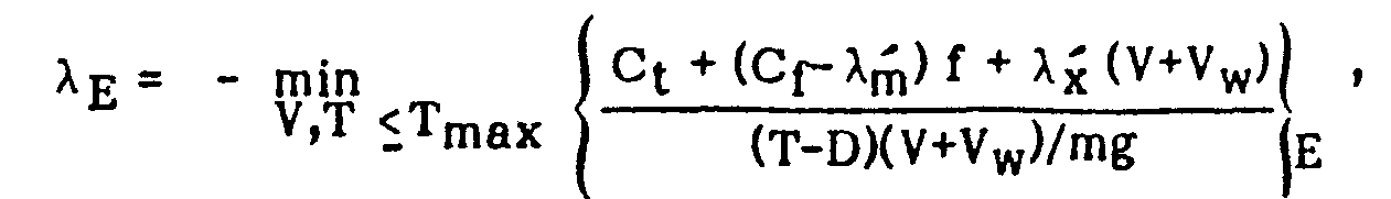
- the processing system includes means for producing optimal aircraft climb target signals and the energy adjoint variable, ⁇ E , in accordance with: wherein T max is a predetermined maximum thrust signal level and the signal processing system thereby produces target airspeed and thrust signals.
- the processing system includes means for producing optimal aircraft descent target signals and the energy adjoint variable, X E , in accordance with: where T m i n is a predetermined minimum thrust signal level, and the signal processing system thereby produces target airspeed and thrust signals.
- FIG. 1 is a detailed block diagram illustrating the various hardware components which comprise the preferred embodiment of the invention.
- aircraft onboard monitoring systems include a data base system 12, a control display unit (CDU) 14, an inertial reference system (IRS) 16, onboard radio systems 18, a digital data computer (DADC) 20, and an engine indication and alerting system (EICAS) 22.
- CDU control display unit
- IRS inertial reference system
- DADC digital data computer
- EICAS engine indication and alerting system
- the data base system 12 is normally included within an onboard flight management computer system. Provided within the data base is information relating to navigation and aircraft performance characteristics. Corresponding navigation and performance data base signals are routed to an onboard computer system 30.
- the control display unit 14 provides two-way communication between the flight crew and the onboard computer 30. This unit allows the flight crew to input parameters such as windspeed, temperature, cost-index, gross weight, and time assignment (i.e. desired time of arrival) to the computer 30 and correspondingly receive computer control information.
- the inertial reference system 16 provides inputs to the computer 30 corresponding to the aircraft's present position and speed.
- the radio systems 18 provide ranging information such as are produced by distance measuring equipment (DME).
- DME distance measuring equipment
- the digital air data computer 20 produces output signals corresponding to aircraft calibrated airspeed; Mach and altitude.
- the engine indication and alerting system 22 produces inputs to the computer 30 corresponding to fuel flow.
- the onboard computer 30 not only receives the inputs from the monitoring systems 10, as well as the input system through the control display unit 14, but also interfaces with associated memory 32.
- memory 32 includes both random access memory (RAM) and read only memory (ROM).
- RAM random access memory
- ROM read only memory
- Stored in the electronic memory 32 are signals corresponding to aircraft characteristics and algorithms to be used by the onboard computer 30 in calculating the target trajectory and thrust level settings.
- the onboard computer receives the monitor signals, memory signals and input signals to produce target range and thrust signals, indicated as outputs labeled "TARGET ENERGY,” “TARGET RANGE,” and “TARGET ALTITUDE.” These signals correspond to the optimum trajectory signals for achieving cost effective flight operation. A particular feature of the present invention is that these signals reflect optimum trajectory and thrust values corresponding to rescheduled time assignment, i.e., time of arrival, inputs.
- the target energy, range and altitude signals are passed to an aircraft steering system 40.
- the aircraft steering system processes the input target values and produces output command thrust and flight path angle command signals. These signals are then routed to the aircraft's engines and control surfaces, respectively, to achieve the desired target values.
- the algorithms used by the onboard computer 30 to achieve optimum cost-effectiveness thrust and trajectory target signals are understood as follows.
- the aircraft model used assumed a point mass approximation, that is, state variables describing the vehicle attitude were either omitted or used as control variables.
- the second term on the right-hand side of equation (3) is normally small and can usually be neglected.
- the value e is a small "singular perturbation" parameter that arises as a consequence of the particular aircraft dynamics and an appropriate choice of scaling the equations of motion.
- the energy height E is related to the altitude and the groundspeed through:
- the airspeed V and the thrust T are the control variables, varying within the limits
- V min and V max are functions of altitude and represent the controllability and structural limitations on the aircraft.
- the airplane model also involves the fuel flow rate f(h,M,T), the drag polar C D (C L ,M) and minimum and maximum thrust T m i n (M,h), T max (M,h), respectively, which are modeled using multiple regression methods.
- M denotes the Mach number
- C D the drag coefficient
- C L the lift coefficient
- h the altitude
- the optimization problem is to steer the system described by equations (1)-(3) from an initial state (x i , mi, E i ) at time ti to a final state (x f , m f , E f ) at a fixed final time t f so that the fuel spent is minimized.
- the goal is to minimize the expression: where J is a cost function and C f is the cost of fuel.
- C t is a cost of time to fly the four-dimensional optimal trajectory.
- the problem reduces, therefore, to a direct operating cost optimization problem with free terminal time and cost parameters C f and C t .
- the balance between fuel and time costs may be expressed by the cost index
- the traditional units used in the cost index are C t in dollars per hour and C f in cents per pound.
- the four-dimensional optimization problem is now reduced to finding the correct Ct or CI for an assigned arrival time t f .
- Cruise is that condition of flight in which thrust equals drag.
- the cruise problem must be solved before climb and descent solutions can be obtained.
- the cruise solution (outer solution according to singular perturbation theory) is reduced to:
- the ratio to be minimized is the cruise cost function.
- equation (10) is transformed into: where ⁇ m and ⁇ X correspond to the values produced during the cruise mode.
- equation (I4) the energy adjoint is taken as: for climb and for descent.
- the minimization is done to get the climb solution, and the maximization to get the descent solution.
- the ratio in equations (15), (16) to be optimized at current energy E is called the climb/descent cost function.
- the assumption here is that energy increases monotonically during time and decreases monotonically during descent.
- the four-dimensional optimization problem is solved from an entry fix (cruise altitude) to an arbitrarily chosen metering fix altitude, such as 10,000 feet.
- the range covered is typically 150 to 200 nautical miles, but it could definitely be greater.
- the same algorithm can be used to generate the entire four-dimensional trajectory (climb/cruise/descent). If the optimal cruise altitude is below the present cruise altitude (e.g., when delay needs to be absorbed), there will be an initial descent segment to the optimal cruise altitude and a final descent segment from the optimal cruise altitude to the metering fix altitude. There will be no climb segment.
- the initial segment will comprise a climb segment to the optimal cruise altitude. Irrespective of whether the initial segment is climb or descent, it is always computed forward (from the initial point to the optimal cruise altitude). In the present methodology, equations (15), (16) are optimized at discrete altitudes from the initial point to the optimal cruise altitude to get the optimal speed and thrust. A check should be made to ensure that energy is decreasing if in the descent mode and increasing if in the climb mode. At optimal cruise altitude, the altitude and speed of the initial segment should be forced to match with the cruise altitude and speed at that point. This requires the use of matched asymtotic expansions from singular perturbation theory.
- the final descent segment is always computed backwards from the metering fix altitude to the optimal cruise altitude.
- equations (15), (16) are optimized at discrete altitudes, ensuring that the total energy is increasing as one moves from the metering fix altitude to the optimal cruise altitude.
- matching is accomplished (of speed and altitude) at the top of the descent point.
- FIG. 2 is a detailed logic flow diagram illustrating the logical steps performed by the onboard computer (30 of Figure 1) during cruise climb-descent modes of operation.
- the computer inputs the present data signal levels. This data corresponds to input system monitor signals corresponding to real time aircraft parameters, stored values corresponding to aircraft characteristics, and flight crew input information, such as a rescheduled time of arrival.
- a redundancy system illustrated at block 54, validates the initial input conditions. Modern commercial aircraft employs multiple redundant sensors and corresponding voting systems to select appropriate sensor signals. These voting systems include fault detection apparatus which indicates the presence of a fault condition. Thus, at block 54 a check is made by the onboard computer to assure that the input initial conditions are valid.
- a further diagnostic is performed at 56 in which all integrated circuits in the onboard computer are checked by internal diagnostics.
- internal diagnostic systems for integrated circuits are well known in the art and, as such, will not be described in detail herein. If, at block 56, either all of the computer's integrated circuits do not test as being valid, or at block 54 invalid initial conditions are present, the system promptly sequences to an end block 58 in which no target values are produced.
- the cruise trajectory is calculated at block 60.
- Figure 3 is a detailed logic flow diagram illustrating the steps performed in the cruise trajectory calculation 60 of Figure 2.
- input altitude and speed windows are defined. These values are generally produced either as direct inputs from the pilot or are memory stored and correspond to the maximum and minimum values of altitude and speed that are acceptable.
- altitude error and speed error tolerances are defined. These values, which may be either memory stored or pilot input, correspond to the maximum acceptable error in altitude and speed tolerances which will be accepted during the following cruise trajectory calculations, i.e., if the calculated trajectory value falls within the error tolerances, the calculated value will be acceptable as a target level.
- the Fibonacci search method is then used to minimize the ratio of: with respect to altitude and speed. In other words, the minimization of equation (13) is performed. All Xm terms are deleted under the assumption that X m is negligible.
- a test is performed. If the calculated altitude and speed values are outside of the windows and error tolerances as defined in blocks 80, 82, respectively, the test at block 86 fails and a recalculation is done in accordance with block 84. Upon the calculated values being within acceptable tolerances, block 88 is entered at which point calculations are made of the time spent, fuel spent and cruise cost and range covered if the suggested trajectory and thrust target values produced from block 84 are accepted. This trajectory information is then stored in block 90, with an update of range being performed in block 92 according to the equation:
- a test is done at block 62.
- the test at block 62 determines whether or not an initial climb is necessary to ascend from the present cruise trajectory to a higher trajectory. If the test at block 62 indicates that climb must be accomplished,-the computer then calculates the climb trajectory as indicated at block 64.
- Figure 4 is a detailed logic flow diagram illustrating the steps performed by the onboard computer to calculate the climb trajectory target values.
- initial trajectory conditions are input at block 100.
- pilot or onboard stored system speed and thrust windows are defined.
- the cruise cost function which is produced at the output of block 84 of Figure 3, is retrieved.
- the speed error and thrust error tolerances are defined, just as the altitude error and airspeed error tolerances were defined in block 82 of Figure 3.
- the Fibonacci search method is used to minimize the expression with respect to thrust and speed. That is, the minimization in accordance with equation (15) is performed. Again, all Xm terms are deleted under the assumption that X m is negligible. This results in target thrust and speed signals which, in block 110, are compared to the thrust and speed error tolerance values. If the target values are not within the error tolerances, a recalculation is done in block 108. This recalculation continues until the error tolerances are met, as determined by block 110, whereby, in block 112 a calculation is made of time spent, fuel spent, climb cost and range covered in accordance with the calculated target values. Then, at block 114, energy height (specific energy) is updated.
- the system determines at block 68 whether an initial descent is necessary. If an initial descent is necessary, block 70 is entered, in which the onboard computer calculates initial descent trajectory target values. The initial descent trajectory values are calculated in accordance with the detailed logic flow diagram of Figure 5, as described below. The calculated initial descent trajectory values are matched at the cruise altitude with cruise in block 72 to assure continuity.
- test at block 68 indicates that an initial descent is not necessary, again the initial conditions are matched with cruise values at block 74. The system then enters the final descent trajectory calculations, indicated by block 76.
- Figure 5 is a detailed logic flow diagram illustrating both the initial and final descent trajectory calculations as indicated by blocks 70 and 76 of Figure 2.
- a test at block 130 determines whether an initial or final descent is being accomplished. If a final descent is being accomplished, block 132 is entered at which point final conditions are input. If an initial descent is being accomplished, a block 134 is entered at which point the initial conditions are entered.
- speed and thrust windows are defined either by the pilot or are stored in the onboard system.
- cruise cost function is retrieved from block 84 of Figure 3.
- Speed error and thrust error tolerances are defined at block 140.
- the Fibonacci search method is used to maximize the expression with respect to thrust and speed, corresponding to equation (16). Again, ⁇ m terms are deleted with the assumption that ⁇ m is negligible.
- time, weight (mg) and range x are updated in block 154 and the Fibonacci search method of block 142 is again entered to calculate new target values. If, however, the energy height value is less than the cruise energy level, descent is indicated as being complete at block 156.
- block 158 is entered at which point energy height is updated for final descent.
- a test is then performed at block 160 to determine whether the energy height is greater than the predefined cruise energy. If energy heignt is less than the cruise energy, time, weight and range are updated, in accordance with block 162. The Fibonacci search method of block 142 is then entered to calculate new target values. If, at block 160, it is determined that energy height is greater than the cruise energy, descent is complete as indicated by block 156, whereby the overall system of Figure 2 is again entered.
- the onboard computer calculates the total time and time error values.
- a calculation is made of total fuel.
- a test is then performed at 84 to determine whether or not the calculated time error is less than a specified value, here indicated as 5 seconds. If the time error is not less than 5 seconds, the time error is used, in block 86, to calculate a new cost index in accordance with the equation indicated in block 86. With this new cost index, the cruise trajectory targets of block 60 are again calculated.
- the system stores the final trajectory values in block 88, both indicating the end of trajectory calculations, in block 58, and outputting the target values to the aircraft's steering system 40 (as also shown in Figure 1).
Landscapes
- Engineering & Computer Science (AREA)
- Aviation & Aerospace Engineering (AREA)
- Radar, Positioning & Navigation (AREA)
- Remote Sensing (AREA)
- Physics & Mathematics (AREA)
- General Physics & Mathematics (AREA)
- Automation & Control Theory (AREA)
- Navigation (AREA)
- Control Of Position, Course, Altitude, Or Attitude Of Moving Bodies (AREA)
Abstract
Description
- The present invention pertains to the aircraft flight management art and, more particularly, to a flight management computer system which responds to an input time of arrival to produce cost effective trajectory target signals.
- While numerous aircraft fight management control systems are known to the prior art, none of these systems is capable of producing optimum trajectory and thrust settings to achieve a desired time of arrival. Presently, a pilot, upon receiving a rescheduled time of arrival, will either alter his thrust but maintain present trajectory or, upon arrival early at a destination, assume a holding position until a landing can be accomplished. Whichever of these options the pilot chooses, it is doubtful that the aircraft trajectory and thrust levels are optimum for the most cost effective aircraft operation.
- Overall flight planning is presently performed by on-ground dispatch computers. During flight, however, as time of arrival is rescheduled, the aircraft's onboard flight management system is incapable of computing the optimum trajectory and thrust levels to achieve the desired time of arrival. As a result, aircraft have been flown in less than optimum cost effective conditions, thereby leading to wasted fuel and increased cost of operation.
- The present invention, therefore, is directed to an improved aircraft airborne flight management computer system, which system is capable of producing optimum trajectory and thrust target values as a function of desired time of arrival.
- Briefly, according to the invention, an aircraft time-responsive trajectory optimization system includes a monitor for producing signals representative of predetermined real time aircraft parameters. Onboard memory stores and produces signals representing predetermined aircraft performance characteristics. A system input is provided for producing signals representing a desired aircraft time and place of arrival. Onboard processing means, preferably in the form of a flight management computer, processes the signals produced by the monitor, memory and system input to produce target aircraft trajectory and speed signals corresponding to an optimum cost effective flight trajectory for arriving at the desired time.
- In one aspect of the invention, the monitor produces signals representative of fuel flow rate, f, airspeed, V, windspeed, Vw, thrust, T, drag, D, and aircraft mass, m. The onboard memory stores and produces signals representative of aircraft cost index, Ct, fuel cost index, Cf, and the acceleration due to gravity, g. The onboard processing means produces aircraft thrust and airspeed values which minimize the expression:

- In a further aspect of the invention, the processing means includes means for producing optimal cruise target signals and the range adjoint variable, λx, in accordance with:

- In yet a further aspect of the invention, the processing system includes means for producing optimal aircraft climb target signals and the energy adjoint variable, λE, in accordance with:
- In still a further aspect of the invention, the processing system includes means for producing optimal aircraft descent target signals and the energy adjoint variable, X E, in accordance with:

-
- Figure 1 is a block diagram illustrating the principal hardware components of the preferred embodiment of the invention;
- Figure 2 is a logic flow diagram illustrating the overall cruise climb-descent modes of operation as performed by the onboard computer;
- Figure 3 is a detailed logic flow diagram illustrating each step performed by the onboard computer in producing target cruise trajectory signals;
- Figure 4 is a detailed logic flow diagram illustrating each step performed by the onboard computer in producing target climb trajectory signals; and
- Figure 5 is a detailed logic flow diagram illustrating each step performed by the onboard computer in producing target descent trajectory signals.
- Figure 1 is a detailed block diagram illustrating the various hardware components which comprise the preferred embodiment of the invention. Here, aircraft onboard monitoring systems, indicated generally at 10, include a
data base system 12, a control display unit (CDU) 14, an inertial reference system (IRS) 16, onboardradio systems 18, a digital data computer (DADC) 20, and an engine indication and alerting system (EICAS) 22. - The
data base system 12 is normally included within an onboard flight management computer system. Provided within the data base is information relating to navigation and aircraft performance characteristics. Corresponding navigation and performance data base signals are routed to anonboard computer system 30. - The
control display unit 14 provides two-way communication between the flight crew and theonboard computer 30. This unit allows the flight crew to input parameters such as windspeed, temperature, cost-index, gross weight, and time assignment (i.e. desired time of arrival) to thecomputer 30 and correspondingly receive computer control information. - The
inertial reference system 16 provides inputs to thecomputer 30 corresponding to the aircraft's present position and speed. - The
radio systems 18 provide ranging information such as are produced by distance measuring equipment (DME). - The digital
air data computer 20 produces output signals corresponding to aircraft calibrated airspeed; Mach and altitude. - Finally, the engine indication and alerting
system 22 produces inputs to thecomputer 30 corresponding to fuel flow. - The
onboard computer 30 not only receives the inputs from themonitoring systems 10, as well as the input system through thecontrol display unit 14, but also interfaces withassociated memory 32. In this, the preferred embodiment of the invention,memory 32 includes both random access memory (RAM) and read only memory (ROM). Stored in theelectronic memory 32 are signals corresponding to aircraft characteristics and algorithms to be used by theonboard computer 30 in calculating the target trajectory and thrust level settings. - In accordance with the logic flow diagrams shown in Figures 2-5, the onboard computer receives the monitor signals, memory signals and input signals to produce target range and thrust signals, indicated as outputs labeled "TARGET ENERGY," "TARGET RANGE," and "TARGET ALTITUDE." These signals correspond to the optimum trajectory signals for achieving cost effective flight operation. A particular feature of the present invention is that these signals reflect optimum trajectory and thrust values corresponding to rescheduled time assignment, i.e., time of arrival, inputs.
- The target energy, range and altitude signals are passed to an
aircraft steering system 40. The aircraft steering system, of conventional design, processes the input target values and produces output command thrust and flight path angle command signals. These signals are then routed to the aircraft's engines and control surfaces, respectively, to achieve the desired target values. - The algorithms used by the
onboard computer 30 to achieve optimum cost-effectiveness thrust and trajectory target signals are understood as follows. The aircraft model used assumed a point mass approximation, that is, state variables describing the vehicle attitude were either omitted or used as control variables. The energy-state approximation of the point-mass longitudinal model of the aircraft, in the presence of wind, was then taken in conventional state variables as follows:


- The airspeed V and the thrust T are the control variables, varying within the limits


- Both Vmin and Vmax are functions of altitude and represent the controllability and structural limitations on the aircraft. The airplane model also involves the fuel flow rate f(h,M,T), the drag polar CD(CL,M) and minimum and maximum thrust Tmin(M,h), Tmax(M,h), respectively, which are modeled using multiple regression methods. M denotes the Mach number, CD the drag coefficient, CL the lift coefficient, and h the altitude.
- The optimization problem is to steer the system described by equations (1)-(3) from an initial state (xi, mi, Ei) at time ti to a final state (xf, mf, Ef) at a fixed final time tf so that the fuel spent is minimized. Equivalently, the goal is to minimize the expression:

- The Hamiltonian for equations 1-3 and 7 is:


- The symbol Ct is a cost of time to fly the four-dimensional optimal trajectory. The problem reduces, therefore, to a direct operating cost optimization problem with free terminal time and cost parameters Cf and Ct. The balance between fuel and time costs may be expressed by the cost index

- The traditional units used in the cost index are Ct in dollars per hour and Cf in cents per pound. The four-dimensional optimization problem is now reduced to finding the correct Ct or CI for an assigned arrival time tf.
- Cruise is that condition of flight in which thrust equals drag. Using the present methodology, the cruise problem must be solved before climb and descent solutions can be obtained. As e approaches zero, the cruise solution (outer solution according to singular perturbation theory) is reduced to:


- During climb/descent, equation (10) is transformed into:


- The minimization is done to get the climb solution, and the maximization to get the descent solution. The ratio in equations (15), (16) to be optimized at current energy E is called the climb/descent cost function. The assumption here is that energy increases monotonically during time and decreases monotonically during descent.
- While the detailed steps performed by the onboard computer to realize the optimization law are given in detail in Figures 2-5, the following brief explanation will aid in a complete understanding. The four-dimensional optimization problem is solved from an entry fix (cruise altitude) to an arbitrarily chosen metering fix altitude, such as 10,000 feet. The range covered is typically 150 to 200 nautical miles, but it could definitely be greater. The same algorithm can be used to generate the entire four-dimensional trajectory (climb/cruise/descent). If the optimal cruise altitude is below the present cruise altitude (e.g., when delay needs to be absorbed), there will be an initial descent segment to the optimal cruise altitude and a final descent segment from the optimal cruise altitude to the metering fix altitude. There will be no climb segment.
- Conversely, if the optimal cruise altitude is above the present altitude, the initial segment will comprise a climb segment to the optimal cruise altitude. Irrespective of whether the initial segment is climb or descent, it is always computed forward (from the initial point to the optimal cruise altitude). In the present methodology, equations (15), (16) are optimized at discrete altitudes from the initial point to the optimal cruise altitude to get the optimal speed and thrust. A check should be made to ensure that energy is decreasing if in the descent mode and increasing if in the climb mode. At optimal cruise altitude, the altitude and speed of the initial segment should be forced to match with the cruise altitude and speed at that point. This requires the use of matched asymtotic expansions from singular perturbation theory.
- The final descent segment is always computed backwards from the metering fix altitude to the optimal cruise altitude. Again, equations (15), (16) are optimized at discrete altitudes, ensuring that the total energy is increasing as one moves from the metering fix altitude to the optimal cruise altitude. As before, matching is accomplished (of speed and altitude) at the top of the descent point.
- Figure 2 is a detailed logic flow diagram illustrating the logical steps performed by the onboard computer (30 of Figure 1) during cruise climb-descent modes of operation. At
block 52, the computer inputs the present data signal levels. This data corresponds to input system monitor signals corresponding to real time aircraft parameters, stored values corresponding to aircraft characteristics, and flight crew input information, such as a rescheduled time of arrival. A redundancy system, illustrated atblock 54, validates the initial input conditions. Modern commercial aircraft employs multiple redundant sensors and corresponding voting systems to select appropriate sensor signals. These voting systems include fault detection apparatus which indicates the presence of a fault condition. Thus, at block 54 a check is made by the onboard computer to assure that the input initial conditions are valid. - A further diagnostic is performed at 56 in which all integrated circuits in the onboard computer are checked by internal diagnostics. Such internal diagnostic systems for integrated circuits are well known in the art and, as such, will not be described in detail herein. If, at block 56, either all of the computer's integrated circuits do not test as being valid, or at
block 54 invalid initial conditions are present, the system promptly sequences to anend block 58 in which no target values are produced. - If, however, both valid conditions and valid IC's are detected at block 56, the cruise trajectory is calculated at
block 60. - Figure 3 is a detailed logic flow diagram illustrating the steps performed in the
cruise trajectory calculation 60 of Figure 2. First, atblock 80, input altitude and speed windows are defined. These values are generally produced either as direct inputs from the pilot or are memory stored and correspond to the maximum and minimum values of altitude and speed that are acceptable. - Then, at
block 82, altitude error and speed error tolerances are defined. These values, which may be either memory stored or pilot input, correspond to the maximum acceptable error in altitude and speed tolerances which will be accepted during the following cruise trajectory calculations, i.e., if the calculated trajectory value falls within the error tolerances, the calculated value will be acceptable as a target level. - At
block 84 the Fibonacci search method is then used to minimize the ratio of:
- At block 86 a test is performed. If the calculated altitude and speed values are outside of the windows and error tolerances as defined in
blocks block 86 fails and a recalculation is done in accordance withblock 84. Upon the calculated values being within acceptable tolerances, block 88 is entered at which point calculations are made of the time spent, fuel spent and cruise cost and range covered if the suggested trajectory and thrust target values produced fromblock 84 are accepted. This trajectory information is then stored inblock 90, with an update of range being performed inblock 92 according to the equation:
- A test is then performed at
block 94. If the present value of range, as determined inblock 92 is less than the given range value, then an update is performed atblock 96 of time and weight (= mg). These values are then reinserted into the Fibonacci search method ofblock 84 and new target values are calculated. If, however, atblock 94 the present value of range as determined byblock 92 is greater than the given range value, then the cruise mode is complete, as indicated byblock 98, and the system returns to block 60 of Figure 2. - Referring again to Figure 2, once the cruise mode is completed at
block 60, a test is done atblock 62. The test atblock 62 determines whether or not an initial climb is necessary to ascend from the present cruise trajectory to a higher trajectory. If the test atblock 62 indicates that climb must be accomplished,-the computer then calculates the climb trajectory as indicated atblock 64. - Figure 4 is a detailed logic flow diagram illustrating the steps performed by the onboard computer to calculate the climb trajectory target values. Here, initial trajectory conditions are input at block 100. Then, at
block 102, either pilot or onboard stored system speed and thrust windows are defined. Atblock 104, the cruise cost function, which is produced at the output ofblock 84 of Figure 3, is retrieved. Then, atblock 106, the speed error and thrust error tolerances are defined, just as the altitude error and airspeed error tolerances were defined inblock 82 of Figure 3. - Now, at
block 108, the Fibonacci search method is used to minimize the expression
block 110, are compared to the thrust and speed error tolerance values. If the target values are not within the error tolerances, a recalculation is done inblock 108. This recalculation continues until the error tolerances are met, as determined byblock 110, whereby, in block 112 a calculation is made of time spent, fuel spent, climb cost and range covered in accordance with the calculated target values. Then, atblock 114, energy height (specific energy) is updated. If the energy height calculated fromblock 114 is not greater than the predefined cruise energy as determined byblock 116, time, weight and range are updated, as indicated byblock 118, and the minimization technique ofblock 108 is again entered to recalculate target values. When block 116 determines that the energy height is greater than the predefined cruise energy, the climb mode is then complete, as indicated byblock 120, and the system reverts to block 66 of Figure 2. Referring again to Figure 2, inblock 66 the final climb value is matched with the cruise value to assure continuity. - If the test at
block 62 indicates that an initial climb is not necessary, the system determines atblock 68 whether an initial descent is necessary. If an initial descent is necessary, block 70 is entered, in which the onboard computer calculates initial descent trajectory target values. The initial descent trajectory values are calculated in accordance with the detailed logic flow diagram of Figure 5, as described below. The calculated initial descent trajectory values are matched at the cruise altitude with cruise inblock 72 to assure continuity. - If the test at
block 68 indicates that an initial descent is not necessary, again the initial conditions are matched with cruise values atblock 74. The system then enters the final descent trajectory calculations, indicated by block 76. - Figure 5 is a detailed logic flow diagram illustrating both the initial and final descent trajectory calculations as indicated by blocks 70 and 76 of Figure 2. Referring to Figure 5, a test at block 130 determines whether an initial or final descent is being accomplished. If a final descent is being accomplished, block 132 is entered at which point final conditions are input. If an initial descent is being accomplished, a
block 134 is entered at which point the initial conditions are entered. - Then, at
block 136, speed and thrust windows are defined either by the pilot or are stored in the onboard system. Atblock 138, the cruise cost function is retrieved fromblock 84 of Figure 3. Speed error and thrust error tolerances are defined at block 140. Now, in block 142, the Fibonacci search method is used to maximize the expression
- A test is then made at
block 144 to determine whether or not the error tolerances are met. If the error tolerances are not met, the search method of block 142 is then reentered to calculate new target values. This process continues until acceptable values are output fromblock 144 to block 146 at which point the onboard computer calculates time spent, fuel spent and descent cost and range covered for the target thrust and speed values. Again, a test is made atblock 148 to determine whether or not the descent is a final descent. If the descent is an initial descent, ablock 150 is entered at which the present energy height value is updated. With this value updated, a test is performed at block 152 to determine whether the present energy height is less than a predetermined cruise energy. If it is not less than the predetermined cruise energy, time, weight (mg) and range x are updated inblock 154 and the Fibonacci search method of block 142 is again entered to calculate new target values. If, however, the energy height value is less than the cruise energy level, descent is indicated as being complete atblock 156. - If the test at
block 148 indicates that descent is final, block 158 is entered at which point energy height is updated for final descent. A test is then performed atblock 160 to determine whether the energy height is greater than the predefined cruise energy. If energy heignt is less than the cruise energy, time, weight and range are updated, in accordance withblock 162. The Fibonacci search method of block 142 is then entered to calculate new target values. If, atblock 160, it is determined that energy height is greater than the cruise energy, descent is complete as indicated byblock 156, whereby the overall system of Figure 2 is again entered. - Referring again to Figure 2, once the final descent trajectory out of block 76 is achieved, the end of trajectory values are matched with the final constraints in accordance with block 78. Then, in
block 80, the onboard computer calculates the total time and time error values. Atblock 82, a calculation is made of total fuel. A test is then performed at 84 to determine whether or not the calculated time error is less than a specified value, here indicated as 5 seconds. If the time error is not less than 5 seconds, the time error is used, inblock 86, to calculate a new cost index in accordance with the equation indicated inblock 86. With this new cost index, the cruise trajectory targets ofblock 60 are again calculated. - If time error is determined to be less than the predetermined limit at
block 84, the system stores the final trajectory values inblock 88, both indicating the end of trajectory calculations, inblock 58, and outputting the target values to the aircraft's steering system 40 (as also shown in Figure 1). - In summary, an onboard, time responsive flight optimization system, capable of producing target trajectory and thrust levels for producing optimal cost effectiveness has been described in detail. The features of this invention include the capability to:
- a) Iterate on the cost index and arrive at the assigned time in optimal fashion;
- b) Realize considerable savings potential over the conventional "hold" strategy;
- c) Use multiple regression drag and fuel flow models which are sufficiently smooth to avoid arrival time discontinuities;
- d) Use singular perturbation theory to reduce the order of system dynamics; and
- e) Generate optimal commands using the Fibonacci search technique, therefore avoiding the computation time associated with the calculation of a derivative.
- While a preferred embodiment of the invention has been described in detail, it should be apparent that many modifications and variations thereto are possible, all of which fall within the true spirit and scope of the invention.
Claims (9)
- I. An aircraft time-responsive trajectory optimization system comprising:monitor means for producing signals representative of predetermined real time aircraft parameters;memory means for producing signals representative of predetermined aircraft performance characteristics;input means for producing signals representative of a desired aircraft time and place of arrival; andprocessing means for processing the signals produced by said monitor means, memory means and input means and producing target aircraft trajectory and speed signals corresponding to an optimum cost effectiveness flight trajectory for arriving at said time.
- 2. The trajectory optimization system of claim I wherein:said monitor means produces signals representative of fuel flow rate, f, airspeed, V, windspeed, Vw, thrust, T, drag, D, and aircraft mass, m;said memory means produces signals representative of aircraft time cost, Ct, fuel cost, Cf, and the acceleration due to gravity, g; andsaid processing means produces aircraft thrust and airspeed target values which minimize the expression:

- 3. The trajectory optimization system of claim 2 wherein said processing means includes means for producing optimal cruise target signals and said range adjoint variable, λX, in accordance with:

said processing means thereby producing target altitude and airspeed signals. - 4. The trajectory optimization system of claim 3 wherein said processing means includes means for producing optimal aircraft climb target signals and said energy adjoint variable, λE, in accordance with:

said signal processing means thereby producing target airspeed and thrust signals. - 5. The trajectory optimization system of either claim 3 or claim 4 wherein said processing means includes means for producing optimal aircraft descent targets and said energy adjoint variable, λE, in accordance with:
 wherein Tmin is a predetermined minimum thrust signal level produced by said memory means,said signal processing means thereby producing target airspeed and thrust signals.
 - 6. The trajectory optimization system of any one of claims 2 through 4 wherein said processing means includes means for treating said λm signal as having negligible value.
- 7. The trajectory optimization system of claim 5 wherein said processing means includes means for treating said λm signal as having negligible value.
- 8. The trajectory optimization system of any one of claims 1 to 4 further comprising:aircraft steering system means responsive to said aircraft target signals to produce said optimum trajectory.
- 9. The trajectory optimization system of claim 5 further comprising:aircraft steering system means responsive to said aircraft target signals to produce said optimum trajectory.
Applications Claiming Priority (2)
| Application Number | Priority Date | Filing Date | Title |
|---|---|---|---|
| US82652586A | 1986-02-06 | 1986-02-06 | |
| US826525 | 1986-02-06 |
Publications (2)
| Publication Number | Publication Date |
|---|---|
| EP0236587A2 true EP0236587A2 (en) | 1987-09-16 |
| EP0236587A3 EP0236587A3 (en) | 1989-03-22 |
Family
ID=25246777
Family Applications (1)
| Application Number | Title | Priority Date | Filing Date |
|---|---|---|---|
| EP86201678A Withdrawn EP0236587A3 (en) | 1986-02-06 | 1986-09-29 | Time-responsive flight optimization system |
Country Status (2)
| Country | Link |
|---|---|
| US (1) | US5457634A (en) |
| EP (1) | EP0236587A3 (en) |
Cited By (11)
| Publication number | Priority date | Publication date | Assignee | Title |
|---|---|---|---|---|
| US5486995A (en) * | 1994-03-17 | 1996-01-23 | Dow Benelux N.V. | System for real time optimization |
| WO1997048028A1 (en) * | 1996-06-14 | 1997-12-18 | Sextant Avionique | Aircraft flight management system |
| US6038540A (en) * | 1994-03-17 | 2000-03-14 | The Dow Chemical Company | System for real-time economic optimizing of manufacturing process control |
| FR2916842A1 (en) * | 2007-06-01 | 2008-12-05 | Thales Sa | METHOD OF OPTIMIZING A FLIGHT PLAN |
| US7765062B2 (en) | 2006-04-25 | 2010-07-27 | Honeywell International Inc. | Method and system for autonomous tracking of a mobile target by an unmanned aerial vehicle |
| US7970722B1 (en) | 1999-11-08 | 2011-06-28 | Aloft Media, Llc | System, method and computer program product for a collaborative decision platform |
| EP2685292A3 (en) * | 2012-07-12 | 2014-06-18 | General Electric Company | Systems and methods for flight management |
| US9483058B2 (en) | 2014-07-04 | 2016-11-01 | Rolls-Royce Plc | Aircraft control method |
| EP3193268A1 (en) * | 2016-01-13 | 2017-07-19 | The Boeing Company | Systems and methods for providing airplane performance calculations |
| EP3211621A1 (en) * | 2016-02-29 | 2017-08-30 | The Boeing Company | Method and electronic device for optimizing a flight trajectory of an aircraft subject to time of arrival control constraints |
| EP3598261A1 (en) * | 2018-07-17 | 2020-01-22 | Ge Aviation Systems Llc, Inc. | Method and system for determining a descent profile |
Families Citing this family (44)
| Publication number | Priority date | Publication date | Assignee | Title |
|---|---|---|---|---|
| US6002972A (en) * | 1992-11-18 | 1999-12-14 | Aers/Midwest, Inc. | Method and apparatus for measuring forces based upon differential pressure between surfaces of an aircraft |
| US5796612A (en) | 1992-11-18 | 1998-08-18 | Aers/Midwest, Inc. | Method for flight parameter monitoring and control |
| US5842142A (en) * | 1995-05-15 | 1998-11-24 | The Boeing Company | Least time alternate destination planner |
| FR2734359B1 (en) * | 1995-05-17 | 1997-07-18 | Eurocopter France | METHOD AND DEVICE FOR DETERMINING THE FLIGHT CONFIGURATIONS OF AN AIRCRAFT |
| US5761625A (en) * | 1995-06-07 | 1998-06-02 | Alliedsignal Inc. | Reconfigurable algorithmic networks for aircraft data management |
| US5878356A (en) * | 1995-06-14 | 1999-03-02 | Agrometrics, Inc. | Aircraft based infrared mapping system for earth based resources |
| US5742922A (en) * | 1996-02-12 | 1998-04-21 | Hyundai Motor Company | Vehicle navigation system and method for selecting a route according to fuel consumption |
| US6112140A (en) * | 1996-05-14 | 2000-08-29 | The Boeing Company | Flight management system providing for automatic control display unit backup utilizing structured data routing |
| US5751609A (en) * | 1996-10-24 | 1998-05-12 | The United States Of America As Represented By The Secretary Of The Navy | Neural network based method for estimating helicopter low airspeed |
| US5908176A (en) * | 1997-01-14 | 1999-06-01 | The United States Of America As Represented By The Administrator Of The National Aeronautics And Space Administration | In-flight adaptive performance optimization (APO) control using redundant control effectors of an aircraft |
| FR2774359B1 (en) * | 1998-01-30 | 2000-04-07 | Aerospatiale | ENGINE CONTROL SYSTEM FOR AIRCRAFT |
| US5987397A (en) * | 1998-03-13 | 1999-11-16 | The United States Of America As Represented By The Secretary Of The Navy | Neural network system for estimation of helicopter gross weight and center of gravity location |
| US6188937B1 (en) * | 1998-09-30 | 2001-02-13 | Honeywell International Inc. | Methods and apparatus for annunciation of vehicle operational modes |
| US6266610B1 (en) * | 1998-12-31 | 2001-07-24 | Honeywell International Inc. | Multi-dimensional route optimizer |
| US6450112B1 (en) * | 1999-04-02 | 2002-09-17 | Nautronix, Inc. | Vessel control force allocation optimization |
| US6259976B1 (en) | 1999-09-25 | 2001-07-10 | Jerome H. Lemelson | Fuzzy logic based emergency flight control with thrust vectoring |
| US6696930B1 (en) | 2000-04-10 | 2004-02-24 | Teledyne Technologies Incorporated | System and method for specification of trigger logic conditions |
| DE10030036B4 (en) * | 2000-06-17 | 2014-07-17 | Eads Deutschland Gmbh | Vehicle control system for path control taking into account a flow influencing the vehicle and a method for generating a trajectory |
| US6571155B2 (en) | 2001-07-02 | 2003-05-27 | The Boeing Company | Assembly, computer program product and method for displaying navigation performance based flight path deviation information |
| US6747577B2 (en) * | 2001-11-26 | 2004-06-08 | The Boeing Company | Methods and systems for air vehicle telemetry |
| AUPS241102A0 (en) * | 2002-05-20 | 2002-06-13 | Tmg International Holdings Pty Limited | System for improving timekeeping and saving energy on long-haul trains |
| JP4301861B2 (en) * | 2002-05-20 | 2009-07-22 | 川崎重工業株式会社 | Method and apparatus for maneuvering moving body |
| US6915189B2 (en) * | 2002-10-17 | 2005-07-05 | Teledyne Technologies Incorporated | Aircraft avionics maintenance diagnostics data download transmission system |
| FR2854128B1 (en) * | 2003-04-22 | 2006-04-07 | Airbus France | STEERING INDICATOR FOR AN AIRCRAFT, IN PARTICULAR A TRANSPORT PLANE, FOR PROVIDING THE THRUST GENERATED BY AT LEAST ONE ENGINE OF THE AIRCRAFT |
| EP1625670B1 (en) * | 2003-04-28 | 2008-09-10 | BVR Systems (1998) Limited | Global positioning system receiver |
| US7177785B2 (en) * | 2003-08-22 | 2007-02-13 | Honeywell International, Inc. | Systems and methods for improved aircraft performance predictions |
| FR2872327B1 (en) * | 2004-06-28 | 2006-10-06 | Avions De Transp Regional Grou | METHOD AND DEVICE FOR DETECTING PERFORMANCE DEGRADATION OF AN AIRCRAFT |
| US7702427B1 (en) * | 2004-07-30 | 2010-04-20 | The United States Of America As Represented By The National Aeronautics And Space Administration (Nasa) | Air traffic management evaluation tool |
| US7248949B2 (en) * | 2004-10-22 | 2007-07-24 | The Mitre Corporation | System and method for stochastic aircraft flight-path modeling |
| EP1770365B1 (en) * | 2005-09-30 | 2011-11-16 | Saab Ab | Method for planning the velocity of a craft along a route |
| US7984146B2 (en) * | 2006-05-04 | 2011-07-19 | Sikorsky Aircraft Corporation | Aircraft health and usage monitoring system with comparative fleet statistics |
| US7606658B2 (en) * | 2007-09-12 | 2009-10-20 | Honeywell International Inc. | Financial decision aid for 4-D navigation |
| US20090083050A1 (en) * | 2007-09-25 | 2009-03-26 | Eltman Joseph T | Compilation and distribution of data for aircraft fleet management |
| US7983809B2 (en) * | 2007-12-21 | 2011-07-19 | Sikorsky Aircraft Corporation | Aircraft integrated support system (ISS) |
| US20090265049A1 (en) * | 2008-04-22 | 2009-10-22 | Honeywell International, Inc. | Aircraft system emissions and noise estimation mechanism |
| FR2944634A1 (en) * | 2009-04-21 | 2010-10-22 | Thales Sa | METHOD FOR DETERMINING THE FUEL QUANTITY ENTERED IN AN AIRCRAFT FOR CONTAINING RTA TYPE TIME CONSTRAINTS |
| US20120232723A1 (en) * | 2009-05-21 | 2012-09-13 | Nance C Kirk | Method to Increase Aircraft Maximum Landing Weight Limitation |
| US8406939B2 (en) * | 2010-09-03 | 2013-03-26 | Honeywell International Inc. | Systems and methods for RTA control of multi-segment flight plans with smooth transitions |
| US10013236B2 (en) * | 2013-03-06 | 2018-07-03 | The Boeing Company | Real-time adaptive speed scheduler |
| US10062291B1 (en) * | 2014-10-21 | 2018-08-28 | The Boeing Company | Systems and methods for providing improved flight guidance |
| US9745052B2 (en) | 2015-10-30 | 2017-08-29 | Ge Aviation Systems Llc | Determining enhanced operating state for aircraft |
| US9911339B2 (en) | 2015-11-05 | 2018-03-06 | Ge Aviation Systems Llc | Experimental real-time performance enhancement for aircraft |
| US10671092B2 (en) | 2017-10-20 | 2020-06-02 | The Boeing Company | Airplane climb thrust optimization |
| US10850868B1 (en) * | 2018-05-29 | 2020-12-01 | Rockwell Collins, Inc. | Operational scenario specific adaptive sensor voter |
Citations (1)
| Publication number | Priority date | Publication date | Assignee | Title |
|---|---|---|---|---|
| GB2027227A (en) * | 1978-07-28 | 1980-02-13 | Boeing Co | Economy performance data avionic system |
Family Cites Families (7)
| Publication number | Priority date | Publication date | Assignee | Title |
|---|---|---|---|---|
| US2766953A (en) * | 1951-07-16 | 1956-10-16 | Honeywell Regulator Co | Flight scheduling apparatus |
| CA851576A (en) * | 1963-10-18 | 1970-09-15 | Guetta Arnold | Automatic engine control system |
| US3612837A (en) * | 1969-04-30 | 1971-10-12 | Bendix Corp | Aircraft strike assurance system |
| US4312041A (en) * | 1978-02-22 | 1982-01-19 | Lear Siegler, Inc. | Flight performance data computer system |
| US4220994A (en) * | 1978-07-27 | 1980-09-02 | Eldon W. Planalp | General purpose navigation aid device |
| US4371934A (en) * | 1979-05-04 | 1983-02-01 | Robert Bosch Gmbh | Vehicle trip computer |
| US4642775A (en) * | 1984-05-25 | 1987-02-10 | Sundstrand Data Control, Inc. | Airborne flight planning and information system |
-
1986
- 1986-09-29 EP EP86201678A patent/EP0236587A3/en not_active Withdrawn
-
1990
- 1990-04-11 US US07/512,618 patent/US5457634A/en not_active Expired - Fee Related
Patent Citations (1)
| Publication number | Priority date | Publication date | Assignee | Title |
|---|---|---|---|---|
| GB2027227A (en) * | 1978-07-28 | 1980-02-13 | Boeing Co | Economy performance data avionic system |
Non-Patent Citations (2)
| Title |
|---|
| JOURNAL OF GUIDANCE, CONTROL AND DYNAMICS, vol. 6, no. 1, January/February 1983, pages 14-19, American Institute of Aeronautics and Astronautics, Inc., New York, US; J.W. BURROWS: "Fuel-optimal aircraft trajectories with fixed arrival times" * |
| JOURNAL OF GUIDANCE, CONTROL AND DYNAMICS, vol. 8, no. 1, January/February 1985, pages 16-22, American Institute of Aeronautics and Astronautics, Inc., New York, US; J. GUIDANCE: "Four-dimensional fuel-optimal guidance in the presence of winds" * |
Cited By (20)
| Publication number | Priority date | Publication date | Assignee | Title |
|---|---|---|---|---|
| US5486995A (en) * | 1994-03-17 | 1996-01-23 | Dow Benelux N.V. | System for real time optimization |
| US6038540A (en) * | 1994-03-17 | 2000-03-14 | The Dow Chemical Company | System for real-time economic optimizing of manufacturing process control |
| WO1997048028A1 (en) * | 1996-06-14 | 1997-12-18 | Sextant Avionique | Aircraft flight management system |
| FR2749933A1 (en) * | 1996-06-14 | 1997-12-19 | Sextant Avionique | PROCESS FOR THE MANAGEMENT OF AIR SPEED WITH A VIEW TO COMPLIANCE WITH THE TIME CONSTRAINTS OF AN AERODYNE IN A CHANGING WEATHER ENVIRONMENT |
| US7970722B1 (en) | 1999-11-08 | 2011-06-28 | Aloft Media, Llc | System, method and computer program product for a collaborative decision platform |
| US8005777B1 (en) | 1999-11-08 | 2011-08-23 | Aloft Media, Llc | System, method and computer program product for a collaborative decision platform |
| US8160988B1 (en) | 1999-11-08 | 2012-04-17 | Aloft Media, Llc | System, method and computer program product for a collaborative decision platform |
| US7765062B2 (en) | 2006-04-25 | 2010-07-27 | Honeywell International Inc. | Method and system for autonomous tracking of a mobile target by an unmanned aerial vehicle |
| FR2916842A1 (en) * | 2007-06-01 | 2008-12-05 | Thales Sa | METHOD OF OPTIMIZING A FLIGHT PLAN |
| US8565938B2 (en) | 2007-06-01 | 2013-10-22 | Thales | Method of optimizing a flight plan |
| EP2685292A3 (en) * | 2012-07-12 | 2014-06-18 | General Electric Company | Systems and methods for flight management |
| US9483058B2 (en) | 2014-07-04 | 2016-11-01 | Rolls-Royce Plc | Aircraft control method |
| EP3193268A1 (en) * | 2016-01-13 | 2017-07-19 | The Boeing Company | Systems and methods for providing airplane performance calculations |
| JP2017124813A (en) * | 2016-01-13 | 2017-07-20 | ザ・ボーイング・カンパニーThe Boeing Company | Systems and methods for providing airplane performance calculations |
| CN106971234A (en) * | 2016-01-13 | 2017-07-21 | 波音公司 | System and method for providing aeroplane performance calculating |
| US10071818B2 (en) | 2016-01-13 | 2018-09-11 | The Boeing Company | Systems and methods for providing airplane performance calculations |
| CN106971234B (en) * | 2016-01-13 | 2020-03-13 | 波音公司 | System and method for displaying predicted values of flight path parameters |
| EP3211621A1 (en) * | 2016-02-29 | 2017-08-30 | The Boeing Company | Method and electronic device for optimizing a flight trajectory of an aircraft subject to time of arrival control constraints |
| EP3598261A1 (en) * | 2018-07-17 | 2020-01-22 | Ge Aviation Systems Llc, Inc. | Method and system for determining a descent profile |
| US11142337B2 (en) | 2018-07-17 | 2021-10-12 | Ge Aviation Systems Llc | Method and system for determining a descent profile |
Also Published As
| Publication number | Publication date |
|---|---|
| EP0236587A3 (en) | 1989-03-22 |
| US5457634A (en) | 1995-10-10 |
Similar Documents
| Publication | Publication Date | Title |
|---|---|---|
| US5457634A (en) | Time-responsive flight optimization system | |
| EP0637787B1 (en) | Apparatus and method for controlling an optimizing aircraft performance calculator to achieve timeconstrained navigation | |
| US5710559A (en) | Flight safety monitoring device for aircraft with alarm | |
| CN111240193B (en) | System and method for optimizing cruise vertical profile subject to time of arrival constraints | |
| US5051910A (en) | Wind forecast error compensation for 4-D guidance in a aircraft flight management system | |
| US8744738B2 (en) | Aircraft traffic separation system | |
| US10345824B2 (en) | Optimum cruise climb tracking for reduced fuel consumption using vertical and lateral navigation | |
| EP0750238A1 (en) | Integrated ground collision avoidance system | |
| US20100198433A1 (en) | Flight Management System with Optimization of the Lateral Flight Plan | |
| EP0719429B1 (en) | Method of airplane performance estimation and prediction | |
| US5113346A (en) | Aircraft automatic landing system with engine out provisions | |
| EP2555179A2 (en) | Aircraft traffic separation system | |
| US20170227377A1 (en) | Aircraft intent processor | |
| EP0999485A2 (en) | Method of automated thrust-based roll guidance limiting | |
| US20200118448A1 (en) | Electronic Device and Method for Optimizing Vertical Profile for Cruise Phase of Flight | |
| CA2782105A1 (en) | Heuristic method for computing performance of an aircraft | |
| US20100274418A1 (en) | Method for Determining the Quantity of Fuel Taken On Board an Aircraft Making it Possible to Maintain a Time Requirement of the RTA Type | |
| US5987397A (en) | Neural network system for estimation of helicopter gross weight and center of gravity location | |
| US11360476B1 (en) | Systems and methods for monitoring aircraft control systems using artificial intelligence | |
| Erzberger et al. | A time-based concept for terminal-area traffic management | |
| US20230359225A1 (en) | System for assisting tracking of a wake vortex for aircrafts | |
| Soppa et al. | GNC concept for automated landing of a large parafoil | |
| US6292720B1 (en) | Trimming process for adapting a simulation system to an automatically controlled reference system | |
| Soloway et al. | Aircraft reconfiguration using neural generalized predictive control | |
| CN115071985A (en) | Artificial intelligence driven emergency pilot assistance system and method |
Legal Events
| Date | Code | Title | Description |
|---|---|---|---|
| PUAI | Public reference made under article 153(3) epc to a published international application that has entered the european phase |
Free format text: ORIGINAL CODE: 0009012 |
|
| AK | Designated contracting states |
Kind code of ref document: A2 Designated state(s): DE FR GB IT NL |
|
| PUAL | Search report despatched |
Free format text: ORIGINAL CODE: 0009013 |
|
| AK | Designated contracting states |
Kind code of ref document: A3 Designated state(s): DE FR GB IT NL |
|
| 17P | Request for examination filed |
Effective date: 19890822 |
|
| 17Q | First examination report despatched |
Effective date: 19910205 |
|
| STAA | Information on the status of an ep patent application or granted ep patent |
Free format text: STATUS: THE APPLICATION IS DEEMED TO BE WITHDRAWN |
|
| 18D | Application deemed to be withdrawn |
Effective date: 19910817 |
|
| RIN1 | Information on inventor provided before grant (corrected) |
Inventor name: CHAKRAVARTY, ABHIJIT J.M. |