EP0235028B1 - Allumeur fixable dans la tuyère d'un propulseur - Google Patents
Allumeur fixable dans la tuyère d'un propulseur Download PDFInfo
- Publication number
- EP0235028B1 EP0235028B1 EP87400337A EP87400337A EP0235028B1 EP 0235028 B1 EP0235028 B1 EP 0235028B1 EP 87400337 A EP87400337 A EP 87400337A EP 87400337 A EP87400337 A EP 87400337A EP 0235028 B1 EP0235028 B1 EP 0235028B1
- Authority
- EP
- European Patent Office
- Prior art keywords
- igniter
- nozzle
- disc
- central body
- shear
- Prior art date
- Legal status (The legal status is an assumption and is not a legal conclusion. Google has not performed a legal analysis and makes no representation as to the accuracy of the status listed.)
- Expired - Lifetime
Links
- 230000002093 peripheral effect Effects 0.000 claims description 22
- 239000003380 propellant Substances 0.000 claims description 17
- 239000007789 gas Substances 0.000 claims description 4
- 239000007787 solid Substances 0.000 claims 2
- 230000000717 retained effect Effects 0.000 claims 1
- 238000005452 bending Methods 0.000 description 9
- 238000000465 moulding Methods 0.000 description 5
- 238000002485 combustion reaction Methods 0.000 description 4
- 238000010304 firing Methods 0.000 description 3
- 238000009434 installation Methods 0.000 description 2
- 239000000463 material Substances 0.000 description 2
- 239000004033 plastic Substances 0.000 description 2
- 238000010008 shearing Methods 0.000 description 2
- 239000004449 solid propellant Substances 0.000 description 2
- 239000004831 Hot glue Substances 0.000 description 1
- XAGFODPZIPBFFR-UHFFFAOYSA-N aluminium Chemical compound [Al] XAGFODPZIPBFFR-UHFFFAOYSA-N 0.000 description 1
- 229910052782 aluminium Inorganic materials 0.000 description 1
- 239000000567 combustion gas Substances 0.000 description 1
- 239000004020 conductor Substances 0.000 description 1
- 238000003754 machining Methods 0.000 description 1
- 238000012423 maintenance Methods 0.000 description 1
- 238000000034 method Methods 0.000 description 1
- 239000008188 pellet Substances 0.000 description 1
- 239000004417 polycarbonate Substances 0.000 description 1
- 229920000515 polycarbonate Polymers 0.000 description 1
- 239000000843 powder Substances 0.000 description 1
- 230000000284 resting effect Effects 0.000 description 1
- 238000007789 sealing Methods 0.000 description 1
- 238000000926 separation method Methods 0.000 description 1
- 230000007704 transition Effects 0.000 description 1
Images
Classifications
-
- F—MECHANICAL ENGINEERING; LIGHTING; HEATING; WEAPONS; BLASTING
- F42—AMMUNITION; BLASTING
- F42B—EXPLOSIVE CHARGES, e.g. FOR BLASTING, FIREWORKS, AMMUNITION
- F42B3/00—Blasting cartridges, i.e. case and explosive
- F42B3/26—Arrangements for mounting initiators; Accessories therefor, e.g. tools
-
- F—MECHANICAL ENGINEERING; LIGHTING; HEATING; WEAPONS; BLASTING
- F02—COMBUSTION ENGINES; HOT-GAS OR COMBUSTION-PRODUCT ENGINE PLANTS
- F02K—JET-PROPULSION PLANTS
- F02K9/00—Rocket-engine plants, i.e. plants carrying both fuel and oxidant therefor; Control thereof
- F02K9/95—Rocket-engine plants, i.e. plants carrying both fuel and oxidant therefor; Control thereof characterised by starting or ignition means or arrangements
-
- F—MECHANICAL ENGINEERING; LIGHTING; HEATING; WEAPONS; BLASTING
- F02—COMBUSTION ENGINES; HOT-GAS OR COMBUSTION-PRODUCT ENGINE PLANTS
- F02K—JET-PROPULSION PLANTS
- F02K9/00—Rocket-engine plants, i.e. plants carrying both fuel and oxidant therefor; Control thereof
- F02K9/97—Rocket nozzles
- F02K9/978—Closures for nozzles; Nozzles comprising ejectable or discardable elements
Definitions
- the invention relates to a pyrotechnic igniter which can be fitted and which can be removed from the neck of the nozzle of a propellant, this propellant containing in particular a charge of solid propellant.
- the fixing of this igniter is effected by means of a part which is in abutment on the nozzle convergent and another part which is in abutment on the diverging point of the nozzle.
- igniters which can be fixed in the nozzles of the propellants have been known for many years, and for example around 1950 the patents US 2,720,749 and US 2,776,623 mentioned such igniters.
- the igniter was screwed into the diverging portion of the nozzle by means of a threaded ring initially connected to this diverging portion by destructible fingers. If such an igniter can be installed and can be removed from the nozzle neck at any time, it should however be noted that excessive screwing of the igniter on the ring may damage the fingers by shearing, which would lead to too early ejection of the igniter when the propellant charge is ignited. In addition, in all cases, this ejection of the igniter at the time of ignition only takes place after the positioning fingers have been torn off, such tearing not allowing the igniter to be ejected in determined and reproducible pressure conditions. This tearing which is due to the taper of the divergent also causes a disturbance of the gas jet since after tearing the rest of each finger forms a projection in the diverging.
- US Patent 2,776,623 relates to a completely different type of igniter whose body is made of plastic and which has a diameter much greater than the diameter of the throat of the nozzle. Such an igniter body must be destroyed and expelled by the nozzle after the ignition of the propellant, which qi randomly disrupts the start of propulsion and, to remedy this drawback, improvements have been proposed in particular in patents FR 2 392 240 and EP 0 118 595.
- the expulsion of the igniter is carried out under less variable and more reproducible pressure conditions than the conditions obtained by the implementation of prior techniques, from the fact of the cutting of fins resting on the convergent of the nozzle, but such igniters can no longer be put in place and removed from the neck of the nozzle at any time, in particular for security and interchangeability conditions.
- igniter which is mountable and dismountable at any time and which, at the time of ignition, can be expelled in a reproducible manner.
- an igniter is for example described in US Pat. No. 3,304,865.
- the igniter described in this patent comprises a ferrule engaged in the convergent - divergent from the nozzle, a central body carrying the ignition device proper and a flexible diaphragm intended to ensure positioning by wedging the ferrule in the nozzle converging.
- Such an igniter responds well to the objectives set out above but has the drawback of requiring, for assembly and disassembly, the separation of the nozzle from the propellant unit, the shell of the igniter which is the subject of US Pat. No. 3,304,865 being unable to be inserted or removed only from the front of the nozzle.
- the present invention aims to allow the installation and removal of an igniter in the nozzle of a propellant, while allowing the expulsion of this igniter after firing of the propellant charge under pressure conditions well determined and reproducible, and without disturbing the flow of combustion gases.
- a comprising of parts, which after fitting of the igniter in said nozzle, are supported on the convergent and on the diverging part of the nozzle, the parts which are supported on the convergent of the nozzle are radially expandable external fixing means, held in the radially deployed position by holding means comprising a disc, characterized in that the parts bearing on the divergent are such that they cannot be introduced from the convergent to the divergent by the neck of the nozzle and in that the external fixing means are such that before the installation of the holding means, they can be introduced into the nozzle by its divergent side and in that this disc is a shear disc .
- the external means of fixing the igniter are provided in a peripheral shell which is independent of the central body of the igniter, which makes it possible to deploy the external fixing means radially by the introduction of the central body of the igniter. in this peripheral shell, and which thus avoids the use of control rods or any other intermediate device between the external fixing means and the internal rupture element.
- the peripheral ferrule comprises external fixing means which are constituted by at least two lateral bending tabs bearing on the central body of the igniter, these bending tabs can be replaced by independent lateral tabs which are articulated on an axis. or which are wedge-shaped and slide radially. These lateral tabs have an effective thickness towards their free ends greater than the half-difference between the diameter of the nozzle neck and the diameter of the central body of the igniter.
- the internal rupture element is a shear disc which forms a cover, this disc being able to be perforated so as to provide only radial shear tabs.
- This shear disc is initially secured to the central body of the igniter and to the peripheral shell and preferably this disc and the central body are formed in the same part by machining or by molding.
- the central body of the igniter is constituted by a case which contains the ignition charge, and by a central support in connection with the internal rupture element, this support possibly comprising a peripheral edge which constitutes the shear disc. secured to the peripheral shell only by means of a threaded ring.
- this threaded ring has at the end opposite the shear disc at least one internal stop whose internal diameter is less than the shear diameter of the disc.
- the advantages obtained thanks to this invention consist essentially in that the conditions for igniting the propellant charge are improved by the fact that the expulsion of the igniter occurs under determined and reproducible pressure conditions, which in particular makes it possible to limit, or even eliminate, the overpressures of the combustion chamber when the propellant charge ignites.
- the pressure rise gradient of a solid propellant combustion chamber is of the order of 3 to 10 bars per millisecond, and under these conditions any random delay in opening the nozzle. may cause an initial overpressure which must be taken into account when calculating the resistance of the thruster body.
- an internal rupture element integrated in the igniter in particular a shear disc which forms a cover, makes it possible to determine with great precision the internal pressure causing the rupture of this element, while the tearing fingers or paws can only be done with much greater margins of error.
- the expandable external means which ensure the fixing of the igniter on the nozzle convergent are released under perfectly reproducible conditions whose initial instant of this release corresponds to the instant when the rupture means breaks, which is integrated in the igniter, and which according to the invention initially maintains in the deployed position the external fixing means.
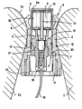
- the figure shows in axial longitudinal section the central part of the nozzle of a propellant which is equipped with an igniter according to the invention.
- the igniter which initially seals the nozzle (1) for ejecting the propellant gases is in abutment on the convergent (1a) and on the divergent (1b) of this nozzle.
- the peripheral shell (4) of this igniter has a conical part, which has the same conicity as the divergent part of the nozzle, which is in contact with this diverging part, and which is extended by a cylindrical part which has a diameter slightly smaller than the diameter of the nozzle neck and is engaged in this neck.
- the transition between these conical and cylindrical parts of the peripheral shell forms a support base for an O-ring seal (12) and, opposite the conical part, this shell is extended by four lateral bending tabs (6) which constitute the external fixing means (3) radially expandable bearing on the convergent (1a) of the nozzle.
- the assembly of the peripheral shell (4) is made of a material allowing the bending of the lateral tabs (6), in particular a plastic material such as polycarbonate, and these tabs are molded in the middle position which is shown in dotted lines in half. right of the figure, the maximum external diameter of these lugs in the molding position being greater than the diameter of the nozzle neck, and the minimum internal diameter of these lugs in the molding position being less than the internal diameter of the peripheral shell (4) .
- the peripheral shell (4) When mounting the igniter in the nozzle (1) - for throwing the propellant gases, the peripheral shell (4) is first introduced alone into the neck of the nozzle by a simple push from the divergent, this push determining the internal bending of the four lateral tabs (6) which resume by elasticity their molding position and ensure the provisional maintenance of this ferrule until the central body (5) of the igniter is slid into this ferrule.
- This central body is constituted by the cylindrical case (8) which contains the ignition charge (9) and by the central support (10) of the igniter on which this case is crimped.
- the establishment of the central body (5) in the peripheral shell (4) determines the external bending of the four lateral legs (6) which are pushed into contact with the convergent (1 a) of the nozzle and ensure the fixing of the igniter in this nozzle after deformation of the O-ring seal (12).
- the central support (10) contains the igniter (13) which is reinforced by an ignition powder and which maintains a flame tube (14) around which the aluminum thermo pellets (15) are stored. ignition contained in the housing (16). This igniter is secured to the igniter holder (17) by means of a hot-melt adhesive (18) sealing in which are embedded the electrical conductors (19) firing.
- This central support (10) has a peripheral edge (7) which constitutes a partial shear disc, twelve radial slots determining twelve tabs in the form of crown sectors, the rupture zone of which is determined by the external cylindrical surface of the groove (20 ) whose diameter is slightly greater than the outside diameter of the case (8).
- the central body (5) of the igniter is secured to the peripheral shell (4) by means of the threaded ring (11) which blocks the ends of the legs of the shear disc on a support formed from the bore of this ferrule.
- the inside diameter of this externally threaded ring is greater than the diameter of the rupture zone of the legs of the shear disc, with the exception of the rear part of this ring (11) which has four internal bosses (21) allowing the screwing of this ring and constituting a rear stop of the central body (5) after shearing of the tabs of the peripheral edge (7).
- the igniter is removed from the nozzle neck by reversing the order of the mounting operations. After unscrewing the threaded ring (11) it is possible to remove the central body (5) from the igniter, the lateral bending tabs (6) resuming by elasticity their molding positions represented by dotted lines in the figure. If necessary, it is then possible to extract the peripheral shell (4) by a rear traction which causes the internal bending of the lateral legs until they reach the neck of the nozzle. The total withdrawal of the igniter from the throat of the nozzle is therefore carried out in two parts, while the ejection of this igniter after ignition of the propellant charge takes place kills in one part.
Landscapes
- Engineering & Computer Science (AREA)
- General Engineering & Computer Science (AREA)
- Chemical & Material Sciences (AREA)
- Combustion & Propulsion (AREA)
- Mechanical Engineering (AREA)
- Air Bags (AREA)
- Lighters Containing Fuel (AREA)
- Portable Nailing Machines And Staplers (AREA)
Description
- L'invention concerne un allumeur pyrotechnique pouvant être mis en place et pouvant être retiré du col de la tuyère d'un propulseur, ce propulseur contenant notamment un chargement en propergol solide. La fixation de cet-allumeur s'effectue au moyen d'une partie qui est en appui sur le convergent de la tuyère et d'une autre partie qui est en appui sur le divergent de la tuyère.
- Les allumeurs fixables dans les tuyères des propulseurs sont connus depuis de nombreuses années, et par exemple vers 1950 les brevets US 2,720,749 et US 2,776,623 mentionnaient de tels allumeurs.
- Selon le brevet US 2,720,749 l'allumeur était vissé dans le divergent de la tuyère au moyen d'une bague filetée reliée initialement à ce divergent par des doigts destructibles. Si un tel allumeur peut être mis en place et peut être retiré du col de la tuyère à tout moment, il faut toutefois noter qu'un vissage excessif de l'allumeur sur la bague risque d'endommager les doigts par cisaillement, ce qui entrainerait une éjection trop précoce de l'allumeur lors de la mise à feu du chargement propulsif. De plus, dans tous les cas, cette éjection de l'allumeur au moment de la mise à feu ne s'effectue qu'après l'arrachement des doigts de positionnement, un tel arrachement ne permettant pas l'éjection de l'allumeur dans des conditions de pression déterminées et reproductibles. Cet arrachement qui est dû à la conicité du divergent entraîne de plus une perturbation du jet gazeux puisqu'après l'arrachement le reste de chaque doigt forme une saillie dans le divergent.
- Le brevet US 2 776 623 se rapporte à un tout autre type d'allumeur dont le corps est en matière plastique et qui présente un diamètre très supérieur au diamètre du col de la tuyère. Un tel corps d'allumeur doit être détruit et expulsé par la tuyère après la mise à feu du propulseur, ce qi perturbe de façon aléatoire le début de la propulsion et, pour remédier à cet inconvénient, des perfectionnements ont été proposés notamment dans les brevets FR 2 392 240 et EP 0 118 595. Selon ces deux brevets plus récents, après la mise à feu du chargement propulsif, l'expulsion de l'allumeur s'effectue dans des conditions de pression moins variables et plus reproductibles que les conditions obtenues par la mise en oeuvre des techniques antérieures, du fâit de la découpe d'ailettes en appui sur le convergent de la tuyère, mais de tels allumeurs ne peuvent plus être mis en place et retiré du col de la tuyère à tout moment, notamment pour des conditions de sécurité et d'interchangeabilité.
- On a alors proposé un autre genre d'allumeur qui soit montable et démontable à tout moment et qui, au moment de la mise à feu, puisse être expulsé de manière reproductible. Un tel allumeur est par exemple décrit dans le brevet US 3 304 865. L'allumeur décrit dans ce brevet comprend une virole engagée dans le convergent - divergent de la tuyère, un corps central porteur du dispositif d'allumage proprement dit et un diaphragme flexible destiné à assurer le positionnement par coincement de la virole dans le convergent de la tuyère. Un tel allumeur répond bien aux objectifs énoncés ci-dessus mais présente l'inconvénient de nécessiter, pour le montage et le démontage, la séparation de la tuyère du bloc propulsif, la virole de l'allumeur objet du brevet US 3 304 865 ne pouvant être introduite ou retirée que par l'avant de la tuyère.
- - La présente invention a pour but de permettre la mise en place et le retrait d'un allumeur dans la tuyère d'un propulseur, tout en permettant l'expulsion de cet allumeur après la mise à feu du chargement propulsif dans des conditions de pression bien déterminées et reproductibles, et sans perturber l'écoulement des gaz de combustion.
- Ces résultats sont obtenus par un comportant des parties, qui après mise en place de l'allumeur dans ladite tuyère, sont en appui sur le convergent et sur le divergent de la tuyère, les parties qui sont en appui sur le convergent de la tuyère sont des moyens externes de fixation expansibles radialement, maintenus en position déployée radialement par des moyens de maintien comprenant un disque, caractérisé en ce que les parties en appui sur le divergent sont telles qu'elles ne peuvent pas être introduites depuis le convergent vers le divergent par le col de la tuyère et en ce que les moyens externes de fixation sont tels qu'avant la mise en place des moyens de maintien, ils peuvent être introduits dans la tuyère par son côté divergent et en ce que ce disque est un disque de cisaillement.
- Plus particuliérement les moyens externes de fixation de l'allumeur sont ménagés dans une virole périphérique qui est indépendante du corps central de l'allumeur, ce qui permet de déployer radialement les moyens externes de fixation par l'introduction du corps central de l'allumeur dans cette virole périphérique, et ce qui évite ainsi l'utilisation de tiges de commandes ou de tout autre dispositif intermédiaire entre les moyens externes de fixation et l'élément interne de rupture.
- Avantageusement la virole périphérique comporte des moyens externes de fixation qui sont constitués par au moins deux pattes latérales de flexion en appui sur le corps central de l'allumeur, ces pattes de flexion pouvant être remplacées par des pattes latérales indépendantes qui sont articulées sur un axe ou qui sont en forme de coin et coulissent radialement. Ces pattes latérales présentent vers leurs extrémités libres une épaisseur efficace supérieure à la demi-différence entre le diamètre du col de la tuyère et le diamètre du corps central de l'allumeur.
- Selon un mode de réalisation particulier, l'élément interne de rupture est un disque de cisaillement qui forme un opercule, ce disque pouvant être ajouré pour ne ménager que des pattes radiales de cisaillement. Ce disque de cisaillement est initialement solidarisé au corps central de l'allumeur et à la virole périphérique et préférentiellement ce disque et le corps central sont formés dans la même pièce par usinage ou par moulage.
- Avantageusement le corps central de l'allumeur est constitué, par un étui qui contient la charge d'allumage, et par un support central en liaison avec l'élément interne de rupture, ce support pouvant comporter un bord périphérique qui constitue le disque de cisaillement solidarisé à la virole périphérique au moyen d'une bague filetée. Préférentiellement cette bague filetée comporte à l'extrémité opposée au disque de cisaillement au moins une butée intérieure dont le diamètre interne est inférieur au diamètre de cisaillement du disque.
- Les avantages obtenus grâce à cette invention consistent essentiellement en ce que les conditions de mise à feu du chargement propulsif sont améliorées par le fait que l'expulsion de l'allumeur se produit dans des conditions de pression déterminées et reproductibles, ce qui permet notamment de limiter, ou même de supprimer, les surpressions de la chambre de combustion au moment de l'inflammation du chargement propulsif. En effet au cours de la mise à feu le gradient de montée en pression d'une chambre de combustion à propergol solide est de l'ordre de 3 à 10 bars par milliseconde, et dans ces conditions tout retard aléatoire d'ouverture de la tuyère peut entraîner une surpression initiale qui doit être prise en compte pour le calcul de la résistance du corps du propulseur. L'utilisation d'un élément interne de rupture intégré dans l'allumeur, notamment d'un disque de cisaillement qui forme un opercule, permet de déterminer avec une grande précision la pression interne entraînant la rupture de cet élément, alors que l'arrachement de doigts ou de pattes ne peut s'effectuer qu'avec des marges d'erreur très supérieures. De plus, les moyens externes expansibles qui assurent la fixation de l'allumeur sur le convergent de la tuyère sont libérés dans des conditions parfaitement reproductibles dont l'instant initial de cette libération correspond à l'instant où se rompt le moyen de rupture, qui est intégré dans l'allumeur, et qui selon l'invention maintient initialement en position déployée les moyens externes de fixation.
- Dans ce qui suit, l'invention est exposée plus en détail à l'aide d'un dessin dont la figure unique représente un mode particulier d'éxécution.
- La figure représente en coupe longitudinale axiale la partie centrale de la tuyère d'un propulseur qui est équipée d'un allumeur conforme à l'invention.
- Selon cette figure l'allumeur qui obture initialement de façon étanche la tuyère (1) d'éjection des gaz du propulseur est en appui sur le convergent (1a) et sur le divergent (1b) de cette tuyère. La virole périphérique (4) de cet allumeur comporte une partie conique, qui présente la même conicité que le divergent de la tuyère, qui est en contact avec ce divergent, et qui est prolongée par une partie cylindrique laquelle présente un diamètre légèrement inférieur au diamètre du col de la tuyère et est engagée dans ce col. La transition entre ces parties conique et cylindrique de la virole périphérique forme une base d'appui d'un joint torique d'étanchéité (12) et, à l'opposé de la partie conique, cette virole est prolongée par quatre pattes latérales de flexion (6) qui constituent les moyens externes de fixation (3) expansibles radialement en appui sur le convergent (1a) de la tuyère. L'ensemble de la virole périphérique (4) est réalisé en un matériau permettant la flexion des pattes latérales (6), notamment une matière plastique telle que du polycarbonate, et ces pattes sont moulées en position moyenne qui est représentée en pointillés dans la moitié droite de la figure, le diamètre maximal externe de ces pattes en position de moulage étant supérieur au diamètre du col de la tuyère, et le diamètre minimal interne de ces pattes en position de moulage étant inférieur au diamètre intérieur de la virole périphérique (4).
- Lors du montage de l'allumeur dans la tuyère (1) - d'éjection des gaz du propulseur, la virole périphérique (4) est d'abord introduite seule dans le col de la tuyère par simple poussée à partir du divergent, cette poussée déterminant la flexion interne des quatre pattes latérales (6) qui reprennent par élasticité leur position de moulage et assurent le maintien provisoire de cette virole jusqu'à ce que le corps central (5) de l'allumeur soit glissé dans cette virole. Ce corps central est constitué par l'étui (8) cylindrique qui contient la charge d'allumage (9) et par le support central (10) de l'allumeur sur lequel est serti cet étui. La mise en place du corps central (5) dans la virole périphérique (4) détermine la flexion externe des quatre pattes latérales (6) qui sont poussées au contact du convergent (1 a) de la tuyère et assurent la fixation de l'allumeur dans cette tuyère après déformation du joint torique d'étanchéité (12).
- Le support central (10) contient l'inflammateur (13) qui est renforcé par une poudre d'allumage et qui assure le maintien d'un tube de flamme (14) autour duquel sont rangées les pastilles (15) aluminothermi- ques d'allumage contenues dans le boîtier (16). Cet inflammateur est solidarisé au porte-inflammateur (17) au moyen d'une colle thermofusible (18) d'étanchéité dans laquelle sont noyés les conducteurs électriques (19) de mise à feu. Ce support central (10) comporte un bord périphérique (7) qui constitue un disque partiel de cisaillement, douze fentes radiales déterminant douze pattes en forme de secteurs de couronne dont la zone de rupture est déterminée par la surface cylindrique externe de la rainure (20) dont le diamètre est légèrement supérieur au diamètre extérieur de l'étui (8). Le corps central (5) de l'allumeur est solidarisé à la virole périphérique (4) au moyen de la bague filetée (11) qui bloque les extrémités des pattes du disque de cisaillement sur un appui ménagé à partir de l'alésage de cette virole. Le diamètre intérieur de cette bague filetée extérieurement est supérieur au diamètre de la zone de rupture des pattes du disque de cisaillement, à l'exception de la partie arrière de cette bague (11) qui comporte quatre bossages internes (21) permettant le vissage de cette bague et constituant une butée arrière du corps central (5) après cisaillement des pattes du bord périphérique (7).
- Le retrait de l'allumeur du col de la tuyère s'effectue en inversant l'ordre des opérations de montage. Après avoir dévissé la bague filetée (11) il est possible de retirer le corps central (5) de l'allumeur, les pattes latérales de flexion (6) reprenant par élasticité leurs positions de moulage représentées par des traits pointillés sur la figure. Si cela est nécessaire, il est alors possible d'extraire la virole périphérique (4) par une traction arrière qui provoque la flexion interne des pattes latérales jusqu'à ce que celles-ci parviennent au col de la tuyère. Le retrait total de l'allumeur du col de la tuyère s'effectue donc en deux parties, alors que l'éjection de cet allumeur après la mise à feu du chargement propulsif s'effectue en une seule partie. En effet, lorsque la pression interne qui règne dans la chambre de combustion du propulseur induit un effort de poussée sur le corps central (5) de l'allumeur qui est égal à l'effort de cisaillement du disque (7), celui-ci se rompt et le corps central est projeté vers l'arrière. Dès que la face avant (8a) de l'étui parvient au niveau du contact avec les pattes latérales de flexion celles-ci sont projetées au centre et la pression de la chambre de combustion éjecte alors également la virole périphérique (4) et la bague filetée (11) dont les bossages internes (21) sont percutés par le corps central (5), l'allumeur étant alors éjecté en une seule partie et dégageant directement la totalité de la section de passage du col de la tuyère (1).
Claims (10)
Applications Claiming Priority (2)
| Application Number | Priority Date | Filing Date | Title |
|---|---|---|---|
| FR8602378A FR2594891B1 (fr) | 1986-02-21 | 1986-02-21 | Allumeur fixable dans la tuyere d'un propulseur |
| FR8602378 | 1986-02-21 |
Publications (2)
| Publication Number | Publication Date |
|---|---|
| EP0235028A1 EP0235028A1 (fr) | 1987-09-02 |
| EP0235028B1 true EP0235028B1 (fr) | 1990-04-18 |
Family
ID=9332372
Family Applications (1)
| Application Number | Title | Priority Date | Filing Date |
|---|---|---|---|
| EP87400337A Expired - Lifetime EP0235028B1 (fr) | 1986-02-21 | 1987-02-17 | Allumeur fixable dans la tuyère d'un propulseur |
Country Status (5)
| Country | Link |
|---|---|
| US (1) | US4751881A (fr) |
| EP (1) | EP0235028B1 (fr) |
| DE (1) | DE3762367D1 (fr) |
| EG (1) | EG20054A (fr) |
| FR (1) | FR2594891B1 (fr) |
Families Citing this family (14)
| Publication number | Priority date | Publication date | Assignee | Title |
|---|---|---|---|---|
| US5007236A (en) * | 1987-10-26 | 1991-04-16 | Morton Thiokol, Inc. | Removable rocket motor igniter |
| US5062206A (en) * | 1987-10-26 | 1991-11-05 | Thiokol Corporation | Removable rocket motor igniter |
| US5509354A (en) * | 1992-03-26 | 1996-04-23 | Centuri Corporation | Igniter holder |
| US5410966A (en) * | 1992-03-26 | 1995-05-02 | Centuri Corporation | High reliability model rocket engine igniter system |
| DE29608194U1 (de) * | 1996-05-06 | 1996-10-02 | Trw Occupant Restraint Systems Gmbh, 73551 Alfdorf | Elektrischer Zünder eines pyrotechnischen Gasgenerators |
| US6481198B1 (en) | 1999-07-09 | 2002-11-19 | Alliant Techsystems Inc. | Multi-stage rocket motor assembly including jettisonable launch motor integrated with flight igniter |
| RU2175727C2 (ru) * | 1999-12-07 | 2001-11-10 | Открытое акционерное общество Научно-производственное объединение "Искра" | Твердотопливный двигатель с отделяемым сопловым блоком |
| US7284487B2 (en) * | 2004-07-06 | 2007-10-23 | United States Of America As Represented By The Secretary Of The Army | Single-piece stereolithographically-produced missile igniter |
| RU2279564C1 (ru) * | 2005-06-23 | 2006-07-10 | Федеральное Государственное унитарное предприятие "Государственное научно-производственное предприятие "Сплав" | Ракетный двигатель твердого топлива |
| US7784404B2 (en) * | 2007-11-01 | 2010-08-31 | Alliant Techsystems Inc. | Dual fault safe and arm device, adaptive structures therewith and safety and reliability features therefor |
| RU2351788C1 (ru) * | 2008-01-21 | 2009-04-10 | Открытое акционерное общество "Акционерная Компания "Туламашзавод" | Ракетный двигатель твердого топлива управляемого снаряда, воспламенитель твердотопливного заряда и сопловой блок ракетного двигателя |
| CN104712458B (zh) * | 2013-12-13 | 2016-07-06 | 航宇救生装备有限公司 | 能尾部点火的固体燃料火箭发动机 |
| KR101878552B1 (ko) * | 2016-06-15 | 2018-07-13 | 주식회사 한화 | 노즐 마개형 점화기 마운트 및 그 설치 방법 |
| KR101872587B1 (ko) * | 2016-06-15 | 2018-06-28 | 주식회사 한화 | 디스크형 점화기 마운트 조립체 및 그 설치 방법 |
Family Cites Families (11)
| Publication number | Priority date | Publication date | Assignee | Title |
|---|---|---|---|---|
| LU31272A1 (fr) * | ||||
| US2776623A (en) * | 1949-08-06 | 1957-01-08 | Hercules Powder Co Ltd | Closure device |
| US2720749A (en) * | 1950-01-31 | 1955-10-18 | Hughes Aircraft Co | Nozzle closure assembly |
| US3221495A (en) * | 1960-03-28 | 1965-12-07 | United Aircraft Corp | Thrust cut-off and thrust reversal system |
| US3304865A (en) * | 1965-04-21 | 1967-02-21 | Robert L Gungle | Self-sealing, unbonded, rocket motor nozzle closure |
| US3583162A (en) * | 1969-03-07 | 1971-06-08 | Thiokol Chemical Corp | Closure and solid propellant grain support for a solid propellant rocket motor |
| US3910191A (en) * | 1974-05-07 | 1975-10-07 | Us Army | Variable pressure nozzle closure |
| CA1036419A (fr) * | 1975-08-25 | 1978-08-15 | Fred A. Christie | Systeme d'allumage arriere pour moteur a propulsion par reaction |
| FR2353040A1 (fr) * | 1976-05-25 | 1977-12-23 | Europ Propulsion | Allumeur pour bloc de poudres propulsives |
| CA1079078A (fr) * | 1977-05-25 | 1980-06-10 | Michael N. Clark | Tuyere de fusee |
| CA1217944A (fr) * | 1983-03-16 | 1987-02-17 | Christian J.L. Carrier | Etancheite et organe d'allumage integre pour reacteurs a combustible solide |
-
1986
- 1986-02-21 FR FR8602378A patent/FR2594891B1/fr not_active Expired
-
1987
- 1987-02-16 EG EG8287A patent/EG20054A/fr active
- 1987-02-17 DE DE8787400337T patent/DE3762367D1/de not_active Expired - Lifetime
- 1987-02-17 EP EP87400337A patent/EP0235028B1/fr not_active Expired - Lifetime
- 1987-02-18 US US07/016,076 patent/US4751881A/en not_active Expired - Lifetime
Also Published As
| Publication number | Publication date |
|---|---|
| FR2594891B1 (fr) | 1989-10-13 |
| FR2594891A1 (fr) | 1987-08-28 |
| DE3762367D1 (de) | 1990-05-23 |
| EP0235028A1 (fr) | 1987-09-02 |
| EG20054A (fr) | 1997-05-31 |
| US4751881A (en) | 1988-06-21 |
Similar Documents
| Publication | Publication Date | Title |
|---|---|---|
| EP2079980B1 (fr) | Dispositif de deconfinement d'une enveloppe d'une munition | |
| EP0235028A1 (fr) | Allumeur fixable dans la tuyère d'un propulseur | |
| EP0389358B1 (fr) | Système d'ouverture d'un empennage déployant pour projectile | |
| EP0883731B1 (fr) | Carottier | |
| EP2683449B1 (fr) | Dispositif d'extinction d'incendie declenche | |
| EP0694753A1 (fr) | Dispositif pyrotechnique de lancement d'au moins un projectile | |
| EP0267090B1 (fr) | Grenade à fusil | |
| FR2806789A1 (fr) | Tube allumeur pour une munition d'artillerie | |
| FR2641036A1 (fr) | ||
| EP0594482B1 (fr) | Boîtier pour charge propulsive | |
| EP0653603B1 (fr) | Dispositif d'éjection simultanée de deux fluides, notamment pyrotechniques | |
| EP0211703B1 (fr) | Dispositif de fermeture temporaire d'un orifice interne d'un propulseur | |
| FR2697871A1 (fr) | Dispositif de maintien puis d'écartement, selon une séquence contrôlée, d'un objet par rapport à un support. | |
| FR1236097A (fr) | Fusée jouet récupérable | |
| FR2719373A1 (fr) | Dispositif de propulsion à portées variables pour grenade anti-émeutes. | |
| EP0045226B1 (fr) | Bouchon allumeur initiable par frottement ou par gaz chauds | |
| FR2567197A1 (fr) | Propulseur a poudre pour projectile tire dans un tube de lancement | |
| EP0234633B1 (fr) | Dispositif pour la stabilisation énergétique d'un générateur de gaz chauds | |
| FR2724979A1 (fr) | Dispositif de protection contre l'effet bouchon d'eau lors de la mise a feu d'un missile lance en immersion | |
| EP0526316A1 (fr) | Munition en particulier du type télescopé | |
| WO2024188792A1 (fr) | Générateur de gaz avec une réserve de gaz, pour un dispositif de protection | |
| FR2897114A1 (fr) | Dispositif d'allumage differe pour bloc de propergol a canal temporairement obture et bloc de propergol equipe d un tel dispositif. | |
| FR2691799A1 (fr) | Munition en particulier sous-munition destinée à être éjectée d'un projectile porteur. | |
| FR2791130A1 (fr) | Engin muni d'un ejecteur pyrotechnique largable | |
| FR2699601A1 (fr) | Système de tuyère pour un propulseur à charge combustible et propulseur comportant au moins un tel système. |
Legal Events
| Date | Code | Title | Description |
|---|---|---|---|
| PUAI | Public reference made under article 153(3) epc to a published international application that has entered the european phase |
Free format text: ORIGINAL CODE: 0009012 |
|
| AK | Designated contracting states |
Kind code of ref document: A1 Designated state(s): DE FR GB IT SE |
|
| 17P | Request for examination filed |
Effective date: 19880111 |
|
| 17Q | First examination report despatched |
Effective date: 19880712 |
|
| GRAA | (expected) grant |
Free format text: ORIGINAL CODE: 0009210 |
|
| AK | Designated contracting states |
Kind code of ref document: B1 Designated state(s): DE FR GB IT SE |
|
| ITF | It: translation for a ep patent filed | ||
| GBT | Gb: translation of ep patent filed (gb section 77(6)(a)/1977) | ||
| REF | Corresponds to: |
Ref document number: 3762367 Country of ref document: DE Date of ref document: 19900523 |
|
| PLBE | No opposition filed within time limit |
Free format text: ORIGINAL CODE: 0009261 |
|
| STAA | Information on the status of an ep patent application or granted ep patent |
Free format text: STATUS: NO OPPOSITION FILED WITHIN TIME LIMIT |
|
| 26N | No opposition filed | ||
| ITTA | It: last paid annual fee | ||
| EAL | Se: european patent in force in sweden |
Ref document number: 87400337.9 |
|
| REG | Reference to a national code |
Ref country code: GB Ref legal event code: IF02 |
|
| PGFP | Annual fee paid to national office [announced via postgrant information from national office to epo] |
Ref country code: SE Payment date: 20020214 Year of fee payment: 16 |
|
| PGFP | Annual fee paid to national office [announced via postgrant information from national office to epo] |
Ref country code: GB Payment date: 20020220 Year of fee payment: 16 |
|
| PGFP | Annual fee paid to national office [announced via postgrant information from national office to epo] |
Ref country code: FR Payment date: 20020221 Year of fee payment: 16 |
|
| PGFP | Annual fee paid to national office [announced via postgrant information from national office to epo] |
Ref country code: DE Payment date: 20020430 Year of fee payment: 16 |
|
| PG25 | Lapsed in a contracting state [announced via postgrant information from national office to epo] |
Ref country code: GB Free format text: LAPSE BECAUSE OF NON-PAYMENT OF DUE FEES Effective date: 20030217 |
|
| PG25 | Lapsed in a contracting state [announced via postgrant information from national office to epo] |
Ref country code: SE Free format text: LAPSE BECAUSE OF NON-PAYMENT OF DUE FEES Effective date: 20030218 |
|
| PG25 | Lapsed in a contracting state [announced via postgrant information from national office to epo] |
Ref country code: DE Free format text: LAPSE BECAUSE OF NON-PAYMENT OF DUE FEES Effective date: 20030902 |
|
| EUG | Se: european patent has lapsed | ||
| GBPC | Gb: european patent ceased through non-payment of renewal fee | ||
| PG25 | Lapsed in a contracting state [announced via postgrant information from national office to epo] |
Ref country code: FR Free format text: LAPSE BECAUSE OF NON-PAYMENT OF DUE FEES Effective date: 20031031 |
|
| REG | Reference to a national code |
Ref country code: FR Ref legal event code: ST |
|
| PG25 | Lapsed in a contracting state [announced via postgrant information from national office to epo] |
Ref country code: IT Free format text: LAPSE BECAUSE OF NON-PAYMENT OF DUE FEES;WARNING: LAPSES OF ITALIAN PATENTS WITH EFFECTIVE DATE BEFORE 2007 MAY HAVE OCCURRED AT ANY TIME BEFORE 2007. THE CORRECT EFFECTIVE DATE MAY BE DIFFERENT FROM THE ONE RECORDED. Effective date: 20050217 |