EP0234784A2 - Schliessbeschlag für Türen oder degleichen - Google Patents
Schliessbeschlag für Türen oder degleichen Download PDFInfo
- Publication number
- EP0234784A2 EP0234784A2 EP87301071A EP87301071A EP0234784A2 EP 0234784 A2 EP0234784 A2 EP 0234784A2 EP 87301071 A EP87301071 A EP 87301071A EP 87301071 A EP87301071 A EP 87301071A EP 0234784 A2 EP0234784 A2 EP 0234784A2
- Authority
- EP
- European Patent Office
- Prior art keywords
- staple
- flange
- door
- rebate
- projection
- Prior art date
- Legal status (The legal status is an assumption and is not a legal conclusion. Google has not performed a legal analysis and makes no representation as to the accuracy of the status listed.)
- Withdrawn
Links
Images
Classifications
-
- E—FIXED CONSTRUCTIONS
- E05—LOCKS; KEYS; WINDOW OR DOOR FITTINGS; SAFES
- E05B—LOCKS; ACCESSORIES THEREFOR; HANDCUFFS
- E05B15/00—Other details of locks; Parts for engagement by bolts of fastening devices
- E05B15/02—Striking-plates; Keepers; Bolt staples; Escutcheons
- E05B15/0205—Striking-plates, keepers, staples
Definitions
- the present invention relates to an improved fastening means for a door or the like and in particular to a staple or latch plate for a lock/latch.
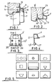
- a typical latch plate is illustrated in Figure 1 of the accompanying drawings. It comprises a housing 1, usually of die cast metal, having a recess 3 for the latch 5 of the lock 7 secured to door 17.
- the housing has an L-shaped face for mating around a corner of the door jamb 9.
- two screws 11 are employed to secure a flange part 13 to the door jamb and a third 15 to secure the other part of the latch plate to the jamb.
- the strength of the fixing is limited by the hold of the screws 11 and 15 and by the strength of the material (wood) of the door jamb in the area shaded as 16.
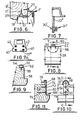
- a typical staple as seen from Figures 8 and 9 comprises a saddle like housing 50 having a bore 52 for receiving the end of the latch bolt (not illustrated) when extended into the locking position, and opposite flanges 54, with holes through which the securing screws 56 pass for screwing into the wood with the staple being secured on to the inner side of say a door frame 58.
- the size of the holes and hence the maximum diameter of the screws and usually therefore the length which can be employed is largely determined by aesthetics, with the aim seemingly being to minimise visible parts, even to the extent of effecting security of the fixing. With this arrangement, the threads are the only thing which holds the staple in position. Any forced entry acts directly along the line of the screw fixing, where resistance to pulling out must be least.
- extending the flange widthwise at or adjacent the end thereof, or intermediate its length, to give a step in at least one side of the flange produces a more secure fastening, in conjunction with the shallow recessing of the flange to fit flush with the frame rebate.
- a purpose formed recess is made in the jamb to accommodate the projection.
- the projection may be formed integrally with the flange, where the latch plate is a die casting, or it may be formed by fabrication - taking the form of a simple in-turned lip at the end of the flange, or in the form of a spigot secured to the flange by a headed screw received in a counterbored recess in the flange.
- the spigot may be secured by riveting or as a press fitting.
- the rebate has a depth from the edge of jamb equal to the thickness of the door and I find it most preferable to have the flange extend virtually the complete depth of the rebate. This enables longer and larger securing means to be employed. Since the flange terminates particularly closely to the edge of the jamb in known designs, the strength of the fixing can be increased by any increase in length of the flange. I find that a worthwhile increase in strength can be achieved if the location of the securing means or projection is at a distance equal to at least half the thickness of the door. A screw equal in length to the distance in from the edge of the jamb has been found suitable. Such a large screw, with or without the presence of a projection formed integrally with the flange, provides considerable resistance against pulling away of the latch plate.
- the projection provides a still better fastening especially where it has a depth greater than the space between the upright edge of the door and the rebate surface, since the plate cannot easily be dislodged from its position of location whilst the door is in place.
- the wood of the jamb has to fracture to allow the latch plate to be displaced, and by increasing the length of the flange, as I propose, means that a considerable amount of wood has to be fractured.
- My proposals for a more secure fastening find particular application to latch plates/staples for the lock/latch of a door or other opening closure.
- Such plates having two securing flanges disposed at right angles to one another so as to embrace around the carrier of the jamb.
- Each flange has holes for securing means in the form of screws which fix into the jamb.
- the present invention extends to a latch plate which can be provided with a flange which extends into the door receiving rebate and, by means of my proposal, is provided with locating and/or securing means, of or associated with said flange, projecting into the door jamb and located at a distance from the edge of the jamb sufficient to provide improved fracture resistance of the door jamb and hence a more secure fastening than with known latch plate fastening.
- One such application is to an improved staple for use with a latch bolt in which the staple has a flange or plate member which extends in a direction perpendicular to the axis of a bolt receiving bore of said plate member and provided with means for securing same to an abutment, typically a rebate of a door jamb on wall or other frame member.
- holes provided in the plate member serve to receive screws, threaded into the frame.
- said frame is recessed to receive said plate member flush with a rebated side face of the frame, and the plate is extended widthwise at a position intermediate its length or adjacent one end and inset from the edge of the frame so that said recess is correspondingly stepped to act as an abutment for said extension.
- a deeper projection into the frame is also contemplated, as outlined for the latch plate, although this is less preferable from the point of view of simplicity of manufacture and hence cost than the simple widthwise projection, although, bending a plate like member to give an inwardly directed lip is a possibility at reasonable cost.
- the length of the flange of the latch plate is greater than that of existing designs of latch plate, the increased amount of material between the securing means or projection(s) and the edge of the door jamb affords greeater security. That is to say a stronger fixing results because more material of the door jamb requires to be broken away to force entry through the door.
- the projection(s) may take various forms. In the case of the latch plate (where diecasting is involved) one or more cylindrical projections or a rectangular projection are considered to be the most preferred form for the flange projection.
- the holes for the fixing means may pass through the projection(s). I find a depth of between 6 mm and 15 mm to be suitable for the projection.
- a latch plate according to the present invention. It has a housing 1' with a recess 3' for receiving a latch of a lock, not illustrated.
- the housing has a first flange 13' and disposed substantially at right angles thereto, a second flange 21.
- the flanges 13' and 21 enable the latch plate to fit around the edge of a door jamb 9'. Fixing means in the nature of screws 11', 15 are employed to secure the latch plate to the jamb, and in addition the rebate 19' in the door jamb 9' to receive a door is grooved or cut away to accommodate the flange 13'.
- the flange 13' extends in length virtually the entire depth of the jamb rebate 19' from the inside edge 23 of thejamb. This enables holes 25 receiving fixing means 11' to be spaced a good distance from the edges 23 and thus ensures a large section of wood (material of the door jamb) between the screw 11' and the edge 23. For a typical door thickness of 42 mm, this distance can be of the order of 35 mm.
- the flange 13' also carries at least one projection 27 disposed adjacent the free end of the flange 13' and remote from the housing of the latch plate.
- the door jamb is provided with a complimentary shaped recess to accommodate the projection. This is formed whilst the groove is being formed to accommodate the flange 13'.
- the projection 27 serves to secure the latch plate more positively against pulling away.
- the holes are preferably counter sunk as illustrated at 29.
- the projection 27 of the embodiment illustrated in Figures 3 and 4 comprises a single cylindrical member (shown with an exagerated taper) which extends in a direction away from the external face of the flange 13'. This is a particular convenient form of projection for the purposes of installation of the latch plate as it simply requires a hold to be drilled in the required portion of the jamb.
- an elongated recess is formed to accommodate the projection.
- The. screw holes 25 would be formed in the projection.
- the screw holes 25 may be conveniently disposed in say the outer two projections.
- the use of a projection allows plenty of material for counter sinking the holes for larger screws.
- Additional screw holes 31 may be provided in the flange 13' in positions corresponding to those provided in existing known designs.
- the advantage of the present invention is in providing a larger flanger 13' so that securing means in the nature of the projection and/or screws is positioned further from the edge of the jamb so that the latch plate is therefore stronger and more resistant to being broken away from the jamb on forced entry.
- the latch plate of the present invention is a diecasting but alternative methods are also comtemplated for example by fabrication.
- the width AB may be variable between 50 mm and 100 mm to suit different widths of lock.
- the distance AD is designed to utilise the maximum amount of door frame available. For doors in common domestic use the distance AD would be 42 mm. Different lengths would be available to suit the common thicknesses of door in general use. It is not essential that the flange 13' occupy the complete depth of the door jamb but this is to be preferred to maximise the security.
- Figre 6 shows by way of example an alternative embodiment in which the flange extends to just over half the width of the rebate and the projection is located at approximately half the thickness of the door. This still provides improved strength overr the known construction. The construction of this embodiment is otherwise the same as that of Figures 2, 3 and 4 and corresponding reference numerals have been employed.
- the projection or projections of whatever design, would be accommodated within the area bounded by the letters A-B-C-D. It is preferred that the projections fit into the door frame by between 6 mm and 15 mm. It is preferred that the screw holes 25 be disposed approximately 9 mm from the line DC.
- the material of the flange is preferably sufficiently strong, with reinforcement if necessary, to resist fracture of the flange 13' within the strength limitations afforded by the material of the door jamb.
- Figure7 shows a further embodiment of latch plate in which the projection is formed by a spigot 31' which is secured to the flange 13" by means of a headed pin or stud 30'.
- the headed stud is received. in a counterbore in the flange 13" so that its head preferably lies flush with the exterior surface of the flange 13".
- the stud may have a thread for engaging with the spigot which has a complimentary thread. Alternatively, a press fit may be employed.
- the spigot may be of various designs such as any of the configurations described with reference to Figure 5.
- One or more studs may be employed as suits the shape of the spigot.
- the spigot may be riveted in place.
- the spigot is preferably of a metal or alloy, i.e. steel or brass. It will be appreciated that other methods of manufacturing and assembling the stud can be employed. For example modern adhesives may be used.
- Figure 7a shows a still further embodiment of latch plate in which the projection takes the form of a widthwise extension 40 to the flange 13''' with the flange 13"'received into the rebate of the door jamb, the projecting shoulders 42 abut against the wood of the door jamb so further resisting pull out of the latch plate.
- the staple 60 comprises a flange or plate member 62 which is fitted to the side of a door frame 64 in a door receiving rebate 66.
- a latch bolt is used for securing a door, and most often placed on the inside of the door/frame. Other applications are of course possible.
- the plate member 62 is elongate and has a hole 68 for receiving the bolt of a latch bolt.
- the plate projects from the inside face 70 of the frame 65 as consistant with flush fitting of a latch bolt where face 70 and inner door surface are in line.
- the plate of the invention is further advantageous in that it can be used where the face 70 projects beyond the door surface, a situation which cannot easily be accommodated with the known staple.
- the elongate plate has bores 72, preferably countersunk for receiving fixing screws 74. Because, the plate extends virtually the complete depth of the door rebate 66, the screws employed can be longer and even larger diameter, especially the one disposed remotely from the face 70. This gives rise to a secure fixing and because they are aligned with the axis of the bolt, they are effectively in shear and offer greater resistance to pulling out.
- the plate is recessed into the door rebate so as to be flush with the surface of the rebate 75.
- a cover 76 of arcuate configuration for fitting over the projecting end of the plate member and the bolt, when extended. This is largely cosmetic, to avoid snagging, but also serves to conceal the fact that the latch staple is anything other than a conventional one.
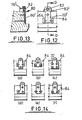
- FIG. 12 and 13 there is shown an embodiment of staple having several modifications, any one of which or any combination thereof may be applied to the embodiment already described.
- a plate member 60' which has a stepped side configuration, in the illustration, a T-shaped form is shown.
- the rebate 66 is recessed so that the surface of the plate is flush with the side face of the rebate.
- a corresponding T-shaped recess is formed in the rebate.
- the shoulders 84 can abut against shoulders of the recess.
- this widthwise projection serves to further increase resistance to pulling out.
- a further feature of the embodiment of Figures 12 and 13 is off-setting of the projecting end of the plate member at 80. This enables a cover member 76' to be fitted over and surrounding the projecting end preventing tampering with the end, and yet finishing flush with the rebate.
- the cover is arcuate, with a recess 82 open at one side, or a bore 82' as shown in dotted outline. The cover is secured in position by screws, not illustrated.
- a stepped front face for the member 80 could be arrived at by providing one long piece, positioned immediately adjacent the frame, and one shorter piece in front of it and preferably secured to the long piece, say as a lamination, thus providing a flush finish in conjunction with the cover member.
- a further alternative, where the staple is a fabrication or casting, is to have the cover(such as 76) formed integrally therewith.
- Figures 14 a to f show alternative configurations of plate member for the staple, all of which provide side ways projections and hence shoulders 84, for engaging a recess in the frame.
- the shoulders are spaced from the edge 70 of the frame to provide the necessary resistance against pulling out.
- a further alternative, not illustrated, is to provide an inturned lip, by bending the plate member, with the lip extending into a purpose formed groove in the frame.
- the securing plate of the staple extends perpendicular to the axis of the bolt, long screws and of thicker diameter can be employed without fear of splitting the door frame.
- the number of screws used to secure the plate in position can be one or more depending on the shape of the plate, but with extension widthwise a sufficient number can be used to ensure adequate fixing.
- a thick securing plate also gives rise to very good resistance to fracturing, even at the position where the sliding bolt engages; as it can be made of materials of high tensile strength, such as steel alloys.
- the cover may be made from plastics as it does not have to take any loading, and is conveniently made to compliment the rest of the sliding bolt assembly. A suitable decorative finish may be applied to the parts.
- the staple of the invention is simply installed, inexpensive top produce, and yet gives improved security.
Landscapes
- Lock And Its Accessories (AREA)
- Securing Of Glass Panes Or The Like (AREA)
Applications Claiming Priority (4)
| Application Number | Priority Date | Filing Date | Title |
|---|---|---|---|
| GB8604189 | 1986-02-20 | ||
| GB868604189A GB8604189D0 (en) | 1986-02-20 | 1986-02-20 | Fastening means for doors &c |
| GB868619395A GB8619395D0 (en) | 1986-08-08 | 1986-08-08 | Fastening doors &c |
| GB8619395 | 1986-08-08 |
Publications (2)
| Publication Number | Publication Date |
|---|---|
| EP0234784A2 true EP0234784A2 (de) | 1987-09-02 |
| EP0234784A3 EP0234784A3 (de) | 1988-01-13 |
Family
ID=26290374
Family Applications (1)
| Application Number | Title | Priority Date | Filing Date |
|---|---|---|---|
| EP87301071A Withdrawn EP0234784A3 (de) | 1986-02-20 | 1987-02-06 | Schliessbeschlag für Türen oder degleichen |
Country Status (1)
| Country | Link |
|---|---|
| EP (1) | EP0234784A3 (de) |
Cited By (1)
| Publication number | Priority date | Publication date | Assignee | Title |
|---|---|---|---|---|
| GB2288633A (en) * | 1994-04-18 | 1995-10-25 | David Middlehurst | Keep for a lock |
Family Cites Families (5)
| Publication number | Priority date | Publication date | Assignee | Title |
|---|---|---|---|---|
| DE218660C (de) * | ||||
| GB1051316A (de) * | 1900-01-01 | |||
| US3767245A (en) * | 1972-03-21 | 1973-10-23 | J Keefe | Jamb dead bolt plate |
| GB1471896A (en) * | 1975-07-15 | 1977-04-27 | Crompton Nettlefold Stenman | Staples for use with hasps |
| FR2457363A1 (fr) * | 1979-05-22 | 1980-12-19 | Chauvat & Sofranq Reunis | Gache de serrure pour huisserie bois, et serrure comportant une telle gache |
-
1987
- 1987-02-06 EP EP87301071A patent/EP0234784A3/de not_active Withdrawn
Cited By (2)
| Publication number | Priority date | Publication date | Assignee | Title |
|---|---|---|---|---|
| GB2288633A (en) * | 1994-04-18 | 1995-10-25 | David Middlehurst | Keep for a lock |
| GB2288633B (en) * | 1994-04-18 | 1998-04-01 | David Middlehurst | Improvements in and relating to locks |
Also Published As
| Publication number | Publication date |
|---|---|
| EP0234784A3 (de) | 1988-01-13 |
Similar Documents
| Publication | Publication Date | Title |
|---|---|---|
| US4416087A (en) | Door frame reinforcer | |
| US4690445A (en) | Security striker plate | |
| US8132832B2 (en) | Door jamb reinforcing system | |
| US4802701A (en) | Anchor latch | |
| US4550939A (en) | Security strike assembly | |
| US5024475A (en) | Strengthening door jamb | |
| US4861082A (en) | Door security system | |
| US5074606A (en) | Door security system | |
| US4809400A (en) | Security hardware for doors | |
| US5456507A (en) | Deadbolt strike plate | |
| US4865370A (en) | Keeper for deadbolt locks | |
| US6598350B1 (en) | Doorjamb reinforcement plates | |
| US6837527B1 (en) | Strike plate assembly for a dead bolt | |
| US6430876B1 (en) | Door hardware interconnected with overlying reinforcement plate | |
| IE57539B1 (en) | A reinforcing device for a door | |
| US6679019B2 (en) | Method and apparatus for reinforcing a door | |
| US20030159361A1 (en) | Reinforced door jamb | |
| US7165793B2 (en) | Door jamb security plate | |
| US6050114A (en) | Latch assembly of padlock for sliding doors | |
| US5934719A (en) | External lock assembly for sliding doors and the like cooperating with a tubular frame mounted element | |
| EP0234784A2 (de) | Schliessbeschlag für Türen oder degleichen | |
| US4627651A (en) | Safety locking device for doors | |
| US20030057718A1 (en) | Striker plate for residential doors | |
| US4656691A (en) | Door hinge with pin member for engaging wall structure | |
| US6076866A (en) | Locking fitting for sliding leaf and burglary-safe device for such a fitting |
Legal Events
| Date | Code | Title | Description |
|---|---|---|---|
| PUAI | Public reference made under article 153(3) epc to a published international application that has entered the european phase |
Free format text: ORIGINAL CODE: 0009012 |
|
| AK | Designated contracting states |
Kind code of ref document: A2 Designated state(s): DE FR GB IT |
|
| PUAL | Search report despatched |
Free format text: ORIGINAL CODE: 0009013 |
|
| AK | Designated contracting states |
Kind code of ref document: A3 Designated state(s): DE FR GB IT |
|
| STAA | Information on the status of an ep patent application or granted ep patent |
Free format text: STATUS: THE APPLICATION IS DEEMED TO BE WITHDRAWN |
|
| 18D | Application deemed to be withdrawn |
Effective date: 19880714 |