EP0234698B1 - Steel sheets for painting and a method of producing the same - Google Patents
Steel sheets for painting and a method of producing the same Download PDFInfo
- Publication number
- EP0234698B1 EP0234698B1 EP87300321A EP87300321A EP0234698B1 EP 0234698 B1 EP0234698 B1 EP 0234698B1 EP 87300321 A EP87300321 A EP 87300321A EP 87300321 A EP87300321 A EP 87300321A EP 0234698 B1 EP0234698 B1 EP 0234698B1
- Authority
- EP
- European Patent Office
- Prior art keywords
- steel sheet
- roll
- mountain
- work roll
- dulled
- Prior art date
- Legal status (The legal status is an assumption and is not a legal conclusion. Google has not performed a legal analysis and makes no representation as to the accuracy of the status listed.)
- Expired - Lifetime
Links
- 229910000831 Steel Inorganic materials 0.000 title claims description 122
- 239000010959 steel Substances 0.000 title claims description 122
- 238000000034 method Methods 0.000 title claims description 50
- 238000010422 painting Methods 0.000 title description 22
- 238000005096 rolling process Methods 0.000 claims description 52
- 230000003746 surface roughness Effects 0.000 claims description 44
- 238000012546 transfer Methods 0.000 claims description 9
- 239000000463 material Substances 0.000 description 21
- 239000010410 layer Substances 0.000 description 13
- 239000002184 metal Substances 0.000 description 13
- 229910052751 metal Inorganic materials 0.000 description 13
- 239000011248 coating agent Substances 0.000 description 12
- 238000000576 coating method Methods 0.000 description 12
- 230000001788 irregular Effects 0.000 description 9
- 239000010960 cold rolled steel Substances 0.000 description 8
- 238000009826 distribution Methods 0.000 description 8
- 238000002474 experimental method Methods 0.000 description 6
- 238000000137 annealing Methods 0.000 description 5
- 239000007789 gas Substances 0.000 description 5
- 238000012360 testing method Methods 0.000 description 5
- 239000010687 lubricating oil Substances 0.000 description 4
- 239000003973 paint Substances 0.000 description 4
- 239000010953 base metal Substances 0.000 description 3
- 230000015572 biosynthetic process Effects 0.000 description 3
- 238000007664 blowing Methods 0.000 description 3
- 238000007598 dipping method Methods 0.000 description 3
- 238000007591 painting process Methods 0.000 description 3
- 238000012545 processing Methods 0.000 description 3
- 238000005406 washing Methods 0.000 description 3
- XLYOFNOQVPJJNP-UHFFFAOYSA-N water Substances O XLYOFNOQVPJJNP-UHFFFAOYSA-N 0.000 description 3
- 229910019142 PO4 Inorganic materials 0.000 description 2
- HCHKCACWOHOZIP-UHFFFAOYSA-N Zinc Chemical compound [Zn] HCHKCACWOHOZIP-UHFFFAOYSA-N 0.000 description 2
- 230000000052 comparative effect Effects 0.000 description 2
- 230000003247 decreasing effect Effects 0.000 description 2
- 238000005238 degreasing Methods 0.000 description 2
- 238000010894 electron beam technology Methods 0.000 description 2
- 238000004519 manufacturing process Methods 0.000 description 2
- NBIIXXVUZAFLBC-UHFFFAOYSA-K phosphate Chemical compound [O-]P([O-])([O-])=O NBIIXXVUZAFLBC-UHFFFAOYSA-K 0.000 description 2
- 239000010452 phosphate Substances 0.000 description 2
- 229910052725 zinc Inorganic materials 0.000 description 2
- 239000011701 zinc Substances 0.000 description 2
- MYMOFIZGZYHOMD-UHFFFAOYSA-N Dioxygen Chemical compound O=O MYMOFIZGZYHOMD-UHFFFAOYSA-N 0.000 description 1
- 239000003795 chemical substances by application Substances 0.000 description 1
- 239000011247 coating layer Substances 0.000 description 1
- 238000005097 cold rolling Methods 0.000 description 1
- 238000007796 conventional method Methods 0.000 description 1
- 230000001419 dependent effect Effects 0.000 description 1
- 229910001882 dioxygen Inorganic materials 0.000 description 1
- 238000001035 drying Methods 0.000 description 1
- 230000000694 effects Effects 0.000 description 1
- 238000009713 electroplating Methods 0.000 description 1
- 238000011156 evaluation Methods 0.000 description 1
- 229910052739 hydrogen Inorganic materials 0.000 description 1
- 230000001678 irradiating effect Effects 0.000 description 1
- 238000005461 lubrication Methods 0.000 description 1
- 238000005259 measurement Methods 0.000 description 1
- 229910052757 nitrogen Inorganic materials 0.000 description 1
- 238000001579 optical reflectometry Methods 0.000 description 1
- 229910052698 phosphorus Inorganic materials 0.000 description 1
- 238000005498 polishing Methods 0.000 description 1
- 239000000843 powder Substances 0.000 description 1
- 238000003908 quality control method Methods 0.000 description 1
- 229920006395 saturated elastomer Polymers 0.000 description 1
- 238000010008 shearing Methods 0.000 description 1
- 239000000758 substrate Substances 0.000 description 1
- 229910052717 sulfur Inorganic materials 0.000 description 1
Images


Classifications
-
- C—CHEMISTRY; METALLURGY
- C21—METALLURGY OF IRON
- C21D—MODIFYING THE PHYSICAL STRUCTURE OF FERROUS METALS; GENERAL DEVICES FOR HEAT TREATMENT OF FERROUS OR NON-FERROUS METALS OR ALLOYS; MAKING METAL MALLEABLE, e.g. BY DECARBURISATION OR TEMPERING
- C21D9/00—Heat treatment, e.g. annealing, hardening, quenching or tempering, adapted for particular articles; Furnaces therefor
- C21D9/46—Heat treatment, e.g. annealing, hardening, quenching or tempering, adapted for particular articles; Furnaces therefor for sheet metals
-
- B—PERFORMING OPERATIONS; TRANSPORTING
- B21—MECHANICAL METAL-WORKING WITHOUT ESSENTIALLY REMOVING MATERIAL; PUNCHING METAL
- B21B—ROLLING OF METAL
- B21B1/00—Metal-rolling methods or mills for making semi-finished products of solid or profiled cross-section; Sequence of operations in milling trains; Layout of rolling-mill plant, e.g. grouping of stands; Succession of passes or of sectional pass alternations
- B21B1/22—Metal-rolling methods or mills for making semi-finished products of solid or profiled cross-section; Sequence of operations in milling trains; Layout of rolling-mill plant, e.g. grouping of stands; Succession of passes or of sectional pass alternations for rolling plates, strips, bands or sheets of indefinite length
- B21B1/227—Surface roughening or texturing
-
- B—PERFORMING OPERATIONS; TRANSPORTING
- B21—MECHANICAL METAL-WORKING WITHOUT ESSENTIALLY REMOVING MATERIAL; PUNCHING METAL
- B21B—ROLLING OF METAL
- B21B1/00—Metal-rolling methods or mills for making semi-finished products of solid or profiled cross-section; Sequence of operations in milling trains; Layout of rolling-mill plant, e.g. grouping of stands; Succession of passes or of sectional pass alternations
- B21B1/22—Metal-rolling methods or mills for making semi-finished products of solid or profiled cross-section; Sequence of operations in milling trains; Layout of rolling-mill plant, e.g. grouping of stands; Succession of passes or of sectional pass alternations for rolling plates, strips, bands or sheets of indefinite length
-
- C—CHEMISTRY; METALLURGY
- C21—METALLURGY OF IRON
- C21D—MODIFYING THE PHYSICAL STRUCTURE OF FERROUS METALS; GENERAL DEVICES FOR HEAT TREATMENT OF FERROUS OR NON-FERROUS METALS OR ALLOYS; MAKING METAL MALLEABLE, e.g. BY DECARBURISATION OR TEMPERING
- C21D8/00—Modifying the physical properties by deformation combined with, or followed by, heat treatment
- C21D8/02—Modifying the physical properties by deformation combined with, or followed by, heat treatment during manufacturing of plates or strips
- C21D8/04—Modifying the physical properties by deformation combined with, or followed by, heat treatment during manufacturing of plates or strips to produce plates or strips for deep-drawing
- C21D8/0421—Modifying the physical properties by deformation combined with, or followed by, heat treatment during manufacturing of plates or strips to produce plates or strips for deep-drawing characterised by the working steps
- C21D8/0436—Cold rolling
-
- C—CHEMISTRY; METALLURGY
- C21—METALLURGY OF IRON
- C21D—MODIFYING THE PHYSICAL STRUCTURE OF FERROUS METALS; GENERAL DEVICES FOR HEAT TREATMENT OF FERROUS OR NON-FERROUS METALS OR ALLOYS; MAKING METAL MALLEABLE, e.g. BY DECARBURISATION OR TEMPERING
- C21D9/00—Heat treatment, e.g. annealing, hardening, quenching or tempering, adapted for particular articles; Furnaces therefor
- C21D9/38—Heat treatment, e.g. annealing, hardening, quenching or tempering, adapted for particular articles; Furnaces therefor for roll bodies
-
- B—PERFORMING OPERATIONS; TRANSPORTING
- B21—MECHANICAL METAL-WORKING WITHOUT ESSENTIALLY REMOVING MATERIAL; PUNCHING METAL
- B21B—ROLLING OF METAL
- B21B1/00—Metal-rolling methods or mills for making semi-finished products of solid or profiled cross-section; Sequence of operations in milling trains; Layout of rolling-mill plant, e.g. grouping of stands; Succession of passes or of sectional pass alternations
- B21B1/22—Metal-rolling methods or mills for making semi-finished products of solid or profiled cross-section; Sequence of operations in milling trains; Layout of rolling-mill plant, e.g. grouping of stands; Succession of passes or of sectional pass alternations for rolling plates, strips, bands or sheets of indefinite length
- B21B2001/228—Metal-rolling methods or mills for making semi-finished products of solid or profiled cross-section; Sequence of operations in milling trains; Layout of rolling-mill plant, e.g. grouping of stands; Succession of passes or of sectional pass alternations for rolling plates, strips, bands or sheets of indefinite length skin pass rolling or temper rolling
-
- B—PERFORMING OPERATIONS; TRANSPORTING
- B21—MECHANICAL METAL-WORKING WITHOUT ESSENTIALLY REMOVING MATERIAL; PUNCHING METAL
- B21B—ROLLING OF METAL
- B21B2261/00—Product parameters
- B21B2261/14—Roughness
-
- B—PERFORMING OPERATIONS; TRANSPORTING
- B21—MECHANICAL METAL-WORKING WITHOUT ESSENTIALLY REMOVING MATERIAL; PUNCHING METAL
- B21B—ROLLING OF METAL
- B21B2267/00—Roll parameters
- B21B2267/10—Roughness of roll surface
-
- C—CHEMISTRY; METALLURGY
- C21—METALLURGY OF IRON
- C21D—MODIFYING THE PHYSICAL STRUCTURE OF FERROUS METALS; GENERAL DEVICES FOR HEAT TREATMENT OF FERROUS OR NON-FERROUS METALS OR ALLOYS; MAKING METAL MALLEABLE, e.g. BY DECARBURISATION OR TEMPERING
- C21D8/00—Modifying the physical properties by deformation combined with, or followed by, heat treatment
- C21D8/02—Modifying the physical properties by deformation combined with, or followed by, heat treatment during manufacturing of plates or strips
- C21D8/04—Modifying the physical properties by deformation combined with, or followed by, heat treatment during manufacturing of plates or strips to produce plates or strips for deep-drawing
- C21D8/0478—Modifying the physical properties by deformation combined with, or followed by, heat treatment during manufacturing of plates or strips to produce plates or strips for deep-drawing involving a particular surface treatment
-
- Y—GENERAL TAGGING OF NEW TECHNOLOGICAL DEVELOPMENTS; GENERAL TAGGING OF CROSS-SECTIONAL TECHNOLOGIES SPANNING OVER SEVERAL SECTIONS OF THE IPC; TECHNICAL SUBJECTS COVERED BY FORMER USPC CROSS-REFERENCE ART COLLECTIONS [XRACs] AND DIGESTS
- Y10—TECHNICAL SUBJECTS COVERED BY FORMER USPC
- Y10S—TECHNICAL SUBJECTS COVERED BY FORMER USPC CROSS-REFERENCE ART COLLECTIONS [XRACs] AND DIGESTS
- Y10S428/00—Stock material or miscellaneous articles
- Y10S428/922—Static electricity metal bleed-off metallic stock
- Y10S428/923—Physical dimension
- Y10S428/924—Composite
- Y10S428/925—Relative dimension specified
-
- Y—GENERAL TAGGING OF NEW TECHNOLOGICAL DEVELOPMENTS; GENERAL TAGGING OF CROSS-SECTIONAL TECHNOLOGIES SPANNING OVER SEVERAL SECTIONS OF THE IPC; TECHNICAL SUBJECTS COVERED BY FORMER USPC CROSS-REFERENCE ART COLLECTIONS [XRACs] AND DIGESTS
- Y10—TECHNICAL SUBJECTS COVERED BY FORMER USPC
- Y10T—TECHNICAL SUBJECTS COVERED BY FORMER US CLASSIFICATION
- Y10T428/00—Stock material or miscellaneous articles
- Y10T428/12—All metal or with adjacent metals
- Y10T428/12389—All metal or with adjacent metals having variation in thickness
-
- Y—GENERAL TAGGING OF NEW TECHNOLOGICAL DEVELOPMENTS; GENERAL TAGGING OF CROSS-SECTIONAL TECHNOLOGIES SPANNING OVER SEVERAL SECTIONS OF THE IPC; TECHNICAL SUBJECTS COVERED BY FORMER USPC CROSS-REFERENCE ART COLLECTIONS [XRACs] AND DIGESTS
- Y10—TECHNICAL SUBJECTS COVERED BY FORMER USPC
- Y10T—TECHNICAL SUBJECTS COVERED BY FORMER US CLASSIFICATION
- Y10T428/00—Stock material or miscellaneous articles
- Y10T428/12—All metal or with adjacent metals
- Y10T428/12993—Surface feature [e.g., rough, mirror]
Definitions
- This invention relates to steel sheets suitable for being painted such as cold rolled steel sheets, zinc hot dipped or electroplated steel sheets, which are subjected to a forming operation, such as press forming, before or after a painting process in the production of an outer panel for automobiles or a decorative outer plate for electric appliances, and to a method of producing the same.
- the cold rolled thin steel sheet is usually subjected to degreasing, annealing and temper rolling in this order.
- the temper rolling is to improve the galling resistance in the press forming by conducting a light rolling through work rolls having a dulled surface to give a proper surface roughness to the steel sheet surface.
- the finish feeling after painting on vehicle body in passenger cars and trucks is a very important quality control item because the height in synthetic quality of automobile can directly be appealed to the eye of the user as a good finish quality.
- the distinctness of image on the painted surface is dependent upon the kind of paint and the painting process but is strongly influenced by the rough surface of the steel sheet as a substrate. That is, when the ratio of flat portion occupied in the steel sheet surface is small and the unevenness is high, the ratio of flat portion occupied in the painted surface becomes small and the unevenness becomes larger, and consequently the irregular reflection of light is caused to damage the glossiness and also the image strain is produced to deteriorate the image clarity, so that the distinctness of image is degraded.
- the roughness of the steel sheet surface is frequently represented as a center-line average roughness Ra. Further, it is known that as the center-line average roughness Ra becomes larger, the amplitude between mountain portion and valley portion becomes large and hence the unevenness of the painted surface becomes large and consequently the distinctness of image is degraded.
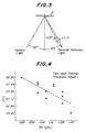
- DOI value As a method for evaluating the distinctness of image, there have been developed various systems. Among them, a value measured by means of a Dorigon meter made by Hunter Associates Laboratory or a so-called DOI value is most usually used.
- the relation between the DOI value indicating the distinctness of image and the center-line average roughness Ra is shown in Figs. 4 and 5.
- Fig. 4 is a case that a two-layer coating of 55 ⁇ m in thickness is applied to a steel sheet temper rolled with a roll dulled through the conventional shot blast process
- Fig. 5 is a case that a three-layer coating of 85 ⁇ m in thickness is applied to the same steel sheet as mentioned above. It can be understood from Figs. 4 and 5 that as the center-line average roughness Ra becomes large, the DOI value becomes small to degrade the distinctness of image.
- the steel sheet When the steel sheet is subjected to a temper rolling with work rolls dulled through the conventional shot blast process or discharge working process, it exhibits a rough surface comprised of irregular mountain portions and valley portions as previously mentioned, wherein the flat portion is very little.
- the painting is applied to the steel sheet having such irregular mountain and valley portions, since the coating is formed along the slopes of the mountain and valley portions, the ratio of flat portion occupied in the painted surface becomes small as shown, for example, in Fig. 33 being mentioned later and consequently the distinctness of image is degraded. In the conventional shot blast process or discharge working process, such a problem can not be avoided, so that it is very difficult to provide a sufficiently improved distinctness of image on the painted surface.
- the invention provides steel sheets having a distinctness of image considerably better than that of conventional sheets without the necessity of changing the usually used paint and the painting process.
- a method of producing a steel sheet suitable for being painted which comprises subjecting the surface of a work roll for temper rolling to a dulling of its surface by means of a high density energy source so as to form craters having a mean diameter d, and then temper rolling a steel sheet with a pair of work rolls, at least one of which is the dulled work roll produced in the foregoing manner, at a draft ( ⁇ ) of not less than 0.3% to transfer the pattern of the dulled work roll on to the surface of the steel sheet, whereby there is obtained a steel sheet characterized in having a center-line average surface roughness Ra within the range of 0.3 to 3.0 pm and a microscopic shape constituting said surface roughness which is comprised of trapezoidal mountain portions having a flat top surface, groove-like valley portions formed so as to surround a whole or a part of the mountain portion and middle flat portions formed between the mountain portions outside of the valley portion so as to be higher than the bottom of the valley portion and lower than or equal to the top
- the paintable steel sheets of the invention can be produced by subjecting the surface of a work roll for temper rolling to a dulling of its surface pattern effected by means of a high density energy source, and then temper rolling a steel sheet with a pair of work rolls, at least one of which is the dulled work roll produced in the foregoing manner, at a draft ( ⁇ ) of not less than 0.3% to transfer the pattern of the dulled work roll onto the surface of the steel sheet.
- the high density energy source it is preferred to use a laser but alternatively plasma or an electron beam may be used.
- cold rolled steel sheets are usually used, but surface-treated steel sheets, which are previously subjected to zinc hot dipping or electroplating, as well as hot rolled steel sheets may also be used.
- a work roll for temper rolling is dulled through a high density energy source, e.g. a laser as follows.
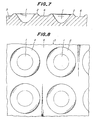
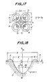
- FIG. 6 sectionally shows a part of the dulled roll surface, wherein numeral 1 is a crater-like concave portion (hereinafter referred to as a crater simply) formed on a surface of a work roll 3.
- the fused base metal of the roll upheaves upward from the surface level 6 of the roll 3 in the form of ring around the crater 1 to form a flange-like upheaved portion 2 (hereinafter referred to as a flange simply).
- the inner wall layer of the crater 1 inclusive of the flange 2 is a heat-affected zone to a base metal structure 4 of the roll.
- the depth and diameter of the crater 1 formed on the roll surface through laser pulse are determined by the intensity of energy in the incident laser and the projecting time, which gives a quantity defining a roughness corresponding to surface roughness Ra in the work roll dulled through the conventional shot blast process.
- the base metal of the roll heated by laser instantly changes into a metallic vapor due to large energy density of irradiated laser.
- the fused metal is blown away from the roll surface by the generated vapor pressure to form the crater 1, while the blown fused metal again adheres to the circumference of the crater 1 to form the flange 2 surrounding the crater 1.
- Such a series of actions are more efficiently performed by blowing an auxiliary gas such as oxygen gas or the like to the reaction point.
- the above craters 1 are regularly formed by regularly irradiating the laser pulse while rotating or axially moving the work roll, whereby the surface of the roll is rendered into a rough state through the gathering of these formed craters.
- the rough state of the roll surface is shown in Figs. 7 and 8.
- a portion located between the adjacent craters 1 outside the flange 2 is a flat surface 6 corresponding to the original roll surface.
- the mutual distance between the adjacent craters can be adjusted by controlling the frequency of laser pulse in relation to the rotating speed of the roll in the rotating direction of the roll and by controlling the pitch of moving the irradiation position of the laser in the axial direction of the roll.
- a steel sheet such as a cold rolled steel sheet after annealing or the like is rolled at a light draft at the temper rolling step using the work roll dulled through laser as mentioned above, whereby the dull pattern formed on the surface of the work roll is transferred to the surface of the work roll is transferred to the surface of the steel sheet to thereby give a rough surface to the steel sheet.
- a top surface 8 of the upheaved steel sheet inside the crater 1 becomes flat likewise the original steel sheet surface, while that portion 9 of the steel sheet which is pushed by the flat portion 6 between the adjacent craters 1 outside the flange 2 in the roll 3 is flat as it is, and the former flat surface 8 is higher than or equal to the latter flat surface 9. Therefore, as shown in Figs.
- the microscopic shape of surface roughness in the steel sheet 7 after the temper rolling is comprised of trapezoidal mountain portions 10 having a flat top surface 8, groove-like valley portions 11 formed so as to surround the mountain portions, and middle flat portions 9 formed between the adjoining mountain portions 10 outside the valley portion 11 so as to be higher than the bottom of the valley portion 11 and lower than or equal to the top surface of the mountain portion 10.
- the ratio of flat portions comprising the top surface 8 of the mountain portion 10 and the middle flat portion 9 becomes larger in the surface of steel sheet after the temper rolling, while the ratio of slope 13 between the mountain portion 10 and the valley portion 11 becomes principally small.
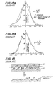
- the roughness of the roll surface has various mountain heights similar to normal distribution as shown in Fig. 12a or 12b.
- the surface roughness profile of the roll 3 is synthesized with the surface roughness profile of the original steel sheet 7 by the encroach of mountains in the roll 3 on the surface of the steel sheet 7 as shown in Fig. 13, so that the ratio of slopes between the mountain and the valley becomes principally larger in the steel sheet 7 after the temper rolling.
- the structure and formation step of surface roughness profile by the conventional technique are entirely different from those in the steel sheet temper rolled with the work roll dulled through the laser process.
- Fig. 14a an inclination angle distribution of surface roughness in the steel sheet after the temper rolling using the work dulled through the conventional shot blast process.
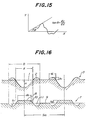
- the definition of the inclination angle (6) is illustrated in Fig. 15. Since the DOI value indicating the distinctness of image is represented by a ratio of the scattered light at a reflective angle of 30° ⁇ 0.3° to the specular reflected light as previously mentioned, the flatness can be judged to be good when the ratio of valley portion having ⁇ as an inclination angle with tolerance of ⁇ 0.3° is large. In case of Fig. 14a, however, the occupation ratio (W 2o ) of tan ⁇ ⁇ 0.3° is only 14%.
- the area ratio ⁇ of flat portions is represented by a sum of area occupation ratio ⁇ 1 of flat top surface 8 of mountain portion 10 and area occupation ratio ⁇ 2 of middle flat portion 9, i.e.
- the value of ⁇ 1 varies in accordance with the draft in the temper rolling, because the degree of flowing metal of steel sheet into the crater 1 changes with the change of the draft and hence the diameter do of top surface 8 of mountain portion 10 changes.
- the value of ⁇ 2 is constant in accordance with the value of Sm/D.
- ⁇ 1 is determined by the following equation (3), and do is constantly related to d as shown in the following equation (4), and ⁇ 2 is determined in accordance with the value of Sm/D by the following equation (5):
- a ratio of height h 2 of mountain portion 10 transferred onto the steel sheet surface through the crater. to depth H of the crater 1 can be called as a roughness transfer ratio.
- the depth H of crater 1 is 1, so that the roughness transfer ratio is h 2 /1 or h 2 .
- An SPCC steel sheet having a roughness Ra of 0.38 pm and a thickness of 0.32 mm was temper rolled at various drafts A by using a work roll having a diameter of 200 mm and an Hs hardness of 94, which was dulled to Ra of 3.54 pm through the laser process, as a roll for temper rolling.
- the results are shown in Fig. 19.
- the roughness transfer ratio h 2 /l linearly increases when the draft ⁇ rises up to about 1.5% and is saturated when the draft ⁇ exceeds 1.8%.
- the draft ⁇ in temper rolling influences on ⁇ , but when A is too small, the temper rolling operation itself is unstable and it is difficult to conduct the dulling of the steel sheet surface.
- the inventor has found that the dulling is possible when the draft in temper rolling is not less than 0.3%. Therefore, the lower limit of the draft ⁇ is 0.3%.
- the DOI value increases as ⁇ becomes large, and hence the distinctness of image becomes good.
- DOI value is not less than 94% for giving satisfactory high-grade feeling to the coating on the vehicle body.
- ⁇ is not less than 35%.
- ⁇ is sufficient to be not less than 20%. Therefore, the lower limit of ⁇ is 20%.
- the dimensions such as D, Sm, H and the like in the surface roughness profile of the roll defined in the above item [3] can be changed by adjusting the dulling conditions of work roll for temper rolling through laser such as revolution number of roll, frequency of laser pulse, output of laser, speed of feeding laser irradiation point and laser irradiation time, or the blowing condition of auxiliary gas such as 0 2 gas or the like as seen from the above.
- the surface of the work roll has a flange width a of about 20-40 pm and a flange height h, of about 5-30 pm.
- Figs. 22a to 22c In the surface roughness profile formed on the steel sheet, three patterns as shown in Figs. 22a to 22c are obtained in accordance with the value of Sm/D. That is, when Sm/D is 1, the adjoining valley portions 11 just come into contact with each other as shown in Fig. 22a. When Sm/D>1, the adjoining valley portions 11 separate away from each other as shown in Fig. 22b. Further, when Sm/D ⁇ 1, the adjoining valley portions 11 overlap with each other as shown in Fig. 22c.
- various patterns of the surface roughness profile can be obtained by changing the value of Sm/D.
- work rolls for temper rolling having various values of Sm/D were prepared through the laser process, and then the formation of dull pattern on the cold rolled steel sheet after annealing was performed by temper rolling at a proper draft with these work rolls. Thereafter, the dulled steel sheet was subjected to a press forming test and a painting test, from which the following knowledges were obtained.
- the size of the flange formed on the roll surface through the laser process i.e. width a and height h, are related to a course that a part of metal in the crater portion fused by laser upheaves at its circumference and is resolidified.
- a and h also become large. That is, when D is large, a capacity of reserving a lubricating oil in the press forming and a capacity of trapping exfoliated metallic debris become large, which is significant for preventing the galling.
- the flanges are formed on the roll surface around the craters by blowing the auxiliary gas to upheave metal fused by laser onto the roll surface.
- the flange does not necessarily take a circle due to slight ununiformity of auxiliary gas flowing distribution and fluctuation of flowing rate, i.e. a part of the flange is cut off. Therefore, in the surface of the steel sheet temper rolled by the work roll having the above flanges of irregular form, a part of the mountain portion is not surrounded by the valley portion, which results in the increase of ⁇ to improve the distinctness of image.
- the same experiment as described above was made with respect to such a steel sheet to obtain results (•, A and #) as shown in Fig. 26, therb is no great difference in the press formability between the case that the mountain portion is completely surrounded by the valley portion and the case that the mountain portion is partially surrounded by the valley portion.
- the upper limit of Sm/D is 3.0
- the upper limit of area ratio ⁇ is 95%
- the upper limit of (Sm-D) is less than 450 pm in order to provide steel sheets causing no galling and having a good press formability.
- Sm/D exceeds 1
- the adjoining flanges 2 separate away from each other as shown in Fig. 28a
- Sm/D is less than 1
- the adjoining flanges 2 overlap with each other.
- the lower limit of Sm/D should be 0.85.
- the flat top surface 8 of mountain portion 10 constituting the microscopic surface roughness profile of steel sheet is a plane bearing the press load in the press forming, which corresponds to a so-called load bearing area.
- the upper limit of do should be 500 pm.
- the mountain portion 10 is apt to be broken by compressive stress and shearing stress in the press forming to produce a large amount of metallic debris therefrom, which is also liable to cause the galling.
- the inventor has confirmed that the galling is apt to be caused when do is less than 30 pm.
- the value of D is necessarily small, so that the value of Sm itself should be small in order to satisfy Sm/D ⁇ 3.0 as previously mentioned on the item [7] when do is made small. That is, the distance between the craters in the roll should be small.
- the revolution number of roll is extremely decreased in the laser irradiation or the frequency of laser pulse is considerably increased, which becomes disadvantageous in economy. From these reasons, the diameter do of the top surface 8 in mountain portion 10 should be not less than 30 ⁇ m.
- the diameter do of the top surface 8 is sufficient within a range of 30-500 ⁇ m on average.
- the mountain portions 10 are formed by temper rolling with the work roll dulled through the high density energy source such as laser, the plan form of the flat top surface 8 in the mountain portion 10 is not always true circle and frequently becomes oblong or irregular.
- the mean value of major axis in top surfaces is not more than 500 pm and the mean value of minor axis in top surfaces is not less than 30 ⁇ m.
- the maximum major axis in all top surfaces is not more than 500 pm and the minimum minor axis in all top surfaces is not less than 30 pm.
- Ra should be within a range of 0.3-3.0 pm.
- Ra is not more than 3.0 ⁇ m in order to provide a DOI value of not less than 94 as a distinctness of image.
- the microscopic surface roughness profile of steel sheet satisfies the following conditions:
- a cold rolled steel sheet of 0.8 mm in thickness which was produced by cold rolling a steel sheet containing C: 0.04%, Mn: 0.2%, P: 0.02%, S: 0.015%, N: 0.003% and 0: 0.005% at a draft of 69.2% and annealing in a box annealing furnace.
- a work roll for temper rolling there were provided a roll dulled through a laser pulse process, a roll dulled through the conventional shot blast process, a roll dulled through the conventional discharge working process, and a bright roll not diluted. Then, the cold rolled steel sheet was temper rolled with this work roll at a draft A ranging from 0.5% to 2.5%.
- the surface roughness Ra of the bright roll was 0.15 pm, while the surface roughness Ra of the dulled roll was within a range of 1.1-5.6 ⁇ m.
- As the surface roughness profile of the work roll dulled through the laser pulse process there were particularly provided sample A with 0.85 ⁇ Sm/D ⁇ 1.7, Sm-D ⁇ 280 ⁇ m, 50 ⁇ m ⁇ d ⁇ 500 ⁇ m, 35 ⁇ m ⁇ H ⁇ 120 ⁇ m and h 1 ⁇ 1/3H, and a sample B with 1.7 ⁇ Sm/D ⁇ 3.0, Sm-D ⁇ 450 ⁇ m, 50 ⁇ m ⁇ d ⁇ 500 ⁇ m, 35 ⁇ m ⁇ H ⁇ 120 ⁇ m and h 1 ⁇ 1/3H.
- the surface roughness profile on sample A had 0.85 ⁇ Sm/ D ⁇ 1.7, Sm-D ⁇ 280 ⁇ m and 30 ⁇ m ⁇ d ⁇ 500 ⁇ m, and that on sample B had 1.7 ⁇ Sm/D ⁇ 3.0, Sm-D ⁇ 450 ⁇ m and 30 ⁇ m ⁇ d ⁇ 500 pm.
- the temper rolled steel sheet was subjected to a phosphating treatment under the following conditions:
- DOI value of the painted surface was measured by means of a Dorigon meter.
- LD material is a steel sheet temper rolled with the work roll dulled through the laser pulse process
- EDT material is a steel sheet temper rolled with the work roll dulled through the distance working process
- SB material is a steel sheet temper rolled with the work roll dulled through the shot blast process
- bright roll material is a steel sheet temper rolled with the so-called bright roll not dulled.
- the sample A of LD material is excellent by about 10-11 points in the DOI value as a distinctness of image as compared with EDT and SB materials, and the sample B of LD material is further excellent by 1 point in the DOI value and has a DOI value of 98.
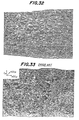
- Figs. 32 and 33 The roughness of LD material and SB material after painting are shown in Figs. 32 and 33 as a three-dimensional roughness chart, respectively, from which the LD material (Fig. 32) is considerably smooth in the painted surface as compared with the SB material (Fig. 33).
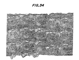
- Fig. 34 The three-dimensional surface roughness profile of the LD material before painting is shown in Fig. 34, from which the surface roughness profile is regularly formed in the LD material.
- the DOI value as a distinctness of image after painting is not less than 94.
- RA is not more than 2.0 pm
- the DOI value of not less than 94 is obtained in the sample A of LD material.
- the DOI value is not less than 98.
- the DOI value of not less than 98 is obtained in the sample B of LD material as shown in Fig. 31.
- the painting steel sheets according to the invention remarkable effect capable of more improving the distinctness of image after painting is obtained without damaging the press formability.
- the steel sheets having an improved distinctness of image after painting can be produced in practice.
Landscapes
- Chemical & Material Sciences (AREA)
- Engineering & Computer Science (AREA)
- Mechanical Engineering (AREA)
- Materials Engineering (AREA)
- Crystallography & Structural Chemistry (AREA)
- Thermal Sciences (AREA)
- Physics & Mathematics (AREA)
- Metallurgy (AREA)
- Organic Chemistry (AREA)
- Reduction Rolling/Reduction Stand/Operation Of Reduction Machine (AREA)
- Metal Rolling (AREA)
- Laser Beam Processing (AREA)
- Application Of Or Painting With Fluid Materials (AREA)
Description
- This invention relates to steel sheets suitable for being painted such as cold rolled steel sheets, zinc hot dipped or electroplated steel sheets, which are subjected to a forming operation, such as press forming, before or after a painting process in the production of an outer panel for automobiles or a decorative outer plate for electric appliances, and to a method of producing the same.
- As a typical example of the production of a paintable steel sheet, the cold rolled thin steel sheet is usually subjected to degreasing, annealing and temper rolling in this order. In this case, the temper rolling is to improve the galling resistance in the press forming by conducting a light rolling through work rolls having a dulled surface to give a proper surface roughness to the steel sheet surface.
- As a process for dulling the surface of the work roll to be used in the temper rolling, there have hitherto been practised a shot blast process and a discharge working process. When the work roll for temper rolling is subjected to a dulling according to these processes, an irregular roughness profile is formed on the surface of the work roll, and consequently the steel sheet after temper rolling indicates a rough surface comprising a plurality of irregular mountain and valley portions as shown in Fig. 1 or 2. If such a surface roughened steel sheet is subjected to a press forming, a lubricating oil is present in the valley portions to reduce friction force between press mold and steel sheet and hence make the press operation easy, while metallic powder separated out by the friction force to the mold is trapped in the valley portions to prevent the galling.
- Lately, the finish feeling after painting on vehicle body in passenger cars and trucks is a very important quality control item because the height in synthetic quality of automobile can directly be appealed to the eye of the user as a good finish quality. Now, there are several evaluation items on the painted surface. Among them, it is particularly important that a glossiness lessening irregular reflection on the painted surface and an image clarity defining few image strain are excellent. In general, the combination of the glossiness and the image clarity is called as a distinctness of image.
- It is known that the distinctness of image on the painted surface is dependent upon the kind of paint and the painting process but is strongly influenced by the rough surface of the steel sheet as a substrate. That is, when the ratio of flat portion occupied in the steel sheet surface is small and the unevenness is high, the ratio of flat portion occupied in the painted surface becomes small and the unevenness becomes larger, and consequently the irregular reflection of light is caused to damage the glossiness and also the image strain is produced to deteriorate the image clarity, so that the distinctness of image is degraded.
- In general, the roughness of the steel sheet surface is frequently represented as a center-line average roughness Ra. Further, it is known that as the center-line average roughness Ra becomes larger, the amplitude between mountain portion and valley portion becomes large and hence the unevenness of the painted surface becomes large and consequently the distinctness of image is degraded.
- As a method for evaluating the distinctness of image, there have been developed various systems. Among them, a value measured by means of a Dorigon meter made by Hunter Associates Laboratory or a so-called DOI value is most usually used. The DOI value is expressed by DOI=100×{RsRo o)/Rs, wherein Rs is an intensity of a specular reflected light when a light entered at an incident angle of 30° is reflected at a specular reflective angle of 30° with respect to a sample S, and RO.3 is an intensity of a scattered light at a reflective angle of 30°±0.3°. The relation between the DOI value indicating the distinctness of image and the center-line average roughness Ra is shown in Figs. 4 and 5. Fig. 4 is a case that a two-layer coating of 55 µm in thickness is applied to a steel sheet temper rolled with a roll dulled through the conventional shot blast process, and Fig. 5 is a case that a three-layer coating of 85 µm in thickness is applied to the same steel sheet as mentioned above. It can be understood from Figs. 4 and 5 that as the center-line average roughness Ra becomes large, the DOI value becomes small to degrade the distinctness of image.
- When the steel sheet is subjected to a temper rolling with work rolls dulled through the conventional shot blast process or discharge working process, it exhibits a rough surface comprised of irregular mountain portions and valley portions as previously mentioned, wherein the flat portion is very little. When the painting is applied to the steel sheet having such irregular mountain and valley portions, since the coating is formed along the slopes of the mountain and valley portions, the ratio of flat portion occupied in the painted surface becomes small as shown, for example, in Fig. 33 being mentioned later and consequently the distinctness of image is degraded. In the conventional shot blast process or discharge working process, such a problem can not be avoided, so that it is very difficult to provide a sufficiently improved distinctness of image on the painted surface.
- It is an object of the invention to provide steel sheets having an improved distinctness of image by improving the surface roughness profile of the steel sheet to lessen the unevenness of the painted surface after painting and increase the ratio of flat portion occupied in the painted surface so as to obtain a high specular light reflectivity and a small image strain, and to provide a method of efficiently producing steel sheets having such an improved surface roughness profile. Thus, the invention provides steel sheets having a distinctness of image considerably better than that of conventional sheets without the necessity of changing the usually used paint and the painting process.
- Various studies have been made with respect to a laser processing process different from the conventional processes as a dulling process of work rolls for temper rolling from which it has been found that when the steel sheet is subjected to a temper rolling with a work roll dulled through laser processing, the top of the mountain portion constituting the surface roughness becomes flat and also flat portions are formed in the valley portions between the mountain portions. Such an increase of flat portions means that is advantageous to flatten the outermost coating layer in the painting. That is, it is considered that the irregular reflection of light is small as compared with the irregularly rough surface as in the conventional shot blast or discharge worked sheet and hence the distinctness of image is improved.
- In Cahiers d'lnformations Techniques de la Revue de Metallurgie, Vol. 80, No. 5, May 1983, pages 393-401, there is disclosed the use of laser pulses to produce a work roll having a regular surface roughness profile consisting of microcraters disposed in juxtaposition.
- In accordance with the present invention, there has been found a surface roughness profile of steel sheet capable of greatly improving the distinctness of image on the painted surface after painting.
- According to the invention, there is provided a method of producing a steel sheet suitable for being painted, which comprises subjecting the surface of a work roll for temper rolling to a dulling of its surface by means of a high density energy source so as to form craters having a mean diameter d, and then temper rolling a steel sheet with a pair of work rolls, at least one of which is the dulled work roll produced in the foregoing manner, at a draft (À) of not less than 0.3% to transfer the pattern of the dulled work roll on to the surface of the steel sheet, whereby there is obtained a steel sheet characterized in having a center-line average surface roughness Ra within the range of 0.3 to 3.0 pm and a microscopic shape constituting said surface roughness which is comprised of trapezoidal mountain portions having a flat top surface, groove-like valley portions formed so as to surround a whole or a part of the mountain portion and middle flat portions formed between the mountain portions outside of the valley portion so as to be higher than the bottom of the valley portion and lower than or equal to the top surface of the mountain portion and wherein the following relationships are satisfied:


- The paintable steel sheets of the invention can be produced by subjecting the surface of a work roll for temper rolling to a dulling of its surface pattern effected by means of a high density energy source, and then temper rolling a steel sheet with a pair of work rolls, at least one of which is the dulled work roll produced in the foregoing manner, at a draft (λ) of not less than 0.3% to transfer the pattern of the dulled work roll onto the surface of the steel sheet.
- As the high density energy source, it is preferred to use a laser but alternatively plasma or an electron beam may be used.
- As the steel sheet to be dulled in the temper rolling, cold rolled steel sheets are usually used, but surface-treated steel sheets, which are previously subjected to zinc hot dipping or electroplating, as well as hot rolled steel sheets may also be used.
- The invention will now be described, by way of example, with reference to the accompanying drawings, wherein:
- Fig. 1 is a view illustrating a three-dimensional profile of surface roughness in a work roll dulled through the conventional discharge working process;
- Fig. 2 is a view illustrating a three-dimensional profile of surface roughness in a work roll dulled through the conventional shot blast process;
- Fig. 3 is a schematic view showing the measurement of DOI value as a distinctness of image;
- Figs. 4 and 5 are graphs showing a relation between center-line average roughness Ra of steel sheet temper rolled with a work roll dulled through the shot blast process and DOI value after painting, wherein Fig. 4 shows results of two-layer coating and Fig. 5 shows results of three-layer coating;
- Fig. 6 is a diagrammatically section view partially showing the dulled state of work roll through laser pulse as a high density energy source according to the invention;
- Fig. 7 is a schematically sectional view showing a surface roughness profile of the work roll dulled through the laser pulse;
- Fig. 8 is a plan view of Fig. 7;
- Fig. 9 is a diagrammatically section view showing a state of subjecting the steel sheet to a temper rolling with the work roll shown in Figs. 6-8;
- Fig. 10 is a schematically sectional view showing a surface roughness profile of the steel sheet after the temper rolling of Fig. 9;
- Fig. 11 is a plan view of Fig. 10;
- Fig. 12a is a graph showing a distribution of mountain height in the surface of the work roll dulled through the conventional shot blast process;
- Fig. 12b is a graph showing a distribution of mountain height in the surface of the work roll dulled through the conventional discharge working process;
- Fig. 13 is a schematic view illustrating a state that the steel sheet is dulled by temper rolling with the work roll dulled through the conventional process;
- Fig. 14a is a graph showing an inclination angle distribution in the surface roughness of the steel sheet temper rolled with the work roll dulled through the conventional shot blast process;
- Fig. 14b is a graph showing an inclination angle distribution in the surface roughness of the steel sheet temper rolled with the work roll dulled through the laser process;
- Fig. 14c is a graph showing an inclination angle distribution of the steel sheet temper rolled with so-called bright work roll not dulled after polishing;
- Fig. 15 is a schematic view showing the definition of inclination angle in Fig. 14a;
- Fig. 16 is a schematic view illustrating the definitions in dimension of each part of profiles constituting rough surfaces of the work roll for temper rolling and the dulled steel sheet;
- Fig. 17 is a model view showing the definition in area ratio of flat portion η(=η1+η2);
- Fig. 18 is a schematic view for approximate calculation of surface roughness profile in the work roll and steel sheet;
- Fig. 19 is a graph showing a relation between a draft in the temper rolling and a transfer ratio of roughness h2/1;
- Fig. 20 is a graph showing a relation between the area ratio of flat portion η at the steel sheet surface and the draft A in the temper rolling in accordance with the value of Sm/D;
- Fig. 21 is a graph showing a relation between the area ratio of flat portion η of the steel sheet and a DOI value after painting in case of three-layer coating;
- Figs. 22a to 22c are schematic views showing a change of roughness profile in the flat surface of the steel sheet when varying Sm/D;
- Fig. 23 is a diagrammatically section view of a microscopic profile at the surfaces of work roll and steel sheet when the ratio of Sm/D is excessive;
- Fig. 24 is a schematic view when the steel sheet of Fig. 23 is subjected to a press forming;
- Fig. 25 is a graph showing the galling limit in the press forming test varying (Sm-D)2;
- Fig. 26 is a graph showing the galling limit in the similar test varying Sm/D;
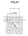
- Fig. 27 is a schematic view showing a width of middle flat portion (Sm-D);
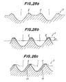
- Figs. 28a to 28c are schematic views illustrating the state of work roll through laser processing when the ratio of Sm/D is varied around 0.85;
- Fig. 29 is a graph showing a relation between the ratio of Sm/D and a diameter of a top surface in mountain portion of the steel sheet surface as a proper region;
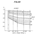
- Fig. 30 is a graph showing proper regions of À, n and Sm/D;
- Fig. 31 is a graph showing a relation between the center-line average roughness Ra of the steel sheet and the DOI value after painting in case of three-layer coating;
- Fig. 32 is a chart showing a three-dimensional roughness of a coating formed on the steel sheet temper rolled with a work roll dulled through laser process;
- Fig. 33 is a chart showing a three-dimensional roughness of a coating formed on the steel sheet temper rolled with a work roll dulled through the conventional shot blast process; and
- Fig. 34 is a view illustrating a three-dimensional profile of surface roughness in the steel sheet temper rolled with a work roll dulled through laser process.
- The invention will be described in detail below.
- A work roll for temper rolling is dulled through a high density energy source, e.g. a laser as follows.
- A laser pulse is projected onto the surface of the rotating work roll in sequence to regularly fuse surface portions of the roll exposed to a laser energy, whereby crater-like concave portions are regularly formed on the roll surface. Fig. 6 sectionally shows a part of the dulled roll surface, wherein numeral 1 is a crater-like concave portion (hereinafter referred to as a crater simply) formed on a surface of a
work roll 3. The fused base metal of the roll upheaves upward from thesurface level 6 of theroll 3 in the form of ring around thecrater 1 to form a flange-like upheaved portion 2 (hereinafter referred to as a flange simply). Moreover, the inner wall layer of thecrater 1 inclusive of theflange 2 is a heat-affected zone to abase metal structure 4 of the roll. - Then, the dulling through laser as described above will be explained in detail.
- The depth and diameter of the
crater 1 formed on the roll surface through laser pulse are determined by the intensity of energy in the incident laser and the projecting time, which gives a quantity defining a roughness corresponding to surface roughness Ra in the work roll dulled through the conventional shot blast process. - The base metal of the roll heated by laser instantly changes into a metallic vapor due to large energy density of irradiated laser. In this case, the fused metal is blown away from the roll surface by the generated vapor pressure to form the
crater 1, while the blown fused metal again adheres to the circumference of thecrater 1 to form theflange 2 surrounding thecrater 1. Such a series of actions are more efficiently performed by blowing an auxiliary gas such as oxygen gas or the like to the reaction point. - The
above craters 1 are regularly formed by regularly irradiating the laser pulse while rotating or axially moving the work roll, whereby the surface of the roll is rendered into a rough state through the gathering of these formed craters. The rough state of the roll surface is shown in Figs. 7 and 8. As seen from Figs. 7 and 8, a portion located between theadjacent craters 1 outside theflange 2 is aflat surface 6 corresponding to the original roll surface. Moreover, the mutual distance between the adjacent craters can be adjusted by controlling the frequency of laser pulse in relation to the rotating speed of the roll in the rotating direction of the roll and by controlling the pitch of moving the irradiation position of the laser in the axial direction of the roll. - Although the invention has been described with respect to the use of laser as a high density energy source, similar results are obtained when using a plasma or an electron beam as a high density energy source.
- A steel sheet such as a cold rolled steel sheet after annealing or the like is rolled at a light draft at the temper rolling step using the work roll dulled through laser as mentioned above, whereby the dull pattern formed on the surface of the work roll is transferred to the surface of the work roll is transferred to the surface of the steel sheet to thereby give a rough surface to the steel sheet.
- When microscopically observing the steel sheet surface at the temper rolling step, as shown in Fig. 9, the
flanges 2 having substantially a uniform height around thecrater 1 on the surface of theroll 3 is pushed to the surface of thesteel sheet 7 under a strong pressure, whereby the local plastic flow of material is caused near the surface of thesteel sheet 7 softer than the material of theroll 3 and consequently metal of thesteel sheet 7 flows into thecraters 1 of theroll 3 to render the steel sheet surface into a rough state. In this case, atop surface 8 of the upheaved steel sheet inside thecrater 1 becomes flat likewise the original steel sheet surface, while thatportion 9 of the steel sheet which is pushed by theflat portion 6 between theadjacent craters 1 outside theflange 2 in theroll 3 is flat as it is, and the formerflat surface 8 is higher than or equal to the latterflat surface 9. Therefore, as shown in Figs. 10 and 11, the microscopic shape of surface roughness in thesteel sheet 7 after the temper rolling is comprised oftrapezoidal mountain portions 10 having a flattop surface 8, groove-like valley portions 11 formed so as to surround the mountain portions, and middleflat portions 9 formed between the adjoiningmountain portions 10 outside thevalley portion 11 so as to be higher than the bottom of thevalley portion 11 and lower than or equal to the top surface of themountain portion 10. - As seen from the above, the ratio of flat portions comprising the
top surface 8 of themountain portion 10 and the middleflat portion 9 becomes larger in the surface of steel sheet after the temper rolling, while the ratio ofslope 13 between themountain portion 10 and thevalley portion 11 becomes principally small. - On the other hand, in case of the work roll dulled through the shot blast process or the discharge working process, the roughness of the roll surface has various mountain heights similar to normal distribution as shown in Fig. 12a or 12b. In this case, the surface roughness profile of the
roll 3 is synthesized with the surface roughness profile of theoriginal steel sheet 7 by the encroach of mountains in theroll 3 on the surface of thesteel sheet 7 as shown in Fig. 13, so that the ratio of slopes between the mountain and the valley becomes principally larger in thesteel sheet 7 after the temper rolling. Therefor, the structure and formation step of surface roughness profile by the conventional technique are entirely different from those in the steel sheet temper rolled with the work roll dulled through the laser process. - In Fig. 14a is shown an inclination angle distribution of surface roughness in the steel sheet after the temper rolling using the work dulled through the conventional shot blast process. The definition of the inclination angle (6) is illustrated in Fig. 15. Since the DOI value indicating the distinctness of image is represented by a ratio of the scattered light at a reflective angle of 30°±0.3° to the specular reflected light as previously mentioned, the flatness can be judged to be good when the ratio of valley portion having θ as an inclination angle with tolerance of ±0.3° is large. In case of Fig. 14a, however, the occupation ratio (W2o) of tan θ≤ ±0.3° is only 14%. On the othe rhand, when the steel sheet is temper rolled with the work roll dulled through the laser process, the occupation ratio is 26%, which becomes closer to the occupation ratio of 36% in the bright steel sheet when comparing Fig. 14b with Fig. 14c. Thus, the high flatness can be obtained in the invention.
- The dimension in each part of surface roughness profile of the work roll dulled through the aforementioned laser process and the steel sheet temper rolled therewith is defined with reference to Fig. 16 as follows:
- D: mean outer diameter of
flange 2 on roll surface or mean diameter of outer periphery ofvalley portion 11 on steel sheet surface; - d: mean diameter of
crater 1 on roll surface; - do: mean diameter of flat
top surface 8 ofmountain portion 10 on steel sheet surface; - H: depth of
crater 1 on roll surface; - h1: height of
flange 2 on roll surface or depth ranging from middleflat portion 9 to bottom ofvalley portion 11 on steel sheet surface; - h2: height ranging from flat
top surface 8 to middleflat portion 9 inmountain portion 10 on steel sheet surface; - Sm: mean center distance between adjoining
craters 1 on roll surface or between adjoiningmountain portions 10 on steel sheet surface; - a: width of
flange 2 on roll surface. - The influences of the pattern constituting the surface roughness profile of the roll and the temper rolling conditions upon the area ratio η of flat surface portions of the steel sheet after the temper rolling are examined by using the values as previously defined.
- The area ratio η of flat portions is represented by a sum of area occupation ratio η1 of flat
top surface 8 ofmountain portion 10 and area occupation ratio η2 of middleflat portion 9, i.e.
- Moreover, the value of η1 varies in accordance with the draft in the temper rolling, because the degree of flowing metal of steel sheet into the
crater 1 changes with the change of the draft and hence the diameter do oftop surface 8 ofmountain portion 10 changes. On the other hand, the value of η2 is constant in accordance with the value of Sm/D. - The ratio of Sm/D is within a range defined by the following equation (2) as mentioned later:

- Moreover, η1 is determined by the following equation (3), and do is constantly related to d as shown in the following equation (4), and η2 is determined in accordance with the value of Sm/D by the following equation (5):


- In the equation (5), when Sm/D≥1, a=O, while when Sm/D<1, a=1. When these data are applied to the equations (2) and (5), η2 is within a range defined in the following equation (6):

- As to the sectional shape of surface roughness profile in each of the roll surface and steel sheet surface, when x axis and y axis are taken as shown in Fig. 18, assuming that the sectional shape of
crater 1 is y=cos x, the following equations (7) and (8) are established at d=n and cos do/2=h2.

- Now, a ratio of height h2 of
mountain portion 10 transferred onto the steel sheet surface through the crater. to depth H of thecrater 1 can be called as a roughness transfer ratio. In the aforementioned embodiment, the depth H ofcrater 1 is 1, so that the roughness transfer ratio is h2/1 or h2. - Such a roughness transfer ratio h2/1 or the height h2 of
mountain portion 10 is related to the draft λ in the temper rolling as shown in the following equation:
- An SPCC steel sheet having a roughness Ra of 0.38 pm and a thickness of 0.32 mm was temper rolled at various drafts A by using a work roll having a diameter of 200 mm and an Hs hardness of 94, which was dulled to Ra of 3.54 pm through the laser process, as a roll for temper rolling. The results are shown in Fig. 19.
- As seen from Fig. 19, the roughness transfer ratio h2/l linearly increases when the draft \ rises up to about 1.5% and is saturated when the draft λ exceeds 1.8%.
- The values of do, k and k2 are measured from the results of Fig. 19 to obtain results as shown in the following Table 1.

- When the dulling through laser is performed so as to provide the same average roughness Ra of 1.0-3.0 µm as in the cold rolled steel sheet for usual press forming, the width a of flange between craters is about 0.09xD. Therefore, d is expressed by the following equation (10):

- When the equation (10) is applied to the equation (4),


- From the equations (5), (6) and (12) and results of Table 1, the area ratio n of flat portions is shown in the following Table 2, in which the first two sets of figures are comparative examples. Such an area ratio η is shown in Figure 20 in accordance with the value of Sm/D. Further, this relation can be generalized by the following equation (13):

- It is obvious from Fig. 20 that the area ratio of flat portions largely changes in accordance with the ratio of Sm/D. And also, η changes in accordance with the draft λ in temper rolling. Particularly, η is largely influenced by the change of λ when Sm/D is small.


- As mentioned above, the draft λ in temper rolling influences on η, but when A is too small, the temper rolling operation itself is unstable and it is difficult to conduct the dulling of the steel sheet surface. The inventor has found that the dulling is possible when the draft in temper rolling is not less than 0.3%. Therefore, the lower limit of the draft η is 0.3%.
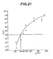
- In the dulling of the work roll for temper rolling through the laser, Sm, D and d as well as the draft η were varied to obtain steel sheets having various area ratio η of flat portions (Ra: approximately 1.5 um). After a black paint was applied to the steel sheet as a three-layer coating, the DOI value on the painted surface was measured to obtain results as shown in Fig. 21.
- As seen from Fig. 21, the DOI value increases as η becomes large, and hence the distinctness of image becomes good. In general, it is desirable that DOI value is not less than 94% for giving satisfactory high-grade feeling to the coating on the vehicle body. For this purpose, it is desired that η is not less than 35%. When the high-grade feeling is not so required, however, η is sufficient to be not less than 20%. Therefore, the lower limit of η is 20%.
- The dimensions such as D, Sm, H and the like in the surface roughness profile of the roll defined in the above item [3] can be changed by adjusting the dulling conditions of work roll for temper rolling through laser such as revolution number of roll, frequency of laser pulse, output of laser, speed of feeding laser irradiation point and laser irradiation time, or the blowing condition of auxiliary gas such as 02 gas or the like as seen from the above. If it is intended to temper roll the usual formable cold rolled steel sheet with the work roll dulled to Ra of 0.5-5 gm through the laser, the surface of the work roll has a flange width a of about 20-40 pm and a flange height h, of about 5-30 pm.
- In the surface roughness profile formed on the steel sheet, three patterns as shown in Figs. 22a to 22c are obtained in accordance with the value of Sm/D. That is, when Sm/D is 1, the adjoining
valley portions 11 just come into contact with each other as shown in Fig. 22a. When Sm/D>1, the adjoiningvalley portions 11 separate away from each other as shown in Fig. 22b. Further, when Sm/D<1, the adjoiningvalley portions 11 overlap with each other as shown in Fig. 22c. - Thus, various patterns of the surface roughness profile can be obtained by changing the value of Sm/D. In this connection, work rolls for temper rolling having various values of Sm/D were prepared through the laser process, and then the formation of dull pattern on the cold rolled steel sheet after annealing was performed by temper rolling at a proper draft with these work rolls. Thereafter, the dulled steel sheet was subjected to a press forming test and a painting test, from which the following knowledges were obtained.
- Namely, when the
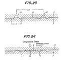
steel sheet 7 is temper rolled with thework roll 3 as shown in Fig. 23, as the value of Sm/D in the roll becomes considerably large, the area of the middleflat portion 9 existent between the adjoiningmountain portions 10 on the steel sheet surface is excessive. As a result, when such a steel sheet is subjected to a press forming as shown in Fig. 24,metallic debris 13 exfoliated at the wider middleflat portion 9 during the press forming are difficult to be trapped by thevalley portion 11 and remain betweenpress tool 14 and middleflat portion 9. Furthermore, the feature that Sm/D is considerably large means that the space of thevalley portion 11 acting to reserve a lubricating oil becomes relatively small and is apt to cause poor lubrication. Therefore, when Sm/D is too large, the galling is liable to be caused in the press forming. - Moreover, it is required to control the width of middle
flat portion 9 or absolute value of Sm-D from the following reason. - The size of the flange formed on the roll surface through the laser process, i.e. width a and height h, are related to a course that a part of metal in the crater portion fused by laser upheaves at its circumference and is resolidified. When D is large, a and h, also become large. That is, when D is large, a capacity of reserving a lubricating oil in the press forming and a capacity of trapping exfoliated metallic debris become large, which is significant for preventing the galling. However, the effectiveness is restricted to such a case that concave portion such as groove or the like capable of trapping exfoliated metallic debris is existent on the surface of the material to be worked in such a relative sliding length between the press mold and the material that the exfoliated metallic debris gradually deposit and finally cause the galling. In order to satisfy this requirement, it is necessary that the absolute value of width of middle flat portion (Sm-D) is made smaller than a certain value.
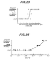
- It has been found from the aforementioned experiments that in case of steel sheets not having a very high formability, which are used as an outer panel for automobile requiring particularly a high distinctness of image, since the strain ratio in the press forming is within 10%, unless the value of Sm/D exceeds 3.0, the galling is not frequently caused in the press forming as shown in Fig. 26 (○, Δ and x).
- As previously mentioned, the flanges are formed on the roll surface around the craters by blowing the auxiliary gas to upheave metal fused by laser onto the roll surface. In this case, the flange does not necessarily take a circle due to slight ununiformity of auxiliary gas flowing distribution and fluctuation of flowing rate, i.e. a part of the flange is cut off. Therefore, in the surface of the steel sheet temper rolled by the work roll having the above flanges of irregular form, a part of the mountain portion is not surrounded by the valley portion, which results in the increase of η to improve the distinctness of image. The same experiment as described above was made with respect to such a steel sheet to obtain results (•, A and #) as shown in Fig. 26, therb is no great difference in the press formability between the case that the mountain portion is completely surrounded by the valley portion and the case that the mountain portion is partially surrounded by the valley portion.
- Further, it has been found that the absolute value of width of middle flat portion 9 (Sm-D) is required to be made smaller than 450 µm in order to prevent the frequency occurrence of galling as shown in Fig. 25. The results of these experiments are shown in the following Table 3, wherein the definitions of (Sm-D), and (Sm-D)2 are shown in Fig. 27, respectively. Samples Nos. A3, A4, B2, B3, B4, C3 and C4 are comparative examples.

- As previously mentioned on Fig. 20, the value of Sm/D is interrelated to the area ratio η of flat portions on the steel sheet surface. According to the above experiments, the galling frequently occurs when the area ratio η exceeds 95% as can be seen from Table 3.
- According to the invention, therefore, the upper limit of Sm/D is 3.0, the upper limit of area ratio η is 95%, and the upper limit of (Sm-D) is less than 450 pm in order to provide steel sheets causing no galling and having a good press formability.
- When the ratio of Sm/D is less than 0.85, the dulling operation of work roll through the high density energy source such as laser or the like is unstable and the control of Ra is difficult. Further, the change of surface roughness in the work roll is conspicuous in the temper rolling operation and the ragging is apt to be caused by exfoliating a part of the roll constituting the rough surface. This is due to the following reason.
- In general, the flange width a is formed within a range of α=0.1―0.3 D with respect to the outer diameter D of the flange so as to attain the reserving of the lubricating oil and the trapping of metallic debris exfoliated in the press working. When Sm/D exceeds 1, the adjoining
flanges 2 separate away from each other as shown in Fig. 28a, while when Sm/D is less than 1, the adjoiningflanges 2 overlap with each other. Moreover, when a=0.3 D and Sm=0.85 D, molten metal generated from the adjoining crater rides on the previously formedflange 2 as shown in Fig. 28b, so that the height h, of the resultingflange 2 is about two times that of the case having no piling of molten metal. - Further, when Sm>0.85 D (a=0.3 D), molten metal flows into the previously formed crater from the adjoining crater as shown in Fig. 28c, whereby the depth H of the
crater 1 and the height h, and width a of the flange are changed. Thus, when molten metal flows onto the previously solidified metal in the crater, aclear boundary 15 is formed between the previously solidified metal layer and the later solidified metal layer, at where both the layers are apt to be separated by external force, which is liable to cause the ragging in the temper rolling. - From the above facts, the lower limit of Sm/D should be 0.85.
- The flat
top surface 8 ofmountain portion 10 constituting the microscopic surface roughness profile of steel sheet is a plane bearing the press load in the press forming, which corresponds to a so-called load bearing area. - As the diameter do of the
top surface 8 becomes large, the area of this flat top surface becomes large, which tends to cause the galling likewise the case that Sm/D and η are large as previously mentioned on the item [7]. The inventor has found from the experiments that when do exceeds 500 pm, the galling is apt to be caused. Further, in order to form a widetop surface 8 having do of more than 500 pm, it is necessary that the diameter of thecrater 1 in the roll is also made large. For this purpose, the energy quantity required in the laser pulse irradiation for the formation of craters should be excessive, which requires the use of a laser generator having a considerably large output or the prolonging of irradiation time by decreasing the revolution number of the roll. This is not only disadvantageous in economy but also brings about the decrease of total treating efficiency and reliability. Therefore, the upper limit of do should be 500 pm. - On the other hand, when the diameter do of the
top surface 8 inmountain portion 10 is too small, themountain portion 10 is apt to be broken by compressive stress and shearing stress in the press forming to produce a large amount of metallic debris therefrom, which is also liable to cause the galling. The inventor has confirmed that the galling is apt to be caused when do is less than 30 pm. As do becomes small, the value of D is necessarily small, so that the value of Sm itself should be small in order to satisfy Sm/D≤3.0 as previously mentioned on the item [7] when do is made small. That is, the distance between the craters in the roll should be small. For this purpose, the revolution number of roll is extremely decreased in the laser irradiation or the frequency of laser pulse is considerably increased, which becomes disadvantageous in economy. From these reasons, the diameter do of thetop surface 8 inmountain portion 10 should be not less than 30 µm. - In the invention, the diameter do of the
top surface 8 is sufficient within a range of 30-500 µm on average. In fact, when themountain portions 10 are formed by temper rolling with the work roll dulled through the high density energy source such as laser, the plan form of the flattop surface 8 in themountain portion 10 is not always true circle and frequently becomes oblong or irregular. In the latter case, therefore, it is desirably adjusted that the mean value of major axis in top surfaces is not more than 500 pm and the mean value of minor axis in top surfaces is not less than 30 µm. Of course, it is most suitable that the maximum major axis in all top surfaces is not more than 500 pm and the minimum minor axis in all top surfaces is not less than 30 pm. - According to the invention, it is most important to control the microscopic profile forming the rough surface of steel sheet as previously mentioned, and also it is important to control the surface roughness of steel sheet.
- Even when the microscopic profile is controlled as mentioned above, if the center-line average roughness Ra exceeds 3.0 pm, the distinctness of image after painting is not sufficiently good, while if Ra is less than 0.3 pm, the galling is apt to be caused in the press forming. Therefore, Ra should be within a range of 0.3-3.0 pm. Preferably, Ra is not more than 3.0 µm in order to provide a DOI value of not less than 94 as a distinctness of image.
- As mentioned above, in order that the steel sheets temper rolled with the work roll dulled through the high density energy source such as laser or the like have a good press formability (or resistance to galling) and an excellent distinctness of image for painting required in automobiles, preferably DOI value of not less than 94, it is necessary that the microscopic surface roughness profile of steel sheet satisfies the following conditions:
- (i) a ratio of a sum of areas of flat portions (top surface of mountain portion and middle flat portion) to whole area (area occupation ratio of flat portions, η) is not less than 20% (preferably not less than 35%) but not more than 95%;
- (ii) a ratio (Sm/D) of mean center distance Sm between mountain portions to mean diameter D of outer periphery of valley portion is within a range of 0.85-3.0 and Sm-D is less than 450 µm; and
- (iii) a mean diameter do of top surface of mountain portion is within a range of 30-500 µm. Besides, the center-line average roughness Ra is necessary to be within a range of 0.3-3.0 µm. Moreover, the draft A in temper rolling is required to be not less than 0.3%.
- Among the above conditions, a relation between Sm/D and do is shown in Fig. 29 together with its reasonable range and limitation reason. Further, the adaptable range of Sm/D for putting η into an optimum range (20-95%) when varying the draft λ in temper rolling is shown in Fig. 30.
- The following example is given in illustration of the invention and is not intended as limitations thereof.
- As a starting sheet was used a cold rolled steel sheet of 0.8 mm in thickness, which was produced by cold rolling a steel sheet containing C: 0.04%, Mn: 0.2%, P: 0.02%, S: 0.015%, N: 0.003% and 0: 0.005% at a draft of 69.2% and annealing in a box annealing furnace.
- As a work roll for temper rolling, there were provided a roll dulled through a laser pulse process, a roll dulled through the conventional shot blast process, a roll dulled through the conventional discharge working process, and a bright roll not diluted. Then, the cold rolled steel sheet was temper rolled with this work roll at a draft A ranging from 0.5% to 2.5%.
- The surface roughness Ra of the bright roll was 0.15 pm, while the surface roughness Ra of the dulled roll was within a range of 1.1-5.6 µm. As the surface roughness profile of the work roll dulled through the laser pulse process, there were particularly provided sample A with 0.85≤Sm/D≤1.7, Sm-D<280 µm, 50 µm≤d≤500 µm, 35 µm≤H≤120 µm and h1≃1/3H, and a sample B with 1.7≤Sm/D≤3.0, Sm-D<450 µm, 50 µm≤d≤500 µm, 35 µm≤H≤120 µm and h1≃1/3H.
- The surface roughness of the temper rolled steel sheet was Ra=0.08 pm in case of using the bright roll and Ra=0.6-2.25 pm in case of using the dulled roll. Particularly, in the steel sheet temper rolled with the work roll dulled through the laser pulse process, the surface roughness profile on sample A had 0.85≤Sm/ D≤1.7, Sm-D<280 µm and 30 µm≤d≤500 µm, and that on sample B had 1.7≤Sm/D≤3.0, Sm-D<450 µm and 30 µm<d≤500 pm.
- Then, the temper rolled steel sheet was subjected to a phosphating treatment under the following conditions:
- Treating material: granulated phosphate agent for dipping treatment.
- Dipping conditions: 43°Cx 120 seconds.
- Weight of phosphate layer: 2.3±2 g/cm2.
- Pretreatment: degreasing, washing with water, surface adjustment.
- Post treatment: washing with water, washing with pure water, drying.
- After the phosphating treatment, three-layer coating was formed under the following conditions:
- Painting posture: horizontal.
- Undercoat: Cation ED paint, 18-20 pm thickness.
- Inter coat: sealer, 30-35 µm thickness.
- Top coat: 30-35 pm thickness.
- Moreover, the sanding was not performed in each painting step.
- After the painting, DOI value of the painted surface was measured by means of a Dorigon meter.
- The measured results are shown in Fig. 31 in connection with the surface roughness Ra of the steel sheet, wherein LD material is a steel sheet temper rolled with the work roll dulled through the laser pulse process, EDT material is a steel sheet temper rolled with the work roll dulled through the distance working process, SB material is a steel sheet temper rolled with the work roll dulled through the shot blast process, and bright roll material is a steel sheet temper rolled with the so-called bright roll not dulled.
- As seen from Fig. 31, the sample A of LD material is excellent by about 10-11 points in the DOI value as a distinctness of image as compared with EDT and SB materials, and the sample B of LD material is further excellent by 1 point in the DOI value and has a DOI value of 98.
- The roughness of LD material and SB material after painting are shown in Figs. 32 and 33 as a three-dimensional roughness chart, respectively, from which the LD material (Fig. 32) is considerably smooth in the painted surface as compared with the SB material (Fig. 33).
- The three-dimensional surface roughness profile of the LD material before painting is shown in Fig. 34, from which the surface roughness profile is regularly formed in the LD material.
- As previously mentioned, it is desirable that the DOI value as a distinctness of image after painting is not less than 94. In the above example, it is apparent from Fig. 31 that when RA is not more than 2.0 pm, the DOI value of not less than 94 is obtained in the sample A of LD material. Further, since the highest painting quality is required in high-grade cars, it is desired that the DOI value is not less than 98. In this connection, the DOI value of not less than 98 is obtained in the sample B of LD material as shown in Fig. 31.
- Moreover, it has been confirmed from the press forming test of outer panel for automobile that the galling is not caused in the press forming of the sample B of LD material, and when Ra is less than 0.3 pm, the galling frequently occurs in the press forming.
- In the painting steel sheets according to the invention, remarkable effect capable of more improving the distinctness of image after painting is obtained without damaging the press formability. According to the method of the invention, the steel sheets having an improved distinctness of image after painting can be produced in practice.
Claims (2)
Applications Claiming Priority (4)
| Application Number | Priority Date | Filing Date | Title |
|---|---|---|---|
| JP61007769A JPS62168602A (en) | 1986-01-17 | 1986-01-17 | Steel sheet for painting and its production |
| JP7769/86 | 1986-01-17 | ||
| JP278876/86 | 1986-11-25 | ||
| JP61278876A JPS63132702A (en) | 1986-11-25 | 1986-11-25 | Steel sheet for painting and its production |
Publications (2)
| Publication Number | Publication Date |
|---|---|
| EP0234698A1 EP0234698A1 (en) | 1987-09-02 |
| EP0234698B1 true EP0234698B1 (en) | 1990-12-12 |
Family
ID=26342124
Family Applications (1)
| Application Number | Title | Priority Date | Filing Date |
|---|---|---|---|
| EP87300321A Expired - Lifetime EP0234698B1 (en) | 1986-01-17 | 1987-01-15 | Steel sheets for painting and a method of producing the same |
Country Status (7)
| Country | Link |
|---|---|
| US (1) | US4798772A (en) |
| EP (1) | EP0234698B1 (en) |
| KR (1) | KR900006496B1 (en) |
| CN (1) | CN1010752B (en) |
| BR (1) | BR8700220A (en) |
| CA (1) | CA1305298C (en) |
| DE (1) | DE3766627D1 (en) |
Cited By (4)
| Publication number | Priority date | Publication date | Assignee | Title |
|---|---|---|---|---|
| WO2018149966A1 (en) | 2017-02-17 | 2018-08-23 | Voestalpine Stahl Gmbh | Method for producing steel sheets, steel sheet, and use thereof |
| WO2018149961A1 (en) | 2017-02-17 | 2018-08-23 | Voestalpine Stahl Gmbh | Method for producing steel sheets, steel sheet and use thereof |
| WO2018149967A1 (en) | 2017-02-17 | 2018-08-23 | Voestalpine Stahl Gmbh | Method for producing steel sheets, steel sheet and use thereof |
| US10683560B2 (en) | 2014-10-09 | 2020-06-16 | Thyssenkrupp Steel Europe Ag | Cold-rolled and recrystallization annealed flat steel product, and method for the production thereof |
Families Citing this family (27)
| Publication number | Priority date | Publication date | Assignee | Title |
|---|---|---|---|---|
| JPS62230402A (en) * | 1986-03-31 | 1987-10-09 | Kawasaki Steel Corp | Steel sheet to be painted and its production |
| US5182171A (en) * | 1986-06-26 | 1993-01-26 | Taiyo Steel Co., Ltd. | Conductive and corrosion-resistant steel sheet |
| JPS6311689A (en) * | 1986-06-30 | 1988-01-19 | Kawasaki Steel Corp | Steel sheet for di can |
| LU86531A1 (en) * | 1986-07-28 | 1988-02-02 | Centre Rech Metallurgique | METAL PRODUCT HAVING IMPROVED SHINE AFTER PAINTING AND METHODS OF MAKING SAME |
| US4861441A (en) * | 1986-08-18 | 1989-08-29 | Nippon Steel Corporation | Method of making a black surface treated steel sheet |
| US4978583A (en) * | 1986-12-25 | 1990-12-18 | Kawasaki Steel Corporation | Patterned metal plate and production thereof |
| US5114514A (en) * | 1990-05-30 | 1992-05-19 | Eastman Kodak Company | Bonding of thermoplastic sheet material to roughened substrates |
| CA2095228C (en) * | 1991-09-03 | 1997-01-14 | Takaharu Kawamoto | Steel strip having excellent painting sharpness and press moldability and method for producing rolling dull roll |
| JP2704070B2 (en) * | 1991-10-30 | 1998-01-26 | 川崎製鉄株式会社 | Alloyed hot-dip galvanized steel sheet with excellent press mold sliding properties |
| US5250364A (en) * | 1992-02-03 | 1993-10-05 | Aluminum Company Of America | Rolled product with textured surface for improved lubrication, formability and brightness |
| US5591534A (en) * | 1994-03-25 | 1997-01-07 | Sorevco, Inc. | Enhanced protective metallic coating weights for steel sheet |
| SE502819C2 (en) * | 1994-07-19 | 1996-01-22 | Volvo Penta Ab | Surface-treated corrosion-protected metal article and method of corrosion-resistant treatment of the article |
| BE1010589A3 (en) * | 1996-08-29 | 1998-11-03 | Ebt Gmbh | Method for manufacturing a surface structure and tools equipped with such a surface structure |
| DE10006348C2 (en) * | 2000-02-12 | 2001-12-06 | Daimler Chrysler Ag | Component with locally limited stiffening areas and method for its production |
| JP4473715B2 (en) * | 2004-11-29 | 2010-06-02 | 富士通株式会社 | LAMINATE CUTTING METHOD AND LAMINATE |
| US20070141266A1 (en) * | 2005-12-21 | 2007-06-21 | Greenlee Greg T | Construction hardware and method of reducing corrosion thereof |
| WO2008108044A1 (en) * | 2007-03-01 | 2008-09-12 | Jfe Steel Corporation | High tensile cold rolled steel plate and method for manufacturing the cold rolled steel plate |
| DE502007004723D1 (en) * | 2007-06-22 | 2010-09-23 | Laser Walzen Ct Gmbh | Flat product of a metal material, in particular a steel material, use of such a flat product and roller and method for producing such flat products |
| MX2018004512A (en) * | 2015-10-14 | 2018-08-01 | Novelis Inc | Engineered work roll texturing. |
| DE102016102723B3 (en) | 2016-02-16 | 2017-06-01 | Salzgitter Flachstahl Gmbh | Tempering roller, method for applying a flat product hereby and flat product thereof |
| CN108453028B (en) * | 2018-03-26 | 2021-05-04 | 重庆搏成防腐工程有限公司 | In-service oil tank inner surface anticorrosion construction process based on laser technology |
| DE102019214136A1 (en) * | 2019-09-17 | 2021-03-18 | Thyssenkrupp Steel Europe Ag | Sheet steel with a deterministic surface structure |
| DE102019214135A1 (en) * | 2019-09-17 | 2021-03-18 | Thyssenkrupp Steel Europe Ag | Sheet steel with a deterministic surface structure |
| DE102019216338A1 (en) * | 2019-10-23 | 2021-04-29 | Thyssenkrupp Steel Europe Ag | Process for surface treatment of a sheet metal and surface-treated sheet metal |
| DE102019219651A1 (en) * | 2019-12-16 | 2021-06-17 | Thyssenkrupp Steel Europe Ag | Sheet metal with a deterministic surface structure and process for the production of a formed and painted sheet metal component |
| CN111266404B (en) * | 2020-02-21 | 2021-05-18 | 贵研铂业股份有限公司 | Preparation method of titanium substrate for coated titanium anode plate |
| CN111438186B (en) * | 2020-03-31 | 2022-01-18 | 首钢京唐钢铁联合有限责任公司 | Preparation method of five-tandem mill strip steel |
Family Cites Families (12)
| Publication number | Priority date | Publication date | Assignee | Title |
|---|---|---|---|---|
| US2991544A (en) * | 1957-05-07 | 1961-07-11 | American Can Co | Bright surfaced metal sheets and method of producing same |
| DE1247251B (en) * | 1964-04-25 | 1967-08-17 | Opel Adam Ag | Draw sheet for drawn parts |
| US3619881A (en) * | 1969-01-17 | 1971-11-16 | United States Steel Corp | Cold rolling work roll |
| US3623850A (en) * | 1969-03-24 | 1971-11-30 | Bethlehem Steel Corp | Composite chill cast iron rolling mill rolls having increased resistance to the spalling |
| US4111032A (en) * | 1974-11-06 | 1978-09-05 | Societe Lorraine De Laminage Continu | Process for producing a metal sheet to be deep drawn or extra-deep drawn for the fabrication of shaped metal parts |
| FR2290623A1 (en) * | 1974-11-06 | 1976-06-04 | Lorraine Laminage | SHEET FOR DEEP OR EXTRA-DEEP STAMPING AND PROCESS FOR OBTAINING SUCH SHEET |
| JPS548330A (en) * | 1977-06-21 | 1979-01-22 | Nihon Plast Co Ltd | Preparation of wooden handle |
| DE2840702A1 (en) * | 1977-09-22 | 1979-04-05 | Centre Rech Metallurgique | PROCESS AND DEVICE FOR IMPROVING THE QUALITY OF STEEL SHEET METAL |
| US4200382A (en) * | 1978-08-30 | 1980-04-29 | Polaroid Corporation | Photographic processing roller and a novel method which utilizes a pulsed laser for manufacturing the roller |
| LU80792A1 (en) * | 1979-01-15 | 1980-08-08 | Ntre De Rech Metallurg Ct Voor | DISPSITIVE AND METHOD FOR PERFORMING PERFORATIONS ON THE SURFACE OF ROLLING MILLS |
| FR2476524A1 (en) * | 1980-02-27 | 1981-08-28 | Sumitomo Metal Ind | PROCESS FOR WORKING THE SURFACE OF A COLD ROLLING ROLLER |
| LU85267A1 (en) * | 1984-03-22 | 1985-10-14 | Centre Rech Metallurgique | METHOD FOR IMPROVING THE SURFACE CONDITION OF A CYLINDER |
-
1986
- 1986-12-31 US US06/948,122 patent/US4798772A/en not_active Expired - Lifetime
-
1987
- 1987-01-14 CN CN87100257A patent/CN1010752B/en not_active Expired
- 1987-01-15 EP EP87300321A patent/EP0234698B1/en not_active Expired - Lifetime
- 1987-01-15 DE DE8787300321T patent/DE3766627D1/en not_active Expired - Fee Related
- 1987-01-16 CA CA000527476A patent/CA1305298C/en not_active Expired - Lifetime
- 1987-01-16 KR KR1019870000319A patent/KR900006496B1/en not_active IP Right Cessation
- 1987-01-20 BR BR8700220A patent/BR8700220A/en active Search and Examination
Cited By (4)
| Publication number | Priority date | Publication date | Assignee | Title |
|---|---|---|---|---|
| US10683560B2 (en) | 2014-10-09 | 2020-06-16 | Thyssenkrupp Steel Europe Ag | Cold-rolled and recrystallization annealed flat steel product, and method for the production thereof |
| WO2018149966A1 (en) | 2017-02-17 | 2018-08-23 | Voestalpine Stahl Gmbh | Method for producing steel sheets, steel sheet, and use thereof |
| WO2018149961A1 (en) | 2017-02-17 | 2018-08-23 | Voestalpine Stahl Gmbh | Method for producing steel sheets, steel sheet and use thereof |
| WO2018149967A1 (en) | 2017-02-17 | 2018-08-23 | Voestalpine Stahl Gmbh | Method for producing steel sheets, steel sheet and use thereof |
Also Published As
| Publication number | Publication date |
|---|---|
| US4798772A (en) | 1989-01-17 |
| CN1010752B (en) | 1990-12-12 |
| DE3766627D1 (en) | 1991-01-24 |
| KR900006496B1 (en) | 1990-09-03 |
| KR870007290A (en) | 1987-08-18 |
| EP0234698A1 (en) | 1987-09-02 |
| BR8700220A (en) | 1987-12-01 |
| CA1305298C (en) | 1992-07-21 |
| CN87100257A (en) | 1987-08-26 |
Similar Documents
| Publication | Publication Date | Title |
|---|---|---|
| EP0234698B1 (en) | Steel sheets for painting and a method of producing the same | |
| CA1302665C (en) | Steel sheets for painting and a method of producing the same | |
| EP0231653B1 (en) | Cold rolled steel sheets having an improved press formability | |
| US4841611A (en) | Work roll with dulled surface having geometrically patterned uneven dulled sections for temper rolling | |
| JPH0342961B2 (en) | ||
| JPS62168602A (en) | Steel sheet for painting and its production | |
| JP2718627B2 (en) | Galvanized steel sheet with excellent slidability and paint clarity | |
| JPH0347925B2 (en) | ||
| JPS63132702A (en) | Steel sheet for painting and its production | |
| JPH02175004A (en) | Manufacture of hot dip galvanizing steel sheet having good image clarity and press formability | |
| JPS6350488A (en) | Steel sheet having superior vividness after coating and its production | |
| JP2530974B2 (en) | Steel strip with excellent paint clarity and press formability | |
| JPS63112086A (en) | Manufacture of dull roll for steel plate rolling | |
| JPH0784675B2 (en) | Plated steel with excellent press formability and image clarity after painting | |
| JP2514692B2 (en) | Steel sheet with excellent paint clarity and method for producing the same | |
| JPH0341241B2 (en) | ||
| JP2530973B2 (en) | Steel strip with excellent paint clarity and press formability | |
| JP2530969B2 (en) | Steel strip with excellent paint clarity and press formability | |
| JP2530908B2 (en) | Steel plate with excellent paint clarity | |
| JP2530970B2 (en) | Steel strip with excellent paint clarity and press formability | |
| JPH06344004A (en) | Alloyed galvanized steel sheet for automotive use and its production | |
| JP2530972B2 (en) | Steel strip with excellent paint clarity and press formability | |
| JP2530968B2 (en) | Steel strip with excellent paint clarity and press formability | |
| JPH0448523B2 (en) | ||
| CN114466710A (en) | Steel sheet with deterministic surface structure |
Legal Events
| Date | Code | Title | Description |
|---|---|---|---|
| PUAI | Public reference made under article 153(3) epc to a published international application that has entered the european phase |
Free format text: ORIGINAL CODE: 0009012 |
|
| AK | Designated contracting states |
Kind code of ref document: A1 Designated state(s): BE DE FR GB IT NL SE |
|
| 17P | Request for examination filed |
Effective date: 19870924 |
|
| 17Q | First examination report despatched |
Effective date: 19881012 |
|
| GRAA | (expected) grant |
Free format text: ORIGINAL CODE: 0009210 |
|
| ITF | It: translation for a ep patent filed | ||
| AK | Designated contracting states |
Kind code of ref document: B1 Designated state(s): BE DE FR GB IT NL SE |
|
| ET | Fr: translation filed | ||
| REF | Corresponds to: |
Ref document number: 3766627 Country of ref document: DE Date of ref document: 19910124 |
|
| ITTA | It: last paid annual fee | ||
| PLBE | No opposition filed within time limit |
Free format text: ORIGINAL CODE: 0009261 |
|
| STAA | Information on the status of an ep patent application or granted ep patent |
Free format text: STATUS: NO OPPOSITION FILED WITHIN TIME LIMIT |
|
| 26N | No opposition filed | ||
| ITPR | It: changes in ownership of a european patent |
Owner name: CESSIONE;CENTRE DE RECHERCHES METALLURGIQUES |
|
| REG | Reference to a national code |
Ref country code: GB Ref legal event code: 732 |
|
| NLS | Nl: assignments of ep-patents |
Owner name: KAWASAKI STEEL CORPORATION TE KOBE, JAPAN EN CENTR |
|
| REG | Reference to a national code |
Ref country code: FR Ref legal event code: TP |
|
| EAL | Se: european patent in force in sweden |
Ref document number: 87300321.4 |
|
| REG | Reference to a national code |
Ref country code: GB Ref legal event code: IF02 |
|
| PGFP | Annual fee paid to national office [announced via postgrant information from national office to epo] |
Ref country code: SE Payment date: 20030107 Year of fee payment: 17 |
|
| PGFP | Annual fee paid to national office [announced via postgrant information from national office to epo] |
Ref country code: FR Payment date: 20030110 Year of fee payment: 17 |
|
| PGFP | Annual fee paid to national office [announced via postgrant information from national office to epo] |
Ref country code: GB Payment date: 20030115 Year of fee payment: 17 |
|
| PGFP | Annual fee paid to national office [announced via postgrant information from national office to epo] |
Ref country code: DE Payment date: 20030123 Year of fee payment: 17 |
|
| PGFP | Annual fee paid to national office [announced via postgrant information from national office to epo] |
Ref country code: NL Payment date: 20030130 Year of fee payment: 17 |
|
| PG25 | Lapsed in a contracting state [announced via postgrant information from national office to epo] |
Ref country code: GB Free format text: LAPSE BECAUSE OF NON-PAYMENT OF DUE FEES Effective date: 20040115 |
|
| PG25 | Lapsed in a contracting state [announced via postgrant information from national office to epo] |
Ref country code: SE Free format text: LAPSE BECAUSE OF NON-PAYMENT OF DUE FEES Effective date: 20040116 |
|
| PGFP | Annual fee paid to national office [announced via postgrant information from national office to epo] |
Ref country code: BE Payment date: 20040409 Year of fee payment: 18 |
|
| PG25 | Lapsed in a contracting state [announced via postgrant information from national office to epo] |
Ref country code: NL Free format text: LAPSE BECAUSE OF NON-PAYMENT OF DUE FEES Effective date: 20040801 |
|
| PG25 | Lapsed in a contracting state [announced via postgrant information from national office to epo] |
Ref country code: DE Free format text: LAPSE BECAUSE OF NON-PAYMENT OF DUE FEES Effective date: 20040803 |
|
| EUG | Se: european patent has lapsed | ||
| GBPC | Gb: european patent ceased through non-payment of renewal fee |
Effective date: 20040115 |
|
| PG25 | Lapsed in a contracting state [announced via postgrant information from national office to epo] |
Ref country code: FR Free format text: LAPSE BECAUSE OF NON-PAYMENT OF DUE FEES Effective date: 20040930 |
|
| NLV4 | Nl: lapsed or anulled due to non-payment of the annual fee |
Effective date: 20040801 |
|
| REG | Reference to a national code |
Ref country code: FR Ref legal event code: ST |
|
| PG25 | Lapsed in a contracting state [announced via postgrant information from national office to epo] |
Ref country code: IT Free format text: LAPSE BECAUSE OF NON-PAYMENT OF DUE FEES;WARNING: LAPSES OF ITALIAN PATENTS WITH EFFECTIVE DATE BEFORE 2007 MAY HAVE OCCURRED AT ANY TIME BEFORE 2007. THE CORRECT EFFECTIVE DATE MAY BE DIFFERENT FROM THE ONE RECORDED. Effective date: 20050115 |
|
| PG25 | Lapsed in a contracting state [announced via postgrant information from national office to epo] |
Ref country code: BE Free format text: LAPSE BECAUSE OF NON-PAYMENT OF DUE FEES Effective date: 20050131 |
|
| BERE | Be: lapsed |
Owner name: S.A. *CENTRE DE RECHERCHES METALLURGIQUES Effective date: 20050131 Owner name: *KAWASAKI STEEL CORP. Effective date: 20050131 |
|
| BERE | Be: lapsed |
Owner name: S.A. *CENTRE DE RECHERCHES METALLURGIQUES Effective date: 20050131 Owner name: *KAWASAKI STEEL CORP. Effective date: 20050131 |