EP0234639B1 - Insulation-displacement connector - Google Patents
Insulation-displacement connector Download PDFInfo
- Publication number
- EP0234639B1 EP0234639B1 EP87200208A EP87200208A EP0234639B1 EP 0234639 B1 EP0234639 B1 EP 0234639B1 EP 87200208 A EP87200208 A EP 87200208A EP 87200208 A EP87200208 A EP 87200208A EP 0234639 B1 EP0234639 B1 EP 0234639B1
- Authority
- EP
- European Patent Office
- Prior art keywords
- housing
- push member
- connection terminal
- cable
- opening
- Prior art date
- Legal status (The legal status is an assumption and is not a legal conclusion. Google has not performed a legal analysis and makes no representation as to the accuracy of the status listed.)
- Expired - Lifetime
Links
- 238000006073 displacement reaction Methods 0.000 title claims description 19
- 239000004020 conductor Substances 0.000 claims description 14
- 230000037431 insertion Effects 0.000 claims description 9
- 238000003780 insertion Methods 0.000 claims description 9
- 238000009413 insulation Methods 0.000 claims description 9
- 239000012774 insulation material Substances 0.000 claims description 5
- 239000000463 material Substances 0.000 description 1
- 238000011084 recovery Methods 0.000 description 1
Images

Classifications
-
- H—ELECTRICITY
- H01—ELECTRIC ELEMENTS
- H01R—ELECTRICALLY-CONDUCTIVE CONNECTIONS; STRUCTURAL ASSOCIATIONS OF A PLURALITY OF MUTUALLY-INSULATED ELECTRICAL CONNECTING ELEMENTS; COUPLING DEVICES; CURRENT COLLECTORS
- H01R11/00—Individual connecting elements providing two or more spaced connecting locations for conductive members which are, or may be, thereby interconnected, e.g. end pieces for wires or cables supported by the wire or cable and having means for facilitating electrical connection to some other wire, terminal, or conductive member, blocks of binding posts
- H01R11/11—End pieces or tapping pieces for wires, supported by the wire and for facilitating electrical connection to some other wire, terminal or conductive member
- H01R11/20—End pieces terminating in a needle point or analogous contact for penetrating insulation or cable strands
-
- H—ELECTRICITY
- H01—ELECTRIC ELEMENTS
- H01R—ELECTRICALLY-CONDUCTIVE CONNECTIONS; STRUCTURAL ASSOCIATIONS OF A PLURALITY OF MUTUALLY-INSULATED ELECTRICAL CONNECTING ELEMENTS; COUPLING DEVICES; CURRENT COLLECTORS
- H01R4/00—Electrically-conductive connections between two or more conductive members in direct contact, i.e. touching one another; Means for effecting or maintaining such contact; Electrically-conductive connections having two or more spaced connecting locations for conductors and using contact members penetrating insulation
- H01R4/24—Connections using contact members penetrating or cutting insulation or cable strands
- H01R4/2416—Connections using contact members penetrating or cutting insulation or cable strands the contact members having insulation-cutting edges, e.g. of tuning fork type
- H01R4/2445—Connections using contact members penetrating or cutting insulation or cable strands the contact members having insulation-cutting edges, e.g. of tuning fork type the contact members having additional means acting on the insulation or the wire, e.g. additional insulation penetrating means, strain relief means or wire cutting knives
- H01R4/2462—Connections using contact members penetrating or cutting insulation or cable strands the contact members having insulation-cutting edges, e.g. of tuning fork type the contact members having additional means acting on the insulation or the wire, e.g. additional insulation penetrating means, strain relief means or wire cutting knives the contact members being in a slotted bent configuration, e.g. slotted bight
Definitions
- Insulation-displacement connector
- the invention relates to an insulation-displacement connector adapted to be connected to a cable having a conductor with an insulation layer covering thereon, which connector displaces the insulation layer and pinches the conductor in a slot of a connection terminal in order to asure an electrical connection between the conductor and the connection terminal such as is further indicated in the heading of the main claim.
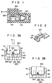
- FIG. 1 An example of a conventional insulation-displacement connector is shown in Fig. 1, and includes housing 100 with connection terminal 200 therewithin. At one end of connection terminal 200, insulation-displacement contact section 210 is formed, and is brought into contact with a conductor in a cable (not shown). At the other end of connection terminal 200, receptacle section 220 is formed, and is connected to a plug pin (not shown. At insulation-displacement contact section 210 of connection terminal 200, opening 211 and slot 212 communicating with opening are formed, as is shown in Fig. 2.
- Push member 300 made of an insulation material is snap-fitted into housing 100 such that projections 311, 312, formed on the side surfaces of push member 300, engage first grooves 110, shown in Fig. 3A, which are formed on the inner surfaces of the housing.
- Cable 400 is inserted, with cable insulation 410, through insertion hole 500 located between recess 320 of push member 300 and opening 211 of terminal 200, as is shown in Fig. 3A.
- a suitable tool such as a pair of pliers
- the cable insulation is displaced, so that conductor 420 of the cable is exposed and pinched in slot 212 of contact section 210, as is shown in Fig. 3B.
- projections 311, 312 of push member 300 abut against second grooves 120, as is shown in Fig. 3B.
- cable 400 is fixedly connected to connection terminal 200, via the exposed conductor 420.
- This conventional insulation-displacement connector comprises a housing in which three connection terminals are arranged in parallel relationship in order to receive a set of three parallel conductors each having an insulation layer. Each connection terminal has a downwardly-directed slot.
- the space within the housing is divided into three channels with the aid of two inner walls parallel to the opposite side walls. In said channels between said opposite side walls of the housing and the two inner walls respectively said three connection terminals are positioned on the bottom of the housing.
- the push member made of insulation material has a closed top and two opposite sides insertable into the housing. Within the space formed by the closed top and opposite sides a push element is located having three recesses evenly divided opposite the slots of the connection terminals of the three channels to receive the conductors. The three recesses each substantially have a shallow half circular form.
- the opposite inner surfaces of the side walls of the housing are each provided with a first rib, and a second rib, while the separate sides of the push member are each provided with first and second projections. These ribs cooperate with said projections on the separate sides of the push member when this push member is inserted into the housing.
- One object of the present invention is to provide an insulation-displacement connector which is markedly improved in relation to a conventional insulation-displacement connector.
- Another object of the present invention is to provide an insulation-displacement connector which, even if the cable is thin, assures a positive connection to a cable conductor, without the risk of the cable inadvertently slipping or dropping off the insertion hole.
- the invention aims to obviate the above mentioned problems with an insulation-displacement connector of the above mentioned type according to the invention such that the second engaging means are grooves provided on the opposite inner surfaces of the side walls of the housing near the bottom thereof, that the guide means are guiding grooves formed between the first and second engaging means, being first and second engaging grooves, on the opposite inner surfaces of the side walls of the housing that the guiding grooves are formed as wider guide grooves between first and second engaging grooves, that the recess in the push member opening toward the opening of the connection terminal is formed by two legs, which form said two opposite sides of the push member, and that the opening of the connection terminal is tapered, so that it aligns with the center of the recess, which has an inverted elongated U-shape, thus defining an insertion hole between said recess and said downwardly-directed opening, and that said projections are placed at the bottom of the sides of the push member.
- the cable is placed over the tapered opening of the connection terminal.
- the push member is pushed down over the cable so that the projections of the push member may be moved along the guide grooves.
- the cable is forced into the tapered opening of the connection terminal and is held there by the push member.
- the push member is further pushed with extra force, so that the cable is pushed into the slot of the connection terminal and the insulation layer of the cable is displaced to permit the exposed conductor to be connected to the connection terminal.
- the cable is temporarily held at the tapered opening of the connection terminal before it can be further pushed into the slot. This prevents the cable from inadvertently slipping or dropping off a connection terminal due to an impact.
- the push member is preferably made of an elastic insulation material, such as a plastic type, so that the pair of legs of the push member can be elastically deformed toward and away from each other.
- the projections of the legs may effectively be sharp-tipped in order to properly engage with the minute grooves which are formed as a knurled portion on the inner surfaces of the side wall of the housing.
- Figs. 4 and 5 show an insulation-displacement connector according to one embodiment of the present invention.
- the connector includes housing 10, connection terminals 20 located within the housing and push member 30 to be inserted into the housing through the open top of the housing.
- Inverted U-shaped recess 32 is formed on front surface 31 of push member 30.
- U-shaped recess 32 is so formed that its center aligns with tapered opening 21 of connection terminal 20.
- Projections 33, 34 are formed on either side of push member 30 such that they can engage with first engaging grooves 11 formed on the inner surface of the side walls 101 of housing 10, with insertion hole 50 defined between tapered opening 21 of connection terminal 20 and U-shaped recess 32 of push member 30.
- the size of insertion hole 50 is selected to allow the ready insertion of not only a thin cable but also a thick one.
- first grooves 11 of the housing Formed below first grooves 11 of the housing are guide grooves 12 which guide projections 33, 34. Guide grooves 12 allow the push member to be moved within a range of the width of the guide groove, when it is forced downward and its projections move beyond first engaging grooves 11.
- Push member 30 has a pair of legs 35, 36 with U-shaped recess 32 defined therebetween.
- the push member is preferably formed of plastic material so that the pair of legs can elastically deform inwardly or outwardly.
- the resultant push member allows its projections 33, 34 to be effectively snap-fitted into first grooves 11 and then into guide grooves 12 beyond the first grooves. With projections 33, 34 located in guide grooves 12, they are pushed firmly against the inner surface of guide grooves 12, by the elastic force of leg sections 35, 36, to allow push member 30 to be held in any desired position.
- Second engaging grooves 13 are formed adjacent to guide grooves 12, and are used to hold the cable in place, as is set forth below.
- the first grooves, second grooves and guide grooves extend in direction perpendicular to that in which push member is pushed into the housing.
- push member 30 is so set that its projections 33, 34 fit into first grooves 11, as is shown in Fig. 4.
- cable 40 is inserted into insertion hole 50 and placed on tapered opening 21.
- Push member 30 is pushed, for example, by hand, into guide grooves 12, as indicated by I in Fig. 6, with its projections clear of the first engaging groove, so that cable 40 is compressed over tapered opening 21 of connection terminal 20 and stopped at that position. Since projections 33, 34 abut against the inner surface of guide grooves 12, with a greater frictional force, there is no risk, even if the pushing force (such as hand grip force) is released from push member 30, that the push member will slip upwardly due to the elastic recovery force exerted by insulation layer 41.
- the pushing force such as hand grip force
- push member 30 With cable 40 so held, push member 30 is forcibly pushed by, for example, a pair of pliers, in the direction indicated by arrow P so that, as indicated by II in Fig. 6, projections 33, 34 snap-fit into second engaging grooves 13, to allow conductor 42 to be pinched in contact with slot 22 of connection terminal 20, with insulation layer 41 displaced.
- the cable Before this step, the cable is already in contact with push member 30 and, for this reason, the cable will assuredly be guided into the slot of connection terminal 20, by the push member.
- Fig. 7 shows an insulation-displacement connector according another embodiment of this invention.
- a number of minute grooves 14a, 14b, ... are formed, as a knurled portion, over a range of the width of guide grooves 12.
- Sharp-tipped projections 33, 34 may effectively be formed on push member 30 so as to allow them to be hooked onto the respective minute grooves.
Landscapes
- Connections By Means Of Piercing Elements, Nuts, Or Screws (AREA)
- Multi-Conductor Connections (AREA)
- Connector Housings Or Holding Contact Members (AREA)
Description
- The invention relates to an insulation-displacement connector adapted to be connected to a cable having a conductor with an insulation layer covering thereon, which connector displaces the insulation layer and pinches the conductor in a slot of a connection terminal in order to asure an electrical connection between the conductor and the connection terminal such as is further indicated in the heading of the main claim.
- An example of a conventional insulation-displacement connector is shown in Fig. 1, and includes
housing 100 withconnection terminal 200 therewithin. At one end ofconnection terminal 200, insulation-displacement contact section 210 is formed, and is brought into contact with a conductor in a cable (not shown). At the other end ofconnection terminal 200,receptacle section 220 is formed, and is connected to a plug pin (not shown. At insulation-displacement contact section 210 ofconnection terminal 200, opening 211 andslot 212 communicating with opening are formed, as is shown in Fig. 2.Push member 300 made of an insulation material is snap-fitted intohousing 100 such thatprojections push member 300, engagefirst grooves 110, shown in Fig. 3A, which are formed on the inner surfaces of the housing. -
Cable 400 is inserted, withcable insulation 410, throughinsertion hole 500 located betweenrecess 320 ofpush member 300 and opening 211 ofterminal 200, as is shown in Fig. 3A. By using a suitable tool, such as a pair of pliers, to forcefully insertpush member 300 intohousing 100, in the direction indicated by an arrow P in Fig. 3A, the cable insulation is displaced, so thatconductor 420 of the cable is exposed and pinched inslot 212 ofcontact section 210, as is shown in Fig. 3B. In this state,projections push member 300 abut againstsecond grooves 120, as is shown in Fig. 3B. In this way,cable 400 is fixedly connected toconnection terminal 200, via the exposedconductor 420. - In the aforementioned insulation-displacement connector, however, the push member presses strongly against the outer surface of the cable, upon
member 300 being forcefully inserted intohousing 100 and, for this reason, there is a risk that the cable will inadvertently slip off or be shifted relative to the insertion hole, as a result of the impact exerted bymember 300. This problem arises, in particular when the cable is thin. - Another example of a conventional insulation-displacement connector, as reflected in the heading of the main claim, is indicated in DE-A-3009675. This conventional insulation-displacement connector comprises a housing in which three connection terminals are arranged in parallel relationship in order to receive a set of three parallel conductors each having an insulation layer. Each connection terminal has a downwardly-directed slot. The space within the housing is divided into three channels with the aid of two inner walls parallel to the opposite side walls. In said channels between said opposite side walls of the housing and the two inner walls respectively said three connection terminals are positioned on the bottom of the housing. The push member made of insulation material has a closed top and two opposite sides insertable into the housing. Within the space formed by the closed top and opposite sides a push element is located having three recesses evenly divided opposite the slots of the connection terminals of the three channels to receive the conductors. The three recesses each substantially have a shallow half circular form.
- The opposite inner surfaces of the side walls of the housing are each provided with a first rib, and a second rib, while the separate sides of the push member are each provided with first and second projections. These ribs cooperate with said projections on the separate sides of the push member when this push member is inserted into the housing.
- One object of the present invention is to provide an insulation-displacement connector which is markedly improved in relation to a conventional insulation-displacement connector.
- Another object of the present invention is to provide an insulation-displacement connector which, even if the cable is thin, assures a positive connection to a cable conductor, without the risk of the cable inadvertently slipping or dropping off the insertion hole.
- The invention aims to obviate the above mentioned problems with an insulation-displacement connector of the above mentioned type according to the invention such that the second engaging means are grooves provided on the opposite inner surfaces of the side walls of the housing near the bottom thereof, that the guide means are guiding grooves formed between the first and second engaging means, being first and second engaging grooves, on the opposite inner surfaces of the side walls of the housing that the guiding grooves are formed as wider guide grooves between first and second engaging grooves, that the recess in the push member opening toward the opening of the connection terminal is formed by two legs, which form said two opposite sides of the push member, and that the opening of the connection terminal is tapered, so that it aligns with the center of the recess, which has an inverted elongated U-shape, thus defining an insertion hole between said recess and said downwardly-directed opening, and that said projections are placed at the bottom of the sides of the push member.
- In the connector of the present invention, the cable is placed over the tapered opening of the connection terminal. The push member is pushed down over the cable so that the projections of the push member may be moved along the guide grooves. In this state, the cable is forced into the tapered opening of the connection terminal and is held there by the push member. Then the push member is further pushed with extra force, so that the cable is pushed into the slot of the connection terminal and the insulation layer of the cable is displaced to permit the exposed conductor to be connected to the connection terminal.
- The cable is temporarily held at the tapered opening of the connection terminal before it can be further pushed into the slot. This prevents the cable from inadvertently slipping or dropping off a connection terminal due to an impact.
- The push member is preferably made of an elastic insulation material, such as a plastic type, so that the pair of legs of the push member can be elastically deformed toward and away from each other.
- The projections of the legs may effectively be sharp-tipped in order to properly engage with the minute grooves which are formed as a knurled portion on the inner surfaces of the side wall of the housing.
- This invention can be more fully understood from the following detailed description when taken in conjunction with the accompanying drawings, in which:
- Fig. 1 is a cross-sectional view showing a conventional insulation-displacement connector;
- Fig. 2 is a perspective view showing a connector terminal in the connector of Fig. 1;
- Figs. 3A and 3B are front views showing the connector as seen in the direction indicated by an arrow III in Fig. 1;
- Fig. 4 is a front view showing an insulation-displacement connector according to one embodiment of this invention;
- Fig. 5 is a perspective view of the connector of Fig. 4;
- Fig. 6 is a front view of the connector of Fig. 4, explaining the manner in which the connection is used; and
- Fig. 7 is a view showing an insulation-displacement connector according to another embodiment of the present invention.
- Figs. 4 and 5 show an insulation-displacement connector according to one embodiment of the present invention. The connector includes
housing 10,connection terminals 20 located within the housing andpush member 30 to be inserted into the housing through the open top of the housing. Inverted U-shapedrecess 32 is formed onfront surface 31 ofpush member 30. U-shapedrecess 32 is so formed that its center aligns withtapered opening 21 ofconnection terminal 20.Projections push member 30 such that they can engage with firstengaging grooves 11 formed on the inner surface of theside walls 101 ofhousing 10, withinsertion hole 50 defined betweentapered opening 21 ofconnection terminal 20 and U-shaped recess 32 ofpush member 30. The size ofinsertion hole 50 is selected to allow the ready insertion of not only a thin cable but also a thick one. - Formed below
first grooves 11 of the housing areguide grooves 12 which guideprojections Guide grooves 12 allow the push member to be moved within a range of the width of the guide groove, when it is forced downward and its projections move beyond firstengaging grooves 11. -
Push member 30 has a pair oflegs 35, 36 withU-shaped recess 32 defined therebetween. The push member is preferably formed of plastic material so that the pair of legs can elastically deform inwardly or outwardly. The resultant push member allows itsprojections first grooves 11 and then intoguide grooves 12 beyond the first grooves. Withprojections guide grooves 12, they are pushed firmly against the inner surface ofguide grooves 12, by the elastic force ofleg sections 35, 36, to allowpush member 30 to be held in any desired position. - Second
engaging grooves 13 are formed adjacent to guidegrooves 12, and are used to hold the cable in place, as is set forth below. The first grooves, second grooves and guide grooves extend in direction perpendicular to that in which push member is pushed into the housing. - Firstly,
push member 30 is so set that itsprojections first grooves 11, as is shown in Fig. 4. Then,cable 40 is inserted intoinsertion hole 50 and placed ontapered opening 21.Push member 30 is pushed, for example, by hand, intoguide grooves 12, as indicated by I in Fig. 6, with its projections clear of the first engaging groove, so thatcable 40 is compressed overtapered opening 21 ofconnection terminal 20 and stopped at that position. Sinceprojections guide grooves 12, with a greater frictional force, there is no risk, even if the pushing force (such as hand grip force) is released frompush member 30, that the push member will slip upwardly due to the elastic recovery force exerted byinsulation layer 41. It should be noted that various cables of respective different diameters may be used, due to guidegrooves 12 being formed as wider guide grooves between first engaginggrooves 11 and second engaginggrooves 13. As a result,cable 40, even if smaller in diameter, can be positively held over taperedopening 21. - With
cable 40 so held,push member 30 is forcibly pushed by, for example, a pair of pliers, in the direction indicated by arrow P so that, as indicated by II in Fig. 6,projections grooves 13, to allowconductor 42 to be pinched in contact withslot 22 ofconnection terminal 20, withinsulation layer 41 displaced. Before this step, the cable is already in contact withpush member 30 and, for this reason, the cable will assuredly be guided into the slot ofconnection terminal 20, by the push member. - Fig. 7 shows an insulation-displacement connector according another embodiment of this invention. A number of
minute grooves guide grooves 12. Sharp-tippedprojections push member 30 so as to allow them to be hooked onto the respective minute grooves.
Claims (1)
- An insulation-displacement connector adapted to be connected to a cable (40) having a conductor (42) with an insulation layer (41) covering thereon, comprising:(A) a housing (10) made of an insulation material, having two opposite side walls (101), an open top, and an open front;(B) a connection terminal (20) arranged within the housing (10) and having a downwardly-directed opening (21) with a slot (22) communicating therewith; and(C) a push member (30) made of an insulation material, having a closed top and two opposite sides insertable into the housing, and having a recess (32) located opposite said opening (21) of said connection terminal and projections (33, 34) formed on the respective sides and facing the inner surfaces of said side walls (101) of said housing, and inserted into said housing from said open top of said housing, said push member with its recess (32) being capable to push the cable (40) placed over the opening (21) of the connection terminal (20), so that the cable is pushed into the slot (22) of the connection terminal in order to expose the conductor (42) for connection to the connection terminal, said housing (10) including(a) first engaging means (11) provided on the opposite inner surfaces of the side walls (101) of the housing and adapted to engage with the projections (33, 34) of the push member (30), with the cable (40) set over the opening (21) of the connection terminal so as to hold the push member relative to the housing;(b) second engaging means (13); and(c) guide means (12) adapted to guide the push member (30) to a position where the cable is held between the opening of the connection terminal (21,22) and the recess (32) of the push member (30) before the exposed conductor is connected to the connection terminal (20),
characterized in that the second engaging means (13) are grooves provided on the opposite inner surfaces of the side walls of the housing (10) near the bottom thereof,
that the guide means are guiding grooves (12) formed between the first and second engaging means, being first (11) and second (12) engaging grooves, on the opposite inner surfaces of the side walls (101) of the housing, the guiding grooves being formed as wider guide grooves (12) between first (11) and second (13) engaging grooves, and
that the recess (32) in the push member opening toward the opening (21) of the connection terminal is formed by two legs (35, 36), which form said two opposite sides of the push member (30), and that the opening (21) of the connection terminal is tapered, so that it aligns with the center of the recess (32), which has an inverted elongated U-shape (see fig. 4), thus defining an insertion hole (50) between said recess (32) and said downwardly-directed opening (21), said projections (33, 34) being placed at the bottom of the sides of the push member.
Applications Claiming Priority (2)
| Application Number | Priority Date | Filing Date | Title |
|---|---|---|---|
| JP1986019970U JPS62131368U (en) | 1986-02-14 | 1986-02-14 | |
| JP19970/86U | 1986-02-14 |
Publications (2)
| Publication Number | Publication Date |
|---|---|
| EP0234639A1 EP0234639A1 (en) | 1987-09-02 |
| EP0234639B1 true EP0234639B1 (en) | 1994-10-26 |
Family
ID=12014051
Family Applications (1)
| Application Number | Title | Priority Date | Filing Date |
|---|---|---|---|
| EP87200208A Expired - Lifetime EP0234639B1 (en) | 1986-02-14 | 1987-02-11 | Insulation-displacement connector |
Country Status (4)
| Country | Link |
|---|---|
| EP (1) | EP0234639B1 (en) |
| JP (1) | JPS62131368U (en) |
| KR (1) | KR920000714B1 (en) |
| DE (1) | DE3750678T2 (en) |
Families Citing this family (8)
| Publication number | Priority date | Publication date | Assignee | Title |
|---|---|---|---|---|
| FR2691846B1 (en) * | 1992-05-26 | 1995-12-22 | Jacques Nozick | ELECTRIC SOCKET WITH SELF-INSULATING CONTACT. |
| US5547391A (en) * | 1993-03-11 | 1996-08-20 | Molex Incorporated | Commoning electrical connector |
| WO1994024727A1 (en) * | 1993-04-13 | 1994-10-27 | Siemens Aktiengesellschaft | Actuators or sensors for connecting a bus line |
| WO1994024725A1 (en) * | 1993-04-14 | 1994-10-27 | Siemens Aktiengesellschaft | Module for the connection of actuators and/or sensors |
| CA2135578A1 (en) * | 1993-11-17 | 1995-05-18 | Julio F. Rodrigues | Electrical connector having a conductor holding block |
| DE4442673A1 (en) * | 1994-11-30 | 1996-06-05 | Siemens Ag | Electrical potential distributor using insulation displacement technology |
| JP5026884B2 (en) * | 2007-08-04 | 2012-09-19 | 株式会社森精機製作所 | Machine tool with automatic tool changer |
| HUP1400211A2 (en) | 2014-04-24 | 2015-11-30 | Jozsef Laszlo Baran | Method for manufacturing insulation displacement connector device and insulation displacement connector device |
Family Cites Families (4)
| Publication number | Priority date | Publication date | Assignee | Title |
|---|---|---|---|---|
| AT312726B (en) * | 1970-11-27 | 1974-01-10 | Assmann Geb | Solderless wire connector |
| GB1554103A (en) * | 1975-07-22 | 1979-10-17 | Bicc Ltd | Electrical connectors |
| ZA80400B (en) * | 1979-03-12 | 1981-05-27 | Minnesota Mining & Mfg | Wire cutting electrical connector |
| JPS603743B2 (en) * | 1980-07-05 | 1985-01-30 | モレックス・インコ−ポレ−テッド | Electrical connector for ribbon cable |
-
1986
- 1986-02-14 JP JP1986019970U patent/JPS62131368U/ja active Pending
-
1987
- 1987-02-11 DE DE3750678T patent/DE3750678T2/en not_active Expired - Fee Related
- 1987-02-11 EP EP87200208A patent/EP0234639B1/en not_active Expired - Lifetime
- 1987-02-13 KR KR1019870001203A patent/KR920000714B1/en not_active Expired
Also Published As
| Publication number | Publication date |
|---|---|
| DE3750678D1 (en) | 1994-12-01 |
| EP0234639A1 (en) | 1987-09-02 |
| KR870008410A (en) | 1987-09-26 |
| DE3750678T2 (en) | 1995-06-01 |
| KR920000714B1 (en) | 1992-01-20 |
| JPS62131368U (en) | 1987-08-19 |
Similar Documents
| Publication | Publication Date | Title |
|---|---|---|
| US4834677A (en) | Male and/or female electrical connectors | |
| US4897041A (en) | Electrical connector having a cable terminating cover retention system and a strain relief therefor | |
| EP0001159B1 (en) | Electrical connector | |
| EP0021731B1 (en) | Electrical contact member and connector including such contact members | |
| EP0239422A1 (en) | Electrical connector for flexible flat cable | |
| EP0817313B1 (en) | Electrical insulation displacement connector assembly with cable clamping means | |
| US4527852A (en) | Multigauge insulation displacement connector and contacts therefor | |
| US4713020A (en) | Connector unit | |
| EP0650218B1 (en) | Cramping joint connector | |
| US4722699A (en) | Embedded wire-stripping connector for electrical equipment | |
| US4508410A (en) | Electrical termination system and connector member | |
| US4130329A (en) | Electrical connector assembly retention system | |
| EP0234639A1 (en) | Insulation-displacement connector | |
| EP0720258B1 (en) | Insulation displacement connector | |
| GB2080032A (en) | A plug for masking switching contacts | |
| EP4044379B1 (en) | Systems and methods for flat cable installation | |
| JPH059905B2 (en) | ||
| US4478470A (en) | Electrical contact | |
| USRE32898E (en) | Multigauge insulation displacement connector and contacts therefor | |
| JPH0689748A (en) | Electric connector | |
| US4090770A (en) | Connector cover construction | |
| JP3340325B2 (en) | Electrical connector with multiple rows of cables | |
| EP0446220B1 (en) | Electrical contact | |
| JPH0315180A (en) | Two piece connector and pressure joining method for flat cable | |
| US4360242A (en) | Self-fastening electrical connector |
Legal Events
| Date | Code | Title | Description |
|---|---|---|---|
| PUAI | Public reference made under article 153(3) epc to a published international application that has entered the european phase |
Free format text: ORIGINAL CODE: 0009012 |
|
| AK | Designated contracting states |
Kind code of ref document: A1 Designated state(s): DE FR GB IT |
|
| 17P | Request for examination filed |
Effective date: 19880302 |
|
| 17Q | First examination report despatched |
Effective date: 19910319 |
|
| GRAA | (expected) grant |
Free format text: ORIGINAL CODE: 0009210 |
|
| AK | Designated contracting states |
Kind code of ref document: B1 Designated state(s): DE FR GB IT |
|
| REF | Corresponds to: |
Ref document number: 3750678 Country of ref document: DE Date of ref document: 19941201 |
|
| ITF | It: translation for a ep patent filed | ||
| ET | Fr: translation filed | ||
| PLBE | No opposition filed within time limit |
Free format text: ORIGINAL CODE: 0009261 |
|
| STAA | Information on the status of an ep patent application or granted ep patent |
Free format text: STATUS: NO OPPOSITION FILED WITHIN TIME LIMIT |
|
| REG | Reference to a national code |
Ref country code: FR Ref legal event code: CD Ref country code: FR Ref legal event code: CA |
|
| REG | Reference to a national code |
Ref country code: FR Ref legal event code: TP |
|
| 26N | No opposition filed | ||
| PGFP | Annual fee paid to national office [announced via postgrant information from national office to epo] |
Ref country code: GB Payment date: 19990108 Year of fee payment: 13 |
|
| PGFP | Annual fee paid to national office [announced via postgrant information from national office to epo] |
Ref country code: FR Payment date: 19990204 Year of fee payment: 13 |
|
| PGFP | Annual fee paid to national office [announced via postgrant information from national office to epo] |
Ref country code: DE Payment date: 19990226 Year of fee payment: 13 |
|
| PG25 | Lapsed in a contracting state [announced via postgrant information from national office to epo] |
Ref country code: GB Free format text: LAPSE BECAUSE OF NON-PAYMENT OF DUE FEES Effective date: 20000211 |
|
| GBPC | Gb: european patent ceased through non-payment of renewal fee |
Effective date: 20000211 |
|
| PG25 | Lapsed in a contracting state [announced via postgrant information from national office to epo] |
Ref country code: FR Free format text: LAPSE BECAUSE OF NON-PAYMENT OF DUE FEES Effective date: 20001031 |
|
| PG25 | Lapsed in a contracting state [announced via postgrant information from national office to epo] |
Ref country code: DE Free format text: LAPSE BECAUSE OF NON-PAYMENT OF DUE FEES Effective date: 20001201 |
|
| REG | Reference to a national code |
Ref country code: FR Ref legal event code: ST |
|
| PG25 | Lapsed in a contracting state [announced via postgrant information from national office to epo] |
Ref country code: IT Free format text: LAPSE BECAUSE OF NON-PAYMENT OF DUE FEES Effective date: 20050211 |