EP0233318A2 - Apparatus for sealing packages - Google Patents
Apparatus for sealing packages Download PDFInfo
- Publication number
- EP0233318A2 EP0233318A2 EP86114141A EP86114141A EP0233318A2 EP 0233318 A2 EP0233318 A2 EP 0233318A2 EP 86114141 A EP86114141 A EP 86114141A EP 86114141 A EP86114141 A EP 86114141A EP 0233318 A2 EP0233318 A2 EP 0233318A2
- Authority
- EP
- European Patent Office
- Prior art keywords
- sealing
- web
- knife blade
- slide arm
- sealing head
- Prior art date
- Legal status (The legal status is an assumption and is not a legal conclusion. Google has not performed a legal analysis and makes no representation as to the accuracy of the status listed.)
- Granted
Links
Images
Classifications
-
- B—PERFORMING OPERATIONS; TRANSPORTING
- B65—CONVEYING; PACKING; STORING; HANDLING THIN OR FILAMENTARY MATERIAL
- B65B—MACHINES, APPARATUS OR DEVICES FOR, OR METHODS OF, PACKAGING ARTICLES OR MATERIALS; UNPACKING
- B65B51/00—Devices for, or methods of, sealing or securing package folds or closures; Devices for gathering or twisting wrappers, or necks of bags
- B65B51/10—Applying or generating heat or pressure or combinations thereof
- B65B51/26—Devices specially adapted for producing transverse or longitudinal seams in webs or tubes
- B65B51/30—Devices, e.g. jaws, for applying pressure and heat, e.g. for subdividing filled tubes
- B65B51/303—Devices, e.g. jaws, for applying pressure and heat, e.g. for subdividing filled tubes reciprocating along only one axis
-
- B—PERFORMING OPERATIONS; TRANSPORTING
- B65—CONVEYING; PACKING; STORING; HANDLING THIN OR FILAMENTARY MATERIAL
- B65B—MACHINES, APPARATUS OR DEVICES FOR, OR METHODS OF, PACKAGING ARTICLES OR MATERIALS; UNPACKING
- B65B51/00—Devices for, or methods of, sealing or securing package folds or closures; Devices for gathering or twisting wrappers, or necks of bags
- B65B51/10—Applying or generating heat or pressure or combinations thereof
-
- B—PERFORMING OPERATIONS; TRANSPORTING
- B29—WORKING OF PLASTICS; WORKING OF SUBSTANCES IN A PLASTIC STATE IN GENERAL
- B29C—SHAPING OR JOINING OF PLASTICS; SHAPING OF MATERIAL IN A PLASTIC STATE, NOT OTHERWISE PROVIDED FOR; AFTER-TREATMENT OF THE SHAPED PRODUCTS, e.g. REPAIRING
- B29C65/00—Joining or sealing of preformed parts, e.g. welding of plastics materials; Apparatus therefor
- B29C65/02—Joining or sealing of preformed parts, e.g. welding of plastics materials; Apparatus therefor by heating, with or without pressure
-
- B—PERFORMING OPERATIONS; TRANSPORTING
- B29—WORKING OF PLASTICS; WORKING OF SUBSTANCES IN A PLASTIC STATE IN GENERAL
- B29C—SHAPING OR JOINING OF PLASTICS; SHAPING OF MATERIAL IN A PLASTIC STATE, NOT OTHERWISE PROVIDED FOR; AFTER-TREATMENT OF THE SHAPED PRODUCTS, e.g. REPAIRING
- B29C65/00—Joining or sealing of preformed parts, e.g. welding of plastics materials; Apparatus therefor
- B29C65/74—Joining or sealing of preformed parts, e.g. welding of plastics materials; Apparatus therefor by welding and severing, or by joining and severing, the severing being performed in the area to be joined, next to the area to be joined, in the joint area or next to the joint area
- B29C65/745—Joining or sealing of preformed parts, e.g. welding of plastics materials; Apparatus therefor by welding and severing, or by joining and severing, the severing being performed in the area to be joined, next to the area to be joined, in the joint area or next to the joint area using a single unit having both a severing tool and a welding tool
- B29C65/7451—Joining or sealing of preformed parts, e.g. welding of plastics materials; Apparatus therefor by welding and severing, or by joining and severing, the severing being performed in the area to be joined, next to the area to be joined, in the joint area or next to the joint area using a single unit having both a severing tool and a welding tool the severing tool and the welding tool being movable with respect to one-another
-
- B—PERFORMING OPERATIONS; TRANSPORTING
- B29—WORKING OF PLASTICS; WORKING OF SUBSTANCES IN A PLASTIC STATE IN GENERAL
- B29C—SHAPING OR JOINING OF PLASTICS; SHAPING OF MATERIAL IN A PLASTIC STATE, NOT OTHERWISE PROVIDED FOR; AFTER-TREATMENT OF THE SHAPED PRODUCTS, e.g. REPAIRING
- B29C66/00—General aspects of processes or apparatus for joining preformed parts
- B29C66/01—General aspects dealing with the joint area or with the area to be joined
- B29C66/05—Particular design of joint configurations
- B29C66/10—Particular design of joint configurations particular design of the joint cross-sections
- B29C66/11—Joint cross-sections comprising a single joint-segment, i.e. one of the parts to be joined comprising a single joint-segment in the joint cross-section
- B29C66/112—Single lapped joints
- B29C66/1122—Single lap to lap joints, i.e. overlap joints
-
- B—PERFORMING OPERATIONS; TRANSPORTING
- B29—WORKING OF PLASTICS; WORKING OF SUBSTANCES IN A PLASTIC STATE IN GENERAL
- B29C—SHAPING OR JOINING OF PLASTICS; SHAPING OF MATERIAL IN A PLASTIC STATE, NOT OTHERWISE PROVIDED FOR; AFTER-TREATMENT OF THE SHAPED PRODUCTS, e.g. REPAIRING
- B29C66/00—General aspects of processes or apparatus for joining preformed parts
- B29C66/01—General aspects dealing with the joint area or with the area to be joined
- B29C66/05—Particular design of joint configurations
- B29C66/10—Particular design of joint configurations particular design of the joint cross-sections
- B29C66/13—Single flanged joints; Fin-type joints; Single hem joints; Edge joints; Interpenetrating fingered joints; Other specific particular designs of joint cross-sections not provided for in groups B29C66/11 - B29C66/12
- B29C66/133—Fin-type joints, the parts to be joined being flexible
-
- B—PERFORMING OPERATIONS; TRANSPORTING
- B29—WORKING OF PLASTICS; WORKING OF SUBSTANCES IN A PLASTIC STATE IN GENERAL
- B29C—SHAPING OR JOINING OF PLASTICS; SHAPING OF MATERIAL IN A PLASTIC STATE, NOT OTHERWISE PROVIDED FOR; AFTER-TREATMENT OF THE SHAPED PRODUCTS, e.g. REPAIRING
- B29C66/00—General aspects of processes or apparatus for joining preformed parts
- B29C66/40—General aspects of joining substantially flat articles, e.g. plates, sheets or web-like materials; Making flat seams in tubular or hollow articles; Joining single elements to substantially flat surfaces
- B29C66/41—Joining substantially flat articles ; Making flat seams in tubular or hollow articles
- B29C66/43—Joining a relatively small portion of the surface of said articles
- B29C66/431—Joining the articles to themselves
- B29C66/4312—Joining the articles to themselves for making flat seams in tubular or hollow articles, e.g. transversal seams
-
- B—PERFORMING OPERATIONS; TRANSPORTING
- B29—WORKING OF PLASTICS; WORKING OF SUBSTANCES IN A PLASTIC STATE IN GENERAL
- B29C—SHAPING OR JOINING OF PLASTICS; SHAPING OF MATERIAL IN A PLASTIC STATE, NOT OTHERWISE PROVIDED FOR; AFTER-TREATMENT OF THE SHAPED PRODUCTS, e.g. REPAIRING
- B29C66/00—General aspects of processes or apparatus for joining preformed parts
- B29C66/40—General aspects of joining substantially flat articles, e.g. plates, sheets or web-like materials; Making flat seams in tubular or hollow articles; Joining single elements to substantially flat surfaces
- B29C66/41—Joining substantially flat articles ; Making flat seams in tubular or hollow articles
- B29C66/43—Joining a relatively small portion of the surface of said articles
- B29C66/432—Joining a relatively small portion of the surface of said articles for making tubular articles or closed loops, e.g. by joining several sheets ; for making hollow articles or hollow preforms
- B29C66/4322—Joining a relatively small portion of the surface of said articles for making tubular articles or closed loops, e.g. by joining several sheets ; for making hollow articles or hollow preforms by joining a single sheet to itself
-
- B—PERFORMING OPERATIONS; TRANSPORTING
- B29—WORKING OF PLASTICS; WORKING OF SUBSTANCES IN A PLASTIC STATE IN GENERAL
- B29C—SHAPING OR JOINING OF PLASTICS; SHAPING OF MATERIAL IN A PLASTIC STATE, NOT OTHERWISE PROVIDED FOR; AFTER-TREATMENT OF THE SHAPED PRODUCTS, e.g. REPAIRING
- B29C66/00—General aspects of processes or apparatus for joining preformed parts
- B29C66/40—General aspects of joining substantially flat articles, e.g. plates, sheets or web-like materials; Making flat seams in tubular or hollow articles; Joining single elements to substantially flat surfaces
- B29C66/41—Joining substantially flat articles ; Making flat seams in tubular or hollow articles
- B29C66/43—Joining a relatively small portion of the surface of said articles
- B29C66/432—Joining a relatively small portion of the surface of said articles for making tubular articles or closed loops, e.g. by joining several sheets ; for making hollow articles or hollow preforms
- B29C66/4324—Joining a relatively small portion of the surface of said articles for making tubular articles or closed loops, e.g. by joining several sheets ; for making hollow articles or hollow preforms for making closed loops, e.g. belts
-
- B—PERFORMING OPERATIONS; TRANSPORTING
- B29—WORKING OF PLASTICS; WORKING OF SUBSTANCES IN A PLASTIC STATE IN GENERAL
- B29C—SHAPING OR JOINING OF PLASTICS; SHAPING OF MATERIAL IN A PLASTIC STATE, NOT OTHERWISE PROVIDED FOR; AFTER-TREATMENT OF THE SHAPED PRODUCTS, e.g. REPAIRING
- B29C66/00—General aspects of processes or apparatus for joining preformed parts
- B29C66/70—General aspects of processes or apparatus for joining preformed parts characterised by the composition, physical properties or the structure of the material of the parts to be joined; Joining with non-plastics material
- B29C66/73—General aspects of processes or apparatus for joining preformed parts characterised by the composition, physical properties or the structure of the material of the parts to be joined; Joining with non-plastics material characterised by the intensive physical properties of the material of the parts to be joined, by the optical properties of the material of the parts to be joined, by the extensive physical properties of the parts to be joined, by the state of the material of the parts to be joined or by the material of the parts to be joined being a thermoplastic or a thermoset
- B29C66/739—General aspects of processes or apparatus for joining preformed parts characterised by the composition, physical properties or the structure of the material of the parts to be joined; Joining with non-plastics material characterised by the intensive physical properties of the material of the parts to be joined, by the optical properties of the material of the parts to be joined, by the extensive physical properties of the parts to be joined, by the state of the material of the parts to be joined or by the material of the parts to be joined being a thermoplastic or a thermoset characterised by the material of the parts to be joined being a thermoplastic or a thermoset
- B29C66/7392—General aspects of processes or apparatus for joining preformed parts characterised by the composition, physical properties or the structure of the material of the parts to be joined; Joining with non-plastics material characterised by the intensive physical properties of the material of the parts to be joined, by the optical properties of the material of the parts to be joined, by the extensive physical properties of the parts to be joined, by the state of the material of the parts to be joined or by the material of the parts to be joined being a thermoplastic or a thermoset characterised by the material of the parts to be joined being a thermoplastic or a thermoset characterised by the material of at least one of the parts being a thermoplastic
- B29C66/73921—General aspects of processes or apparatus for joining preformed parts characterised by the composition, physical properties or the structure of the material of the parts to be joined; Joining with non-plastics material characterised by the intensive physical properties of the material of the parts to be joined, by the optical properties of the material of the parts to be joined, by the extensive physical properties of the parts to be joined, by the state of the material of the parts to be joined or by the material of the parts to be joined being a thermoplastic or a thermoset characterised by the material of the parts to be joined being a thermoplastic or a thermoset characterised by the material of at least one of the parts being a thermoplastic characterised by the materials of both parts being thermoplastics
-
- B—PERFORMING OPERATIONS; TRANSPORTING
- B29—WORKING OF PLASTICS; WORKING OF SUBSTANCES IN A PLASTIC STATE IN GENERAL
- B29C—SHAPING OR JOINING OF PLASTICS; SHAPING OF MATERIAL IN A PLASTIC STATE, NOT OTHERWISE PROVIDED FOR; AFTER-TREATMENT OF THE SHAPED PRODUCTS, e.g. REPAIRING
- B29C66/00—General aspects of processes or apparatus for joining preformed parts
- B29C66/80—General aspects of machine operations or constructions and parts thereof
- B29C66/81—General aspects of the pressing elements, i.e. the elements applying pressure on the parts to be joined in the area to be joined, e.g. the welding jaws or clamps
- B29C66/814—General aspects of the pressing elements, i.e. the elements applying pressure on the parts to be joined in the area to be joined, e.g. the welding jaws or clamps characterised by the design of the pressing elements, e.g. of the welding jaws or clamps
- B29C66/8141—General aspects of the pressing elements, i.e. the elements applying pressure on the parts to be joined in the area to be joined, e.g. the welding jaws or clamps characterised by the design of the pressing elements, e.g. of the welding jaws or clamps characterised by the surface geometry of the part of the pressing elements, e.g. welding jaws or clamps, coming into contact with the parts to be joined
- B29C66/81411—General aspects of the pressing elements, i.e. the elements applying pressure on the parts to be joined in the area to be joined, e.g. the welding jaws or clamps characterised by the design of the pressing elements, e.g. of the welding jaws or clamps characterised by the surface geometry of the part of the pressing elements, e.g. welding jaws or clamps, coming into contact with the parts to be joined characterised by its cross-section, e.g. transversal or longitudinal, being non-flat
- B29C66/81415—General aspects of the pressing elements, i.e. the elements applying pressure on the parts to be joined in the area to be joined, e.g. the welding jaws or clamps characterised by the design of the pressing elements, e.g. of the welding jaws or clamps characterised by the surface geometry of the part of the pressing elements, e.g. welding jaws or clamps, coming into contact with the parts to be joined characterised by its cross-section, e.g. transversal or longitudinal, being non-flat being bevelled
- B29C66/81417—General aspects of the pressing elements, i.e. the elements applying pressure on the parts to be joined in the area to be joined, e.g. the welding jaws or clamps characterised by the design of the pressing elements, e.g. of the welding jaws or clamps characterised by the surface geometry of the part of the pressing elements, e.g. welding jaws or clamps, coming into contact with the parts to be joined characterised by its cross-section, e.g. transversal or longitudinal, being non-flat being bevelled being V-shaped
-
- B—PERFORMING OPERATIONS; TRANSPORTING
- B29—WORKING OF PLASTICS; WORKING OF SUBSTANCES IN A PLASTIC STATE IN GENERAL
- B29C—SHAPING OR JOINING OF PLASTICS; SHAPING OF MATERIAL IN A PLASTIC STATE, NOT OTHERWISE PROVIDED FOR; AFTER-TREATMENT OF THE SHAPED PRODUCTS, e.g. REPAIRING
- B29C66/00—General aspects of processes or apparatus for joining preformed parts
- B29C66/80—General aspects of machine operations or constructions and parts thereof
- B29C66/81—General aspects of the pressing elements, i.e. the elements applying pressure on the parts to be joined in the area to be joined, e.g. the welding jaws or clamps
- B29C66/814—General aspects of the pressing elements, i.e. the elements applying pressure on the parts to be joined in the area to be joined, e.g. the welding jaws or clamps characterised by the design of the pressing elements, e.g. of the welding jaws or clamps
- B29C66/8141—General aspects of the pressing elements, i.e. the elements applying pressure on the parts to be joined in the area to be joined, e.g. the welding jaws or clamps characterised by the design of the pressing elements, e.g. of the welding jaws or clamps characterised by the surface geometry of the part of the pressing elements, e.g. welding jaws or clamps, coming into contact with the parts to be joined
- B29C66/81411—General aspects of the pressing elements, i.e. the elements applying pressure on the parts to be joined in the area to be joined, e.g. the welding jaws or clamps characterised by the design of the pressing elements, e.g. of the welding jaws or clamps characterised by the surface geometry of the part of the pressing elements, e.g. welding jaws or clamps, coming into contact with the parts to be joined characterised by its cross-section, e.g. transversal or longitudinal, being non-flat
- B29C66/81421—General aspects of the pressing elements, i.e. the elements applying pressure on the parts to be joined in the area to be joined, e.g. the welding jaws or clamps characterised by the design of the pressing elements, e.g. of the welding jaws or clamps characterised by the surface geometry of the part of the pressing elements, e.g. welding jaws or clamps, coming into contact with the parts to be joined characterised by its cross-section, e.g. transversal or longitudinal, being non-flat being convex or concave
- B29C66/81423—General aspects of the pressing elements, i.e. the elements applying pressure on the parts to be joined in the area to be joined, e.g. the welding jaws or clamps characterised by the design of the pressing elements, e.g. of the welding jaws or clamps characterised by the surface geometry of the part of the pressing elements, e.g. welding jaws or clamps, coming into contact with the parts to be joined characterised by its cross-section, e.g. transversal or longitudinal, being non-flat being convex or concave being concave
-
- B—PERFORMING OPERATIONS; TRANSPORTING
- B29—WORKING OF PLASTICS; WORKING OF SUBSTANCES IN A PLASTIC STATE IN GENERAL
- B29C—SHAPING OR JOINING OF PLASTICS; SHAPING OF MATERIAL IN A PLASTIC STATE, NOT OTHERWISE PROVIDED FOR; AFTER-TREATMENT OF THE SHAPED PRODUCTS, e.g. REPAIRING
- B29C66/00—General aspects of processes or apparatus for joining preformed parts
- B29C66/80—General aspects of machine operations or constructions and parts thereof
- B29C66/81—General aspects of the pressing elements, i.e. the elements applying pressure on the parts to be joined in the area to be joined, e.g. the welding jaws or clamps
- B29C66/814—General aspects of the pressing elements, i.e. the elements applying pressure on the parts to be joined in the area to be joined, e.g. the welding jaws or clamps characterised by the design of the pressing elements, e.g. of the welding jaws or clamps
- B29C66/8141—General aspects of the pressing elements, i.e. the elements applying pressure on the parts to be joined in the area to be joined, e.g. the welding jaws or clamps characterised by the design of the pressing elements, e.g. of the welding jaws or clamps characterised by the surface geometry of the part of the pressing elements, e.g. welding jaws or clamps, coming into contact with the parts to be joined
- B29C66/81431—General aspects of the pressing elements, i.e. the elements applying pressure on the parts to be joined in the area to be joined, e.g. the welding jaws or clamps characterised by the design of the pressing elements, e.g. of the welding jaws or clamps characterised by the surface geometry of the part of the pressing elements, e.g. welding jaws or clamps, coming into contact with the parts to be joined comprising a single cavity, e.g. a groove
-
- B—PERFORMING OPERATIONS; TRANSPORTING
- B29—WORKING OF PLASTICS; WORKING OF SUBSTANCES IN A PLASTIC STATE IN GENERAL
- B29C—SHAPING OR JOINING OF PLASTICS; SHAPING OF MATERIAL IN A PLASTIC STATE, NOT OTHERWISE PROVIDED FOR; AFTER-TREATMENT OF THE SHAPED PRODUCTS, e.g. REPAIRING
- B29C66/00—General aspects of processes or apparatus for joining preformed parts
- B29C66/80—General aspects of machine operations or constructions and parts thereof
- B29C66/81—General aspects of the pressing elements, i.e. the elements applying pressure on the parts to be joined in the area to be joined, e.g. the welding jaws or clamps
- B29C66/816—General aspects of the pressing elements, i.e. the elements applying pressure on the parts to be joined in the area to be joined, e.g. the welding jaws or clamps characterised by the mounting of the pressing elements, e.g. of the welding jaws or clamps
- B29C66/8161—General aspects of the pressing elements, i.e. the elements applying pressure on the parts to be joined in the area to be joined, e.g. the welding jaws or clamps characterised by the mounting of the pressing elements, e.g. of the welding jaws or clamps said pressing elements being supported or backed-up by springs or by resilient material
-
- B—PERFORMING OPERATIONS; TRANSPORTING
- B29—WORKING OF PLASTICS; WORKING OF SUBSTANCES IN A PLASTIC STATE IN GENERAL
- B29C—SHAPING OR JOINING OF PLASTICS; SHAPING OF MATERIAL IN A PLASTIC STATE, NOT OTHERWISE PROVIDED FOR; AFTER-TREATMENT OF THE SHAPED PRODUCTS, e.g. REPAIRING
- B29C66/00—General aspects of processes or apparatus for joining preformed parts
- B29C66/80—General aspects of machine operations or constructions and parts thereof
- B29C66/83—General aspects of machine operations or constructions and parts thereof characterised by the movement of the joining or pressing tools
- B29C66/832—Reciprocating joining or pressing tools
- B29C66/8322—Joining or pressing tools reciprocating along one axis
- B29C66/83221—Joining or pressing tools reciprocating along one axis cooperating reciprocating tools, each tool reciprocating along one axis
-
- B—PERFORMING OPERATIONS; TRANSPORTING
- B29—WORKING OF PLASTICS; WORKING OF SUBSTANCES IN A PLASTIC STATE IN GENERAL
- B29C—SHAPING OR JOINING OF PLASTICS; SHAPING OF MATERIAL IN A PLASTIC STATE, NOT OTHERWISE PROVIDED FOR; AFTER-TREATMENT OF THE SHAPED PRODUCTS, e.g. REPAIRING
- B29C66/00—General aspects of processes or apparatus for joining preformed parts
- B29C66/80—General aspects of machine operations or constructions and parts thereof
- B29C66/84—Specific machine types or machines suitable for specific applications
- B29C66/849—Packaging machines
-
- B—PERFORMING OPERATIONS; TRANSPORTING
- B65—CONVEYING; PACKING; STORING; HANDLING THIN OR FILAMENTARY MATERIAL
- B65B—MACHINES, APPARATUS OR DEVICES FOR, OR METHODS OF, PACKAGING ARTICLES OR MATERIALS; UNPACKING
- B65B13/00—Bundling articles
- B65B13/18—Details of, or auxiliary devices used in, bundling machines or bundling tools
- B65B13/24—Securing ends of binding material
- B65B13/32—Securing ends of binding material by welding, soldering, or heat-sealing; by applying adhesive
-
- B—PERFORMING OPERATIONS; TRANSPORTING
- B29—WORKING OF PLASTICS; WORKING OF SUBSTANCES IN A PLASTIC STATE IN GENERAL
- B29C—SHAPING OR JOINING OF PLASTICS; SHAPING OF MATERIAL IN A PLASTIC STATE, NOT OTHERWISE PROVIDED FOR; AFTER-TREATMENT OF THE SHAPED PRODUCTS, e.g. REPAIRING
- B29C65/00—Joining or sealing of preformed parts, e.g. welding of plastics materials; Apparatus therefor
- B29C65/02—Joining or sealing of preformed parts, e.g. welding of plastics materials; Apparatus therefor by heating, with or without pressure
- B29C65/08—Joining or sealing of preformed parts, e.g. welding of plastics materials; Apparatus therefor by heating, with or without pressure using ultrasonic vibrations
-
- B—PERFORMING OPERATIONS; TRANSPORTING
- B29—WORKING OF PLASTICS; WORKING OF SUBSTANCES IN A PLASTIC STATE IN GENERAL
- B29C—SHAPING OR JOINING OF PLASTICS; SHAPING OF MATERIAL IN A PLASTIC STATE, NOT OTHERWISE PROVIDED FOR; AFTER-TREATMENT OF THE SHAPED PRODUCTS, e.g. REPAIRING
- B29C65/00—Joining or sealing of preformed parts, e.g. welding of plastics materials; Apparatus therefor
- B29C65/74—Joining or sealing of preformed parts, e.g. welding of plastics materials; Apparatus therefor by welding and severing, or by joining and severing, the severing being performed in the area to be joined, next to the area to be joined, in the joint area or next to the joint area
- B29C65/743—Joining or sealing of preformed parts, e.g. welding of plastics materials; Apparatus therefor by welding and severing, or by joining and severing, the severing being performed in the area to be joined, next to the area to be joined, in the joint area or next to the joint area using the same tool for both joining and severing, said tool being monobloc or formed by several parts mounted together and forming a monobloc
- B29C65/7443—Joining or sealing of preformed parts, e.g. welding of plastics materials; Apparatus therefor by welding and severing, or by joining and severing, the severing being performed in the area to be joined, next to the area to be joined, in the joint area or next to the joint area using the same tool for both joining and severing, said tool being monobloc or formed by several parts mounted together and forming a monobloc by means of ultrasonic vibrations
-
- B—PERFORMING OPERATIONS; TRANSPORTING
- B29—WORKING OF PLASTICS; WORKING OF SUBSTANCES IN A PLASTIC STATE IN GENERAL
- B29C—SHAPING OR JOINING OF PLASTICS; SHAPING OF MATERIAL IN A PLASTIC STATE, NOT OTHERWISE PROVIDED FOR; AFTER-TREATMENT OF THE SHAPED PRODUCTS, e.g. REPAIRING
- B29C66/00—General aspects of processes or apparatus for joining preformed parts
- B29C66/70—General aspects of processes or apparatus for joining preformed parts characterised by the composition, physical properties or the structure of the material of the parts to be joined; Joining with non-plastics material
- B29C66/72—General aspects of processes or apparatus for joining preformed parts characterised by the composition, physical properties or the structure of the material of the parts to be joined; Joining with non-plastics material characterised by the structure of the material of the parts to be joined
- B29C66/723—General aspects of processes or apparatus for joining preformed parts characterised by the composition, physical properties or the structure of the material of the parts to be joined; Joining with non-plastics material characterised by the structure of the material of the parts to be joined being multi-layered
- B29C66/7232—General aspects of processes or apparatus for joining preformed parts characterised by the composition, physical properties or the structure of the material of the parts to be joined; Joining with non-plastics material characterised by the structure of the material of the parts to be joined being multi-layered comprising a non-plastics layer
- B29C66/72321—General aspects of processes or apparatus for joining preformed parts characterised by the composition, physical properties or the structure of the material of the parts to be joined; Joining with non-plastics material characterised by the structure of the material of the parts to be joined being multi-layered comprising a non-plastics layer consisting of metals or their alloys
-
- B—PERFORMING OPERATIONS; TRANSPORTING
- B29—WORKING OF PLASTICS; WORKING OF SUBSTANCES IN A PLASTIC STATE IN GENERAL
- B29C—SHAPING OR JOINING OF PLASTICS; SHAPING OF MATERIAL IN A PLASTIC STATE, NOT OTHERWISE PROVIDED FOR; AFTER-TREATMENT OF THE SHAPED PRODUCTS, e.g. REPAIRING
- B29C66/00—General aspects of processes or apparatus for joining preformed parts
- B29C66/70—General aspects of processes or apparatus for joining preformed parts characterised by the composition, physical properties or the structure of the material of the parts to be joined; Joining with non-plastics material
- B29C66/72—General aspects of processes or apparatus for joining preformed parts characterised by the composition, physical properties or the structure of the material of the parts to be joined; Joining with non-plastics material characterised by the structure of the material of the parts to be joined
- B29C66/723—General aspects of processes or apparatus for joining preformed parts characterised by the composition, physical properties or the structure of the material of the parts to be joined; Joining with non-plastics material characterised by the structure of the material of the parts to be joined being multi-layered
- B29C66/7232—General aspects of processes or apparatus for joining preformed parts characterised by the composition, physical properties or the structure of the material of the parts to be joined; Joining with non-plastics material characterised by the structure of the material of the parts to be joined being multi-layered comprising a non-plastics layer
- B29C66/72327—General aspects of processes or apparatus for joining preformed parts characterised by the composition, physical properties or the structure of the material of the parts to be joined; Joining with non-plastics material characterised by the structure of the material of the parts to be joined being multi-layered comprising a non-plastics layer consisting of natural products or their composites, not provided for in B29C66/72321 - B29C66/72324
- B29C66/72328—Paper
-
- B—PERFORMING OPERATIONS; TRANSPORTING
- B29—WORKING OF PLASTICS; WORKING OF SUBSTANCES IN A PLASTIC STATE IN GENERAL
- B29C—SHAPING OR JOINING OF PLASTICS; SHAPING OF MATERIAL IN A PLASTIC STATE, NOT OTHERWISE PROVIDED FOR; AFTER-TREATMENT OF THE SHAPED PRODUCTS, e.g. REPAIRING
- B29C66/00—General aspects of processes or apparatus for joining preformed parts
- B29C66/80—General aspects of machine operations or constructions and parts thereof
- B29C66/81—General aspects of the pressing elements, i.e. the elements applying pressure on the parts to be joined in the area to be joined, e.g. the welding jaws or clamps
- B29C66/816—General aspects of the pressing elements, i.e. the elements applying pressure on the parts to be joined in the area to be joined, e.g. the welding jaws or clamps characterised by the mounting of the pressing elements, e.g. of the welding jaws or clamps
- B29C66/8167—Quick change joining tools or surfaces
Definitions
- the present invention relates generally to the packaging of articles with a wrapping material, and more particularly to an apparatus for making an end seal on a package formed from a web of thermoplastic sheet material.
- Japanese Patent Laid-open Publication No. 60-45118 published on March 11, 1985 discloses an apparatus for binding together a multiplicity of elongate articles by means of a pair of thermoplastic binding webs or strips.
- the disclosed apparatus comprises a combined ultrasonic welder-cutter including a pair of opposed welding heads, one of which has an integral cutting ridge for simultaneously cutting both webs while also fastening together the webs at opposite sides of the line of severance. Since the cutting ridge is fixed and not adjustable in height, a problem would occur when bundling the articles with binding webs of non-uniform thicknesses.
- the cutting ridge penetrates the webs before the opposed welding heads force the webs into mutual sealing engagement with each other.
- the cutting ridge is heated to the same temperature as the welding heads with the result that fused web material tends to stick to the cutting edge. With this sticky or dirty cutting edge, a clear line of severance cannot be created.
- the present invention seeks to provide a package-sealing apparatus capable of making an end seal on a package without causing any of the foregoing difficulties associated with the prior apparatus.
- the present invention further seeks to provide an apparatus having a combined heat-sealing and cutting unit having structural features which make it possible to provide a pair of end seals on opposite sides of a clean line of severance even when subjected to a change in thickness of a packaging web of thermoplastic sheet material.
- an apparatus for making an end seal on a package formed from a web of thermoplastic sheet material comprising: a heat-sealing unit including a pair of opposed sealing heads relatively movable toward each other to join a region of overlap of the web, and a cutting unit associated with one of said sealing heads for severing the web, characterized in that each said sealing head has a pair of spaced sealing lands engageable with the web to fuse the overlapping region along a pair of spaced portions extending respectively in registry with said sealing lands, and a channel defined between said sealing lands, and that said cutting unit includes a knife blade reciprocably movable through said channel of said one sealing head into said channel of the other sealing head for severing the web along a non-fused intermediate portion of the overlapping region.
- the present invention is particularly useful when embodied in a package-sealing apparatus such as shown in Figure 1, generally indicated by the reference numeral 10.
- the apparatus 10 generally comprises a heat-sealing unit 11 and a cutting unit 12 associated with one of a pair of horizontally opposed sealing heads 13, 14 of the heat-sealing unit 11.
- the first sealing head 13 comprises a rectangular plate detachably connected to a front end of a first slide arm 15 by means of a pair of screws (not designated).
- the slide arm 15 is slidably mounted on a first guide block 16 secured to a non-illustrated frame of the apparatus 10.
- the sealing head 13 includes a pair of parallel spaced sealing lands 17 extending horizontally across the face thereof, and an elongate central aperture or channel 18 defined between the sealing lands 17.
- Each of the sealing lands 17 has a front surface coated with a film 19 of fluorine plastics.
- the slide arm 15 includes a generally L-shaped recess 20 for purposes described below.
- the recess 20 has one end connected with the channel 18 and the other end opening to an upper surface of the slide arm 15.
- the second sealing head 14 comprises a generally rectangular block of fluorine plastics and is fastened to a front end of a presser block 21 via a dovetail joint.
- the second sealing head 14 includes a pair of parallel spaced sealing lands 22, 22 extending horizontally across the face thereof, and a central channel 23 defined between the lands 22.
- the presser block 21 is slidably received in a recessed front end portion 24 of a second slide arm 25 and is slidably movable toward and away from the first sealing head 13 for a limited distance.
- a compression coil spring 26 is disposed between and acts between the slide arm 25 and the presser block 21 to urge the latter and hence the sealing head 14 toward the first sealing head 13.
- the presser block 21 has a stopper lug 27 disposed on a rear end thereof and projecting upwardly outwardly from the recessed portion 24.
- the stopper lug 27 is engageable with the slide arm 25 to limit reciprocating movement of the presser block 21.
- the slide arm 25 is slidably mounted on a second guide block 28 secured to the frame of the apparatus 10.
- the first and second slide arms 15, 28 are operatively connected with a suitable drive means, not shown, and they are driven by the drive means to move relatively toward and away from each other.
- the cutting unit 12 includes a generally L-shaped cutting knife 29 reciprocably received in the recess 20 in the first slide arm 15, and an actuator 30 mounted on the slide arm 15 for reciprocating the cutting knife 29.
- the cutting knife 29 includes a horizontal knife blade 31 movable through the channel 18 in the sealing head 13, and a vertical stem 32 projecting upwardly outwardly from the recess 20.
- the actuator 30 comprises a fluid-actuated cylinder, such as an air cylinder having a piston rod 33 connected to the stem 32 of the cutting knife 29.
- the cylinder 30 is supported by a bracket 34 secured to the slide arm 15.
- the knife blade 31 has a tapered, notched cutting edge 31a.
- At least one of the sealing heads 13, 14 is heated to a desired temperature by means of a suitable heating means 35 ( Figure 1), such as an electric resistance heating element generally composed of a nichrome wire, a high-frequency heating element, or an ultrasonic heating element.
- a suitable heating means 35 such as an electric resistance heating element generally composed of a nichrome wire, a high-frequency heating element, or an ultrasonic heating element.
- the electric supply to the heating element is interrupted when the cutting unit 12 is being actuated to sever the webs.
- the package-sealing apparatus 10 thus constructed is incorporated in a packaging or binding machine for fastening together a desired number of elongate articles F by a pair of binding strips or webs T, as shown in Figures 5A - 5C, 6 and 7A - 7 C .
- the binding machine includes a pair of opposed tape feeders A, A disposed above the respective sealing heads 13, 14 of the apparatus 10 for supplying a pair of continuous binding tapes T' downwardly toward the apparatus 10 across the path of movement of the sealing heads 13, 14.
- the elongate articles F to be fastened together comprise surface- type fastener tapes generally known as loop-and-hook fastener tapes.
- the binding tapes T' are made of thermoplastic synthetic resin, such as polyester, polyethylene, nylon or polyvinyl chloride. It is also possible to use a composite sheet material such as a resin-laminated paper or a resin-laminated aluminum foil which is composed of a non-resin substrate or web and a thermoplastic synthetic resin film overlying the web. In the latter case, a multi-layer seal is formed between the thermoplastic synthetic resin films.
- the apparatus 10 is operatively connected with the binding machine to move in timed relation to the tape feeders A, A and a non-illustrated fastener feeder of the binding machine.
- a pair of continuous thermoplastic binding tapes T', T', with their leading ends S fused together, is fed by the respective tape feeders A, A to extend downwardly through the path of movement of the sealing heads 13, 14 so that predetermined lengths of the respective binding tapes T', T' jointly take an untensioned gravity-formed upwardly open U-shape between the sealing heads 13, 14.
- the slide arms 15, 25 are actuated to move toward each other to grip the binding tapes T', T' by and between the sealing heads 13, 14, thereby enbracing the fastener tapes F with the lengths of the binding tapes T', as shown in Figure 5C.
- the sealing lands 17, 22 of the respective sealing heads 13, 14 are held into abutment with an overlapping region of the tapes T'.
- thermoplastic binding tapes T' are fused together along their portions extending in registry with the lands 17, 22 so that two vertically spaced joined portions or seals are formed between the binding tapes T', one on each side of a non-fused intermediate portion of the overlapping region extending in registry with the channels 17, 23 in the respective sealing heads 13, 14.
- the tension coil spring 26 continuously exerts a back tension or pressure on the presser block 21 to ensure that the binding tapes T' are brought into mutual sealing engagement with each other by and between the sealing head 13 and the spring-loaded sealing head 14.
- the spring 26 also functions to absorb a shock force applied thereto when the knife blade 31 abuts agaist the sealing head 14.
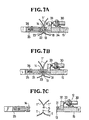
- the cylinder 30 is actuated to extend its piston rod 33 whereupon the knife blade 31 is moved to project outwardly from the sealing head through the channel 18 ( Figure 7A) into the channel 23 in the sealing head 14, thereby severing the binding tapes T' along the non-fused intermediate portion of the overlapping region of the tapes T'. Since the knife blade 31 is thermally isolated from the heated sealing heads 13, 14, a clean line of serverance can be created without causing a build-up of melted synthetic resin on the knife blade 31.
- the package-sealing apparatus 10 of the present invention is also suitable for continuous sealing of packages made on a form and fill packaging machien.
- a web of thermoplastic packaging film TU is formed into a tubular configuration.
- the formed tube of packaging film TU has an end seal S made transversely thereacross by the apparatus 10. After product is inserted into the tube TU, another end seal S 1 is made and a filed package P is severed by the apparatus 10. At the same time, a leading end seal S for the next package is formed.
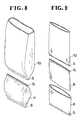
- FIG 9 shows two open wrapping tubes B, B with one end S closed by the apparatus 10.
- an empty tubular package similar to the package P shown in Figure 8, is severed transversely across an intermediate portion thereof.
Landscapes
- Engineering & Computer Science (AREA)
- Mechanical Engineering (AREA)
- Package Closures (AREA)
- Lining Or Joining Of Plastics Or The Like (AREA)
- Basic Packing Technique (AREA)
Abstract
Description
- The present invention relates generally to the packaging of articles with a wrapping material, and more particularly to an apparatus for making an end seal on a package formed from a web of thermoplastic sheet material.
- Japanese Patent Laid-open Publication No. 60-45118 published on March 11, 1985 discloses an apparatus for binding together a multiplicity of elongate articles by means of a pair of thermoplastic binding webs or strips. The disclosed apparatus comprises a combined ultrasonic welder-cutter including a pair of opposed welding heads, one of which has an integral cutting ridge for simultaneously cutting both webs while also fastening together the webs at opposite sides of the line of severance. Since the cutting ridge is fixed and not adjustable in height, a problem would occur when bundling the articles with binding webs of non-uniform thicknesses. More specifically, when the overlapped webs jointly have a thickness smaller than the height of the cutting ridge, the cutting ridge penetrates the webs before the opposed welding heads force the webs into mutual sealing engagement with each other. On the other hand, only an incomplete cutting is effected when the thickness of the doubled webs is larger than the height of the cutting ridge. Furthermore, due to the integral formation, the cutting ridge is heated to the same temperature as the welding heads with the result that fused web material tends to stick to the cutting edge. With this sticky or dirty cutting edge, a clear line of severance cannot be created.
- . The present invention seeks to provide a package-sealing apparatus capable of making an end seal on a package without causing any of the foregoing difficulties associated with the prior apparatus.
- The present invention further seeks to provide an apparatus having a combined heat-sealing and cutting unit having structural features which make it possible to provide a pair of end seals on opposite sides of a clean line of severance even when subjected to a change in thickness of a packaging web of thermoplastic sheet material.
- According to the present invention, there is provided an apparatus for making an end seal on a package formed from a web of thermoplastic sheet material, said apparatus comprising: a heat-sealing unit including a pair of opposed sealing heads relatively movable toward each other to join a region of overlap of the web, and a cutting unit associated with one of said sealing heads for severing the web, characterized in that each said sealing head has a pair of spaced sealing lands engageable with the web to fuse the overlapping region along a pair of spaced portions extending respectively in registry with said sealing lands, and a channel defined between said sealing lands, and that said cutting unit includes a knife blade reciprocably movable through said channel of said one sealing head into said channel of the other sealing head for severing the web along a non-fused intermediate portion of the overlapping region.
- Many other advantages, features and objects of the present invention will become manifest to those versed in the art upon making reference to the detailed description and the accompanying sheets of drawings in which a preferred structural embodiments incorporating the principles of the present invention is shown by way of illustrative example.
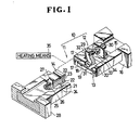
- Figure 1 is a fragmentary perspective view, partly in cross section, of an apparatus embodying the present invention;
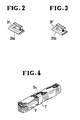
- Figure 2 is a perspective view of a knife blade of the apparatus shown in Figure 1;
- Figure 3 is a perspective view of a modified knife blade;
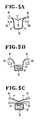
- Figure 4 is a schematic perspective view showing an example of elongate articles bundled together on the apparatus shown in Figure 1;
- Figures 5A through 5C are schematic views showing the sequence of bundling steps according to the present invention;
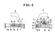
- Figures 6 and 7A through 7C are views illustrating a successive steps of operation of the apparatus shown in Figure 1;
- Figures 8 and 9 are schematic perspective views respectively showing examplified packages produced on the apparatus of Figure 1.
- The present invention is particularly useful when embodied in a package-sealing apparatus such as shown in Figure 1, generally indicated by the
reference numeral 10. - The
apparatus 10 generally comprises a heat-sealing unit 11 and acutting unit 12 associated with one of a pair of horizontally opposedsealing heads sealing unit 11. - The first sealing
head 13 comprises a rectangular plate detachably connected to a front end of afirst slide arm 15 by means of a pair of screws (not designated). Theslide arm 15 is slidably mounted on afirst guide block 16 secured to a non-illustrated frame of theapparatus 10. The sealinghead 13 includes a pair of parallel spacedsealing lands 17 extending horizontally across the face thereof, and an elongate central aperture orchannel 18 defined between thesealing lands 17. Each of the sealinglands 17 has a front surface coated with afilm 19 of fluorine plastics. Theslide arm 15 includes a generally L-shaped recess 20 for purposes described below. Therecess 20 has one end connected with thechannel 18 and the other end opening to an upper surface of theslide arm 15. - The second sealing
head 14 comprises a generally rectangular block of fluorine plastics and is fastened to a front end of apresser block 21 via a dovetail joint. The second sealinghead 14 includes a pair of parallel spacedsealing lands central channel 23 defined between thelands 22. Thepresser block 21 is slidably received in a recessedfront end portion 24 of asecond slide arm 25 and is slidably movable toward and away from the first sealinghead 13 for a limited distance. Acompression coil spring 26 is disposed between and acts between theslide arm 25 and thepresser block 21 to urge the latter and hence the sealinghead 14 toward the first sealinghead 13. Thepresser block 21 has astopper lug 27 disposed on a rear end thereof and projecting upwardly outwardly from therecessed portion 24. Thestopper lug 27 is engageable with theslide arm 25 to limit reciprocating movement of thepresser block 21. Theslide arm 25 is slidably mounted on asecond guide block 28 secured to the frame of theapparatus 10. The first andsecond slide arms - The
cutting unit 12 includes a generally L-shaped cutting knife 29 reciprocably received in therecess 20 in thefirst slide arm 15, and anactuator 30 mounted on theslide arm 15 for reciprocating thecutting knife 29. Thecutting knife 29 includes ahorizontal knife blade 31 movable through thechannel 18 in the sealinghead 13, and avertical stem 32 projecting upwardly outwardly from therecess 20. Theactuator 30 comprises a fluid-actuated cylinder, such as an air cylinder having apiston rod 33 connected to thestem 32 of thecutting knife 29. Thecylinder 30 is supported by abracket 34 secured to theslide arm 15. As shown in Figure 2, theknife blade 31 has a tapered, notchedcutting edge 31a. As an alternative, it is possible to use a knife blade 31' having a tapered,continuous cutting edge 31b, as shown in Figure 3. - At least one of the
sealing heads cutting unit 12 is being actuated to sever the webs. - Preferably, the package-
sealing apparatus 10 thus constructed is incorporated in a packaging or binding machine for fastening together a desired number of elongate articles F by a pair of binding strips or webs T, as shown in Figures 5A - 5C, 6 and 7A - 7C. The binding machine includes a pair of opposed tape feeders A, A disposed above therespective sealing heads apparatus 10 for supplying a pair of continuous binding tapes T' downwardly toward theapparatus 10 across the path of movement of thesealing heads - Operation of the package-sealing
apparatus 10 is described below with reference to Figures 5A - 5C, 6 and 7A - 7C. Theapparatus 10 is operatively connected with the binding machine to move in timed relation to the tape feeders A, A and a non-illustrated fastener feeder of the binding machine. - As shown in Figure 5A, a pair of continuous thermoplastic binding tapes T', T', with their leading ends S fused together, is fed by the respective tape feeders A, A to extend downwardly through the path of movement of the
sealing heads sealing heads - Then a desired number of the fastener tapes F are supplyed from the tape feeder, not shown, onto the U-shaped lengths of the binding tapes T', T', as shown in Figure 5B.
- Thereafter, the
slide arms sealing heads sealing lands respective sealing heads sealing heads lands channels respective sealing heads tension coil spring 26 continuously exerts a back tension or pressure on thepresser block 21 to ensure that the binding tapes T' are brought into mutual sealing engagement with each other by and between the sealinghead 13 and the spring-loadedsealing head 14. Thespring 26 also functions to absorb a shock force applied thereto when theknife blade 31 abuts agaist the sealinghead 14. - While keeping this condition, the
cylinder 30 is actuated to extend itspiston rod 33 whereupon theknife blade 31 is moved to project outwardly from the sealing head through the channel 18 (Figure 7A) into thechannel 23 in the sealinghead 14, thereby severing the binding tapes T' along the non-fused intermediate portion of the overlapping region of the tapes T'. Since theknife blade 31 is thermally isolated from the heatedsealing heads knife blade 31. - Then the
cylinder 30 is actuated to return theknife blade 31 to its initial retracted position, and finally theslide arms plastic films 19 overlying the respectve sealinglands 17 of the sealinghead 13 and the sealinghead 14 molded of fluorine plastics make it posssible to smoothly separate the binding tapes T, T' from the sealingheads - The package-sealing
apparatus 10 of the present invention is also suitable for continuous sealing of packages made on a form and fill packaging machien. In such machine, as shown in Figure 8, a web of thermoplastic packaging film TU is formed into a tubular configuration. The formed tube of packaging film TU has an end seal S made transversely thereacross by theapparatus 10. After product is inserted into the tube TU, another end seal S1 is made and a filed package P is severed by theapparatus 10. At the same time, a leading end seal S for the next package is formed. - Figure 9 shows two open wrapping tubes B, B with one end S closed by the
apparatus 10. For making the tubes B, an empty tubular package, similar to the package P shown in Figure 8, is severed transversely across an intermediate portion thereof.
Claims (12)
Applications Claiming Priority (2)
| Application Number | Priority Date | Filing Date | Title |
|---|---|---|---|
| JP1985165834U JPS6276107U (en) | 1985-10-30 | 1985-10-30 | |
| JP165834/85U | 1985-10-30 |
Publications (3)
| Publication Number | Publication Date |
|---|---|
| EP0233318A2 true EP0233318A2 (en) | 1987-08-26 |
| EP0233318A3 EP0233318A3 (en) | 1987-09-30 |
| EP0233318B1 EP0233318B1 (en) | 1992-02-05 |
Family
ID=15819883
Family Applications (1)
| Application Number | Title | Priority Date | Filing Date |
|---|---|---|---|
| EP86114141A Expired - Lifetime EP0233318B1 (en) | 1985-10-30 | 1986-10-13 | Apparatus for sealing packages |
Country Status (9)
| Country | Link |
|---|---|
| EP (1) | EP0233318B1 (en) |
| JP (1) | JPS6276107U (en) |
| KR (1) | KR930000669Y1 (en) |
| AU (1) | AU570151B2 (en) |
| CA (1) | CA1264157A (en) |
| DE (1) | DE3683840D1 (en) |
| HK (1) | HK95094A (en) |
| MY (1) | MY100252A (en) |
| SG (1) | SG102794G (en) |
Cited By (2)
| Publication number | Priority date | Publication date | Assignee | Title |
|---|---|---|---|---|
| CN116968979A (en) * | 2023-08-31 | 2023-10-31 | 梵思奇(广东)动漫文化有限公司 | A kind of twisted rope hot pressing binding equipment |
| NL2036005B1 (en) * | 2023-10-11 | 2025-04-24 | Buhrs Packaging Solutions B V | Assembly of a product and a packaging wrapped around the product |
Family Cites Families (6)
| Publication number | Priority date | Publication date | Assignee | Title |
|---|---|---|---|---|
| SE351592C (en) * | 1972-03-29 | 1974-05-06 | Iwema Foerpacknings Ab | Welding jaws for welding foil webs together |
| US4512138A (en) * | 1982-03-04 | 1985-04-23 | The Dow Chemical Company | Form, fill and seal machine with hot gas and thermal impulse sealing |
| JPS59199410A (en) * | 1983-04-26 | 1984-11-12 | 大森機械工業株式会社 | Bundling device for paper sheets stacked at every arbitray number |
| JPS6045118A (en) * | 1983-08-11 | 1985-03-11 | ワイケイケイ株式会社 | Method and device for banding long-sized product |
| US4537012A (en) * | 1983-10-28 | 1985-08-27 | Package Machinery Company | Packaging machine with rotary actuated sealing jaws |
| JPS6239426A (en) * | 1985-08-15 | 1987-02-20 | オリヒロ株式会社 | Bagging lateral sealing mechanism |
-
1985
- 1985-10-30 JP JP1985165834U patent/JPS6276107U/ja active Pending
-
1986
- 1986-10-13 DE DE8686114141T patent/DE3683840D1/en not_active Expired - Lifetime
- 1986-10-13 EP EP86114141A patent/EP0233318B1/en not_active Expired - Lifetime
- 1986-10-16 AU AU64107/86A patent/AU570151B2/en not_active Ceased
- 1986-10-20 CA CA000520850A patent/CA1264157A/en not_active Expired - Lifetime
- 1986-10-24 KR KR2019860016217U patent/KR930000669Y1/en not_active Expired - Fee Related
- 1986-10-29 MY MYPI86000051A patent/MY100252A/en unknown
-
1994
- 1994-07-26 SG SG102794A patent/SG102794G/en unknown
- 1994-09-08 HK HK95094A patent/HK95094A/en unknown
Cited By (3)
| Publication number | Priority date | Publication date | Assignee | Title |
|---|---|---|---|---|
| CN116968979A (en) * | 2023-08-31 | 2023-10-31 | 梵思奇(广东)动漫文化有限公司 | A kind of twisted rope hot pressing binding equipment |
| NL2036005B1 (en) * | 2023-10-11 | 2025-04-24 | Buhrs Packaging Solutions B V | Assembly of a product and a packaging wrapped around the product |
| WO2025080136A3 (en) * | 2023-10-11 | 2025-05-22 | Buhrs Packaging Solutions B.V. | Assembly of a product and a packaging wrapped around the product, related method of forming and sealing station |
Also Published As
| Publication number | Publication date |
|---|---|
| MY100252A (en) | 1990-07-28 |
| JPS6276107U (en) | 1987-05-15 |
| DE3683840D1 (en) | 1992-03-19 |
| SG102794G (en) | 1994-10-28 |
| CA1264157A (en) | 1990-01-02 |
| EP0233318B1 (en) | 1992-02-05 |
| EP0233318A3 (en) | 1987-09-30 |
| AU6410786A (en) | 1987-05-28 |
| KR870006724U (en) | 1987-05-09 |
| AU570151B2 (en) | 1988-03-03 |
| KR930000669Y1 (en) | 1993-02-19 |
| HK95094A (en) | 1994-09-16 |
Similar Documents
| Publication | Publication Date | Title |
|---|---|---|
| AU713121B2 (en) | Reclosable storage bag | |
| US6350057B1 (en) | Reinforced reclosable package seals | |
| EP0481783B1 (en) | Method and apparatus for forming a reclosable package | |
| CA2125204C (en) | Vertical-type filling and packaging machine | |
| US4410089A (en) | Flexible package, and method and apparatus for manufacturing same | |
| US7325370B2 (en) | Machine to make E-Z open pouch with flap and bulge | |
| US20050008266A1 (en) | Reclosable package having internal seal made of double-sided adhesive tape | |
| US5276950A (en) | Closure strips for bags | |
| US4823945A (en) | Protective cushioning | |
| KR100301420B1 (en) | How to arrange the zipper strip and the zipper strip laterally about the longitudinal axis | |
| EP0233318B1 (en) | Apparatus for sealing packages | |
| JP5000892B2 (en) | Method for manufacturing reclosable package with slider-operated string zipper | |
| US3956045A (en) | Method and apparatus for bonding layers of resinous material | |
| JP2003001729A (en) | Method and apparatus for forming re-closable package and package produced by the method | |
| JP2512784B2 (en) | Packaging method and packaging device | |
| GB2243135A (en) | Bag tying machine | |
| US3264794A (en) | Packaging apparatus | |
| JP3445211B2 (en) | Packaging material roll | |
| EP1010653B1 (en) | Tape splicing device | |
| GB2048764A (en) | Apparatus for adhering rider strips to the flattened end edges of tube sections or sacks | |
| MX2008009851A (en) | Easy-tear, non-laminated, polyolefin based pouch and method of fabrication. | |
| JP2517835B2 (en) | Automatic packaging machine | |
| WO1999058323A1 (en) | Method and apparatus for production of bags | |
| CA2040587A1 (en) | Apparatus for heat-sealing a thermoplastic packaging bag | |
| JP2684018B2 (en) | Packaging equipment using a cylindrical net made of synthetic resin |
Legal Events
| Date | Code | Title | Description |
|---|---|---|---|
| PUAI | Public reference made under article 153(3) epc to a published international application that has entered the european phase |
Free format text: ORIGINAL CODE: 0009012 |
|
| PUAL | Search report despatched |
Free format text: ORIGINAL CODE: 0009013 |
|
| AK | Designated contracting states |
Kind code of ref document: A2 Designated state(s): DE FR GB IT |
|
| AK | Designated contracting states |
Kind code of ref document: A3 Designated state(s): DE FR GB IT |
|
| 17P | Request for examination filed |
Effective date: 19871216 |
|
| 17Q | First examination report despatched |
Effective date: 19881206 |
|
| ITTA | It: last paid annual fee | ||
| GRAA | (expected) grant |
Free format text: ORIGINAL CODE: 0009210 |
|
| AK | Designated contracting states |
Kind code of ref document: B1 Designated state(s): DE FR GB IT |
|
| ITF | It: translation for a ep patent filed | ||
| REF | Corresponds to: |
Ref document number: 3683840 Country of ref document: DE Date of ref document: 19920319 |
|
| ET | Fr: translation filed | ||
| PGFP | Annual fee paid to national office [announced via postgrant information from national office to epo] |
Ref country code: LU Payment date: 19920619 Year of fee payment: 7 |
|
| EPTA | Lu: last paid annual fee | ||
| PLBE | No opposition filed within time limit |
Free format text: ORIGINAL CODE: 0009261 |
|
| STAA | Information on the status of an ep patent application or granted ep patent |
Free format text: STATUS: NO OPPOSITION FILED WITHIN TIME LIMIT |
|
| 26N | No opposition filed | ||
| PGFP | Annual fee paid to national office [announced via postgrant information from national office to epo] |
Ref country code: FR Payment date: 19940923 Year of fee payment: 9 |
|
| PGFP | Annual fee paid to national office [announced via postgrant information from national office to epo] |
Ref country code: GB Payment date: 19941004 Year of fee payment: 9 |
|
| PGFP | Annual fee paid to national office [announced via postgrant information from national office to epo] |
Ref country code: DE Payment date: 19941031 Year of fee payment: 9 |
|
| ITPR | It: changes in ownership of a european patent |
Owner name: CAMBIO RAGIONE SOCIALE;YKK CORPORATION |
|
| REG | Reference to a national code |
Ref country code: FR Ref legal event code: CD |
|
| PG25 | Lapsed in a contracting state [announced via postgrant information from national office to epo] |
Ref country code: GB Effective date: 19951013 |
|
| GBPC | Gb: european patent ceased through non-payment of renewal fee |
Effective date: 19951013 |
|
| PG25 | Lapsed in a contracting state [announced via postgrant information from national office to epo] |
Ref country code: FR Effective date: 19960628 |
|
| PG25 | Lapsed in a contracting state [announced via postgrant information from national office to epo] |
Ref country code: DE Effective date: 19960702 |
|
| REG | Reference to a national code |
Ref country code: FR Ref legal event code: ST |
|
| PG25 | Lapsed in a contracting state [announced via postgrant information from national office to epo] |
Ref country code: IT Free format text: LAPSE BECAUSE OF NON-PAYMENT OF DUE FEES;WARNING: LAPSES OF ITALIAN PATENTS WITH EFFECTIVE DATE BEFORE 2007 MAY HAVE OCCURRED AT ANY TIME BEFORE 2007. THE CORRECT EFFECTIVE DATE MAY BE DIFFERENT FROM THE ONE RECORDED. Effective date: 20051013 |