EP0233303B1 - Planetary gear apparatus - Google Patents
Planetary gear apparatus Download PDFInfo
- Publication number
- EP0233303B1 EP0233303B1 EP86102141A EP86102141A EP0233303B1 EP 0233303 B1 EP0233303 B1 EP 0233303B1 EP 86102141 A EP86102141 A EP 86102141A EP 86102141 A EP86102141 A EP 86102141A EP 0233303 B1 EP0233303 B1 EP 0233303B1
- Authority
- EP
- European Patent Office
- Prior art keywords
- input shaft
- external gear
- output shaft
- shaft
- gear
- Prior art date
- Legal status (The legal status is an assumption and is not a legal conclusion. Google has not performed a legal analysis and makes no representation as to the accuracy of the status listed.)
- Expired - Lifetime
Links
- 230000005540 biological transmission Effects 0.000 description 3
- 238000003754 machining Methods 0.000 description 3
- 230000002411 adverse Effects 0.000 description 1
- 230000004323 axial length Effects 0.000 description 1
- 239000003638 chemical reducing agent Substances 0.000 description 1
- 238000010276 construction Methods 0.000 description 1
- 230000000694 effects Effects 0.000 description 1
- 230000010355 oscillation Effects 0.000 description 1
Images

Classifications
-
- F—MECHANICAL ENGINEERING; LIGHTING; HEATING; WEAPONS; BLASTING
- F16—ENGINEERING ELEMENTS AND UNITS; GENERAL MEASURES FOR PRODUCING AND MAINTAINING EFFECTIVE FUNCTIONING OF MACHINES OR INSTALLATIONS; THERMAL INSULATION IN GENERAL
- F16H—GEARING
- F16H1/00—Toothed gearings for conveying rotary motion
- F16H1/28—Toothed gearings for conveying rotary motion with gears having orbital motion
- F16H1/32—Toothed gearings for conveying rotary motion with gears having orbital motion in which the central axis of the gearing lies inside the periphery of an orbital gear
-
- F—MECHANICAL ENGINEERING; LIGHTING; HEATING; WEAPONS; BLASTING
- F16—ENGINEERING ELEMENTS AND UNITS; GENERAL MEASURES FOR PRODUCING AND MAINTAINING EFFECTIVE FUNCTIONING OF MACHINES OR INSTALLATIONS; THERMAL INSULATION IN GENERAL
- F16H—GEARING
- F16H1/00—Toothed gearings for conveying rotary motion
- F16H1/28—Toothed gearings for conveying rotary motion with gears having orbital motion
- F16H2001/2881—Toothed gearings for conveying rotary motion with gears having orbital motion comprising two axially spaced central gears, i.e. ring or sun gear, engaged by at least one common orbital gear wherein one of the central gears is forming the output
-
- F—MECHANICAL ENGINEERING; LIGHTING; HEATING; WEAPONS; BLASTING
- F16—ENGINEERING ELEMENTS AND UNITS; GENERAL MEASURES FOR PRODUCING AND MAINTAINING EFFECTIVE FUNCTIONING OF MACHINES OR INSTALLATIONS; THERMAL INSULATION IN GENERAL
- F16H—GEARING
- F16H1/00—Toothed gearings for conveying rotary motion
- F16H1/28—Toothed gearings for conveying rotary motion with gears having orbital motion
- F16H1/32—Toothed gearings for conveying rotary motion with gears having orbital motion in which the central axis of the gearing lies inside the periphery of an orbital gear
- F16H2001/322—Toothed gearings for conveying rotary motion with gears having orbital motion in which the central axis of the gearing lies inside the periphery of an orbital gear comprising at least one universal joint or flexible coupling, e.g. a Cardan joint
Definitions
- the invention relates to a planetary gear apparatus of the kind defined by the precharacterizing features of claim 1.
- a typical conventional planetary gear apparatus is known from the EP-A-114 561.
- the power transmission mechanism of this known apparatus applies a radial force to the output shaft. It is therefore necessary to provide a flange which is rigid enough to prevent the output shaft from being deformed by the application of that radial force. For that reason, the size of the portions of the transmission mechanism near the output shaft cannot be reduced in diametrical direction of the output shaft, which impedes any reduction in the size of the apparatus as a whole. Further, said mechanism requires highly-accurate machining and must also have a suitably high rigidity, since any slight deformation of a portion thereof has an adverse effect on the operation.
- a planetary gear apparatus of the kind defined at the preamble is known from the FR-A-2 247 647.
- the input shaft of this known apparatus is supported in a cantilever fashion, thus requiring to increase the size of the input shaft and the bearing thereof so that it is not possible to provide a compact apparatus.
- an input shaft 21 is formed with an eccentric member 22.
- An external gear 24 is fitted on the eccentric member 22 through a bearing 23. Accordingly, the external gear 24 is disposed in S uGh a manner that the axis of the external sear 24 is eccentric with respect to the axis of the input shaft 21 (and also an internal gear 26).
- Outer teeth 25 of the external gear 24 have an appropriate tooth form such as a trochoidal or circular tooth form.
- the outer teeth 25 engage with inner teeth of the internal gear 26 which are constituted by inner pins 27.
- An annular groove 42 is provided on the side of the external gear 24 which is closer to an output shaft 30.
- the annular groove 42 is provided with inner splines 43 which are concentric with respect to the external gear 24.
- the recess 31 of the output shaft 30 is provided on the outer side thereof with outer splines 44 which are concentric with respect to the input shaft 21.
- a floating drive 47 which has outer and inner splines 45 and 46 is floating between the inner and outer splines 43 and 44.
- the drive 47 is constituted by a hollow shaft having a through-hole defined therein.
- the input shaft 21 is received through the through-hole and is rotatably supported by a bearing 37 within the recess 31 of the output shaft 30. Accordingly, the input shaft 21 is supported at two portions on both sides of the external gear 24 by the bearing 37 and 38, respectively.
- the internal gear 26 is tubular and integral with an outer-shaft casing and is secured to an input-shaft casing 39 by bolts 40.
- the output shaft 30 is rotatably supported by the output-shaft casing integral with the integral gear 26 through bearing 41.
- the eccentric member 22 As the input shaft 21 rotates, the eccentric member 22 also rotates, so that a rotational force imparted from the input shaft 21 is transmitted to the external gear 24 through the bearing 23. Since the axis of the input shaft 21 and the axis of rotation of the external gear 24 are eccentric with respect to each other and the external gear 24 is operatively connected to the floating drive 47 through the annular groove 42, the revolution of the external gear 24 around the axis of the input shaft 21 is absorbed by the oscillation of the drive 47, and the rotational force from the input shaft 21 alone is taken out after its rotational speed has been reduced to the reciprocal of number of outer teeth 25 because of the engagement between the external gear 24 and the outer pin 27. The rotational motion of the external gear 24 is transmitted to the drive 47 through the annular groove 42 and is further transmitted to the output shaft 30.
- the load which acts on the input shaft 21 is applied thereto through the external gear 24.
- the input shaft 21 is supported at two portions on both sides of the external gear 24 by the bearings 37 and 38, respectively, a correspondingly reduced load is applied to each of the bearings 37 and 38, and this means that it is possible to reduce the size of the bearings 37 and 38.
- the present invention which is arranged and operates as described above, offers the following various advantages.
- the drive which is constituted by a hollow shaft enables a reduction in weight of the apparatus as a whole.
- the present invention needs no inner roller bores. Therefore, the diameter in the radial direction of the external gear can be minimized, so that it is possible to obtain a reduction gear apparatus with a reduced size.
- the internal gear which is tubular and integral with the output-shaft casing enables the output- side of the apparatus to have a reduced size and a simplified structure and permits transmission of large torque, since there is no connection by means of a bolt.
Landscapes
- Engineering & Computer Science (AREA)
- General Engineering & Computer Science (AREA)
- Mechanical Engineering (AREA)
- Retarders (AREA)
Description
- The invention relates to a planetary gear apparatus of the kind defined by the precharacterizing features of claim 1.
- A typical conventional planetary gear apparatus is known from the EP-A-114 561. The power transmission mechanism of this known apparatus applies a radial force to the output shaft. It is therefore necessary to provide a flange which is rigid enough to prevent the output shaft from being deformed by the application of that radial force. For that reason, the size of the portions of the transmission mechanism near the output shaft cannot be reduced in diametrical direction of the output shaft, which impedes any reduction in the size of the apparatus as a whole. Further, said mechanism requires highly-accurate machining and must also have a suitably high rigidity, since any slight deformation of a portion thereof has an adverse effect on the operation.
- A planetary gear apparatus of the kind defined at the preamble is known from the FR-A-2 247 647. The input shaft of this known apparatus, however, is supported in a cantilever fashion, thus requiring to increase the size of the input shaft and the bearing thereof so that it is not possible to provide a compact apparatus.
- In the DE-A-2 358 827 a similar planetary gear apparatus is shown, with the reaction and output changed, wherein the input shaft has a bearing in a recess of the output shaft. The inner gear of this known apparatus, however, is arranged to rotate and the rotation of said inner gear is differently transmitted to the output shaft so that the construction of this apparatus is generally complicated and fails to provide compactness.
- It is therefore the object of the present invention to provide a planetary gear apparatus of the kind defined at the preamble which has a simple mechanism which enables the input-shaft side of the apparatus to have a simplified structure and a reduced size, the apparatus further having a reduced axial length and an output-shaft side which also has simplified structure and reduced size.
- This object is attained by the characterizing features of the claim 1. Advantageous embodiments of the invention are defined by subclaim 2.
- The advantages of the present invention will become more apparent from the following description of a preferred embodiment thereof, taken in conjunction with the accompanying drawing, wherein
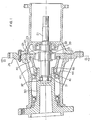
- Fig. 1 is a sectional view of an embodiment of the present invention, and
- Fig. 2 is a sectional view taken along the line B-B of Fig. 1.
- Referring to Figs. 1 and 2 which show in combination an embodiment of the present invention, an
input shaft 21 is formed with aneccentric member 22. Anexternal gear 24 is fitted on theeccentric member 22 through abearing 23. Accordingly, theexternal gear 24 is disposed in SuGh a manner that the axis of theexternal sear 24 is eccentric with respect to the axis of the input shaft 21 (and also an internal gear 26).Outer teeth 25 of theexternal gear 24 have an appropriate tooth form such as a trochoidal or circular tooth form. Theouter teeth 25 engage with inner teeth of theinternal gear 26 which are constituted byinner pins 27. - An
annular groove 42 is provided on the side of theexternal gear 24 which is closer to anoutput shaft 30. Theannular groove 42 is provided withinner splines 43 which are concentric with respect to theexternal gear 24. On the other hand, therecess 31 of theoutput shaft 30 is provided on the outer side thereof withouter splines 44 which are concentric with respect to theinput shaft 21. In addition, afloating drive 47 which has outer andinner splines outer splines - The
drive 47 is constituted by a hollow shaft having a through-hole defined therein. Theinput shaft 21 is received through the through-hole and is rotatably supported by abearing 37 within therecess 31 of theoutput shaft 30. Accordingly, theinput shaft 21 is supported at two portions on both sides of theexternal gear 24 by thebearing - The
internal gear 26 is tubular and integral with an outer-shaft casing and is secured to an input-shaft casing 39 by bolts 40. Theoutput shaft 30 is rotatably supported by the output-shaft casing integral with theintegral gear 26 through bearing 41. - The following is a description of the operation of the planetary gear apparatus according to the present invention, arranged as described above.
- As the
input shaft 21 rotates, theeccentric member 22 also rotates, so that a rotational force imparted from theinput shaft 21 is transmitted to theexternal gear 24 through thebearing 23. Since the axis of theinput shaft 21 and the axis of rotation of theexternal gear 24 are eccentric with respect to each other and theexternal gear 24 is operatively connected to thefloating drive 47 through theannular groove 42, the revolution of theexternal gear 24 around the axis of theinput shaft 21 is absorbed by the oscillation of thedrive 47, and the rotational force from theinput shaft 21 alone is taken out after its rotational speed has been reduced to the reciprocal of number ofouter teeth 25 because of the engagement between theexternal gear 24 and theouter pin 27. The rotational motion of theexternal gear 24 is transmitted to thedrive 47 through theannular groove 42 and is further transmitted to theoutput shaft 30. - The load which acts on the
input shaft 21 is applied thereto through theexternal gear 24. However, since theinput shaft 21 is supported at two portions on both sides of theexternal gear 24 by thebearings bearings bearings - Although the present invention has been described above with respect to a gear reducer, it is to be noted here that the invention may also be applied to a speed increaser.
- The present invention, which is arranged and operates as described above, offers the following various advantages.
- Since the input shaft is supported at two portions on both sides of the external gear, it is possible to reduce the size of the bearings which rotatably support the input shaft, so that each of the input shaft and the input-shaft casing is allowed to have a reduced size and a simplified structure.
- The drive which is constituted by a hollow shaft enables a reduction in weight of the apparatus as a whole.
- Since the drive is supported in such a manner that it floats with respect to the carrier or the annular groove of the external gear and the output shaft, any possible machining error can be absorbed, so that there is no need for a specially high degree of accuracy in machining.
- The present invention needs no inner roller bores. Therefore, the diameter in the radial direction of the external gear can be minimized, so that it is possible to obtain a reduction gear apparatus with a reduced size.
- Since torque alone is transmitted to the output shaft and no radial load acts thereon, it is possible to reduce any angular back-lash which may be generated as a result of deformation of the output shaft.
- The internal gear which is tubular and integral with the output-shaft casing enables the output- side of the apparatus to have a reduced size and a simplified structure and permits transmission of large torque, since there is no connection by means of a bolt.
Claims (2)
Priority Applications (3)
| Application Number | Priority Date | Filing Date | Title |
|---|---|---|---|
| EP86102141A EP0233303B1 (en) | 1986-02-19 | 1986-02-19 | Planetary gear apparatus |
| DE8686102141T DE3675009D1 (en) | 1986-02-19 | 1986-02-19 | PLANETARY GEARBOX. |
| US07/083,901 US4770062A (en) | 1986-02-19 | 1987-08-06 | Planetary gear apparatus |
Applications Claiming Priority (1)
| Application Number | Priority Date | Filing Date | Title |
|---|---|---|---|
| EP86102141A EP0233303B1 (en) | 1986-02-19 | 1986-02-19 | Planetary gear apparatus |
Publications (2)
| Publication Number | Publication Date |
|---|---|
| EP0233303A1 EP0233303A1 (en) | 1987-08-26 |
| EP0233303B1 true EP0233303B1 (en) | 1990-10-17 |
Family
ID=8194905
Family Applications (1)
| Application Number | Title | Priority Date | Filing Date |
|---|---|---|---|
| EP86102141A Expired - Lifetime EP0233303B1 (en) | 1986-02-19 | 1986-02-19 | Planetary gear apparatus |
Country Status (3)
| Country | Link |
|---|---|
| US (1) | US4770062A (en) |
| EP (1) | EP0233303B1 (en) |
| DE (1) | DE3675009D1 (en) |
Families Citing this family (14)
| Publication number | Priority date | Publication date | Assignee | Title |
|---|---|---|---|---|
| JPH0627532B2 (en) * | 1987-04-13 | 1994-04-13 | 住友重機械工業株式会社 | Planetary gearbox |
| JPH01312250A (en) * | 1988-02-05 | 1989-12-18 | Sumitomo Heavy Ind Ltd | Differential gear mechanism using planetary gear speed reducer of internal engagement type |
| JP2743292B2 (en) * | 1990-10-17 | 1998-04-22 | 住友重機械工業株式会社 | Rotary drive with internal gear planetary gear reducer with freewheel mechanism |
| SE9402701L (en) * | 1994-08-12 | 1995-09-18 | Gustav Rennerfelt | eccentric |
| US5743348A (en) * | 1995-02-13 | 1998-04-28 | New Venture Gear, Inc. | Single speed transmission for an electric motor vehicle |
| US5954737A (en) * | 1997-12-19 | 1999-09-21 | Neurovasx, Inc. | Thrombus macerator catheter |
| JP2006015856A (en) * | 2004-07-01 | 2006-01-19 | Toyoda Mach Works Ltd | Variable transmission ratio steering device |
| US9017381B2 (en) | 2007-04-10 | 2015-04-28 | Biomet Sports Medicine, Llc | Adjustable knotless loops |
| DE102006023535B4 (en) * | 2006-05-19 | 2008-12-18 | Keiper Gmbh & Co.Kg | Gear stage for an actuator |
| JP2012197874A (en) * | 2011-03-22 | 2012-10-18 | Seiko Epson Corp | Reduction gear |
| JP2012197875A (en) | 2011-03-22 | 2012-10-18 | Seiko Epson Corp | Speed reducer |
| EP2980447A1 (en) * | 2014-07-28 | 2016-02-03 | Siemens Aktiengesellschaft | Eccentric gear assembly or eccentric stage and drive with eccentric drive or eccentric stage |
| US10039543B2 (en) | 2014-08-22 | 2018-08-07 | Biomet Sports Medicine, Llc | Non-sliding soft anchor |
| CN108087500A (en) * | 2017-12-22 | 2018-05-29 | 王海清 | Tapered roller cycloid drive mechanism |
Citations (2)
| Publication number | Priority date | Publication date | Assignee | Title |
|---|---|---|---|---|
| EP0108841A1 (en) * | 1982-11-04 | 1984-05-23 | Curtis, Lloyd Stuart | Improved hypocyclic drive transmission apparatus |
| EP0114561A1 (en) * | 1982-12-27 | 1984-08-01 | Emerson Electric Co. | Motion transmitting system |
Family Cites Families (18)
| Publication number | Priority date | Publication date | Assignee | Title |
|---|---|---|---|---|
| US2381215A (en) * | 1942-01-12 | 1945-08-07 | Ind Res Lab Ltd | Burner control apparatus |
| GB587607A (en) * | 1944-11-17 | 1947-04-30 | Sidney David Lancaster | Improvements in or relating to electric motors with speed reduction gearing |
| US3144791A (en) * | 1958-06-06 | 1964-08-18 | Aubry H Temple | Speed reducer |
| US3073184A (en) * | 1960-05-10 | 1963-01-15 | Brarern Rudolf | Planetary gear |
| US3146638A (en) * | 1960-10-19 | 1964-09-01 | Renault | Rotary engine transmission systems |
| US3252356A (en) * | 1963-05-10 | 1966-05-24 | Kelsey Hayes Co | Gear reduction unit |
| FR1535643A (en) * | 1967-06-19 | 1968-08-09 | Improvements in speed reducers | |
| DE2351040A1 (en) * | 1973-10-11 | 1975-04-17 | Hoesch Werke Ag | ECCENTRIC REVERSING GEAR |
| DE2358827C2 (en) * | 1973-11-26 | 1975-10-02 | Fa. R. Stahl, 7000 Stuttgart | Gear arrangement with a drive motor |
| DE2433675C3 (en) * | 1974-07-12 | 1981-07-23 | Braren, Rudolf, 8000 München | Planetary gear with eccentric and cyclic teeth |
| CA1031983A (en) * | 1977-02-16 | 1978-05-30 | Cyril J. Astill | Sealed torque transmission assembly |
| DE2830909A1 (en) * | 1978-07-13 | 1980-01-31 | Schlatter Ag | DRIVING DEVICE FOR THE ROTATING CAROUSEL IN AN INDUSTRIAL ROBOT |
| US4429595A (en) * | 1980-10-23 | 1984-02-07 | Emerson Electric Co. | Motion transmitting device |
| US4567790A (en) * | 1981-11-18 | 1986-02-04 | Emerson Electric Company | Motion transmitting system |
| JPS60146939A (en) * | 1983-12-31 | 1985-08-02 | Sumitomo Heavy Ind Ltd | Planetary gear-type speed multiply and reduction gear |
| JPS6138242A (en) * | 1984-07-31 | 1986-02-24 | Sumitomo Heavy Ind Ltd | Accelerating/decelerating device of planetary gear |
| JPH113340A (en) * | 1997-06-12 | 1999-01-06 | Mitsubishi Electric Corp | Manufacturing history search device |
| JPH117940A (en) * | 1997-06-13 | 1999-01-12 | Aiwa Co Ltd | Battery improper installation detection circuit |
-
1986
- 1986-02-19 DE DE8686102141T patent/DE3675009D1/en not_active Expired - Fee Related
- 1986-02-19 EP EP86102141A patent/EP0233303B1/en not_active Expired - Lifetime
-
1987
- 1987-08-06 US US07/083,901 patent/US4770062A/en not_active Expired - Lifetime
Patent Citations (2)
| Publication number | Priority date | Publication date | Assignee | Title |
|---|---|---|---|---|
| EP0108841A1 (en) * | 1982-11-04 | 1984-05-23 | Curtis, Lloyd Stuart | Improved hypocyclic drive transmission apparatus |
| EP0114561A1 (en) * | 1982-12-27 | 1984-08-01 | Emerson Electric Co. | Motion transmitting system |
Also Published As
| Publication number | Publication date |
|---|---|
| US4770062A (en) | 1988-09-13 |
| DE3675009D1 (en) | 1990-11-22 |
| EP0233303A1 (en) | 1987-08-26 |
Similar Documents
| Publication | Publication Date | Title |
|---|---|---|
| EP0474897B1 (en) | Planetary speed changing device | |
| US4840090A (en) | Harmonic speed changer | |
| US5324240A (en) | Eccentric gear system | |
| US4407170A (en) | Speed change device | |
| US4391163A (en) | Planetary gear assembly | |
| US4665771A (en) | Hypocyclic drive | |
| US6261199B1 (en) | Non-back drive power transmission | |
| US4760759A (en) | Geared ratio coupling | |
| US5697868A (en) | Planetary speed reduction gear | |
| US4770062A (en) | Planetary gear apparatus | |
| EP0287037B1 (en) | Planetary gear apparatus | |
| EP4276331A1 (en) | Nutation gear reducer | |
| JPH11508675A (en) | Compact gear transmission with large gear ratio | |
| JPS591895B2 (en) | Decelerator | |
| JPH05256340A (en) | Structure of inscribed planetary gear | |
| JPS5917066A (en) | Lubricative supporting device for outer pin of rotation converting mechanism | |
| JPH0570013B2 (en) | ||
| KR20220039645A (en) | reducer | |
| US4537094A (en) | Gear transmission | |
| CN217271680U (en) | Duplex gear transmission mechanism | |
| JP2976438B2 (en) | Planetary gear set | |
| EP0098682A1 (en) | Planetary rotation machine | |
| KR100339845B1 (en) | Decelerator | |
| JP2743285B2 (en) | Planetary gear speed reducer | |
| JPS6138242A (en) | Accelerating/decelerating device of planetary gear |
Legal Events
| Date | Code | Title | Description |
|---|---|---|---|
| PUAI | Public reference made under article 153(3) epc to a published international application that has entered the european phase |
Free format text: ORIGINAL CODE: 0009012 |
|
| AK | Designated contracting states |
Kind code of ref document: A1 Designated state(s): AT BE CH DE FR GB IT LI LU NL SE |
|
| 17P | Request for examination filed |
Effective date: 19871216 |
|
| 17Q | First examination report despatched |
Effective date: 19890123 |
|
| GRAA | (expected) grant |
Free format text: ORIGINAL CODE: 0009210 |
|
| AK | Designated contracting states |
Kind code of ref document: B1 Designated state(s): BE DE FR GB IT |
|
| ITF | It: translation for a ep patent filed | ||
| REF | Corresponds to: |
Ref document number: 3675009 Country of ref document: DE Date of ref document: 19901122 |
|
| ET | Fr: translation filed | ||
| PLBE | No opposition filed within time limit |
Free format text: ORIGINAL CODE: 0009261 |
|
| STAA | Information on the status of an ep patent application or granted ep patent |
Free format text: STATUS: NO OPPOSITION FILED WITHIN TIME LIMIT |
|
| 26N | No opposition filed | ||
| ITTA | It: last paid annual fee | ||
| PGFP | Annual fee paid to national office [announced via postgrant information from national office to epo] |
Ref country code: BE Payment date: 19941222 Year of fee payment: 10 |
|
| PGFP | Annual fee paid to national office [announced via postgrant information from national office to epo] |
Ref country code: FR Payment date: 19950227 Year of fee payment: 10 |
|
| PG25 | Lapsed in a contracting state [announced via postgrant information from national office to epo] |
Ref country code: BE Effective date: 19960228 |
|
| BERE | Be: lapsed |
Owner name: SUMITOMO HEAVY INDUSTRIES LTD Effective date: 19960228 |
|
| PG25 | Lapsed in a contracting state [announced via postgrant information from national office to epo] |
Ref country code: FR Effective date: 19961031 |
|
| REG | Reference to a national code |
Ref country code: FR Ref legal event code: ST |
|
| PGFP | Annual fee paid to national office [announced via postgrant information from national office to epo] |
Ref country code: DE Payment date: 20010212 Year of fee payment: 16 |
|
| REG | Reference to a national code |
Ref country code: GB Ref legal event code: IF02 |
|
| PG25 | Lapsed in a contracting state [announced via postgrant information from national office to epo] |
Ref country code: DE Free format text: LAPSE BECAUSE OF NON-PAYMENT OF DUE FEES Effective date: 20020903 |
|
| PGFP | Annual fee paid to national office [announced via postgrant information from national office to epo] |
Ref country code: GB Payment date: 20040218 Year of fee payment: 19 |
|
| PG25 | Lapsed in a contracting state [announced via postgrant information from national office to epo] |
Ref country code: IT Free format text: LAPSE BECAUSE OF NON-PAYMENT OF DUE FEES;WARNING: LAPSES OF ITALIAN PATENTS WITH EFFECTIVE DATE BEFORE 2007 MAY HAVE OCCURRED AT ANY TIME BEFORE 2007. THE CORRECT EFFECTIVE DATE MAY BE DIFFERENT FROM THE ONE RECORDED. Effective date: 20050219 Ref country code: GB Free format text: LAPSE BECAUSE OF NON-PAYMENT OF DUE FEES Effective date: 20050219 |
|
| GBPC | Gb: european patent ceased through non-payment of renewal fee |
Effective date: 20050219 |