EP0233024B1 - Apparatus for detecting micro-organisms - Google Patents
Apparatus for detecting micro-organisms Download PDFInfo
- Publication number
- EP0233024B1 EP0233024B1 EP87300811A EP87300811A EP0233024B1 EP 0233024 B1 EP0233024 B1 EP 0233024B1 EP 87300811 A EP87300811 A EP 87300811A EP 87300811 A EP87300811 A EP 87300811A EP 0233024 B1 EP0233024 B1 EP 0233024B1
- Authority
- EP
- European Patent Office
- Prior art keywords
- container
- station
- rack
- upper support
- containers
- Prior art date
- Legal status (The legal status is an assumption and is not a legal conclusion. Google has not performed a legal analysis and makes no representation as to the accuracy of the status listed.)
- Expired - Lifetime
Links
Images

Classifications
-
- C—CHEMISTRY; METALLURGY
- C12—BIOCHEMISTRY; BEER; SPIRITS; WINE; VINEGAR; MICROBIOLOGY; ENZYMOLOGY; MUTATION OR GENETIC ENGINEERING
- C12M—APPARATUS FOR ENZYMOLOGY OR MICROBIOLOGY; APPARATUS FOR CULTURING MICROORGANISMS FOR PRODUCING BIOMASS, FOR GROWING CELLS OR FOR OBTAINING FERMENTATION OR METABOLIC PRODUCTS, i.e. BIOREACTORS OR FERMENTERS
- C12M41/00—Means for regulation, monitoring, measurement or control, e.g. flow regulation
- C12M41/30—Means for regulation, monitoring, measurement or control, e.g. flow regulation of concentration
- C12M41/36—Means for regulation, monitoring, measurement or control, e.g. flow regulation of concentration of biomass, e.g. colony counters or by turbidity measurements
-
- G—PHYSICS
- G01—MEASURING; TESTING
- G01N—INVESTIGATING OR ANALYSING MATERIALS BY DETERMINING THEIR CHEMICAL OR PHYSICAL PROPERTIES
- G01N33/00—Investigating or analysing materials by specific methods not covered by groups G01N1/00 - G01N31/00
- G01N33/48—Biological material, e.g. blood, urine; Haemocytometers
- G01N33/483—Physical analysis of biological material
- G01N33/487—Physical analysis of biological material of liquid biological material
- G01N33/49—Blood
-
- Y—GENERAL TAGGING OF NEW TECHNOLOGICAL DEVELOPMENTS; GENERAL TAGGING OF CROSS-SECTIONAL TECHNOLOGIES SPANNING OVER SEVERAL SECTIONS OF THE IPC; TECHNICAL SUBJECTS COVERED BY FORMER USPC CROSS-REFERENCE ART COLLECTIONS [XRACs] AND DIGESTS
- Y10—TECHNICAL SUBJECTS COVERED BY FORMER USPC
- Y10S—TECHNICAL SUBJECTS COVERED BY FORMER USPC CROSS-REFERENCE ART COLLECTIONS [XRACs] AND DIGESTS
- Y10S435/00—Chemistry: molecular biology and microbiology
- Y10S435/809—Incubators or racks or holders for culture plates or containers
Definitions
- the present invention relates to apparatus for use in detecting micro-organisms in samples of a substance and can be used, for example, for monitoring substances intended for human consumption, such as foods, drinks or pharmaceuticals, or may be used to monitor pathological samples, such as blood, in the laboratory.
- Blood culturing techniques currently used in hospitals include a method in which a sample of blood is cultured in nutrient broth, from which samples are sub-cultured on agar plates at regular intervals. Not only is this method extremely slow with results not being expected for several days, but it is highly labour intensive and requires good aseptic conditions to be maintained throughout.
- a quicker technique uses a machine sold under the trade name Bactec. To use this machine, the sample is exposed to a radioactive substrate which is consumed by the micro-organisms, which then give off radioactive carbon dioxide for detection by the machine. Although this machine gives results in hours, rather than days, hospital personnel may be concerned by possible radioactive exposure and waste disposal.
- Electrochemical methods have been proposed which include measuring conductance, impedance or potential difference changes, but known apparatus using these methods is not readily susceptible to hospital use in that the sample bottles are kept at a controlled temperature in a water bath which may become contaminated by spillage.
- sample-holding bottles instead of sample-holding bottles, special modules are required which are not suitable for filling directly from the hypodermic syringe used to remove blood from a patient, and an intermediate pipetting stage is necessary, with the result that time is wasted, labour is required and spillage, and hence contamination of personnel or equipment, is possible.
- apparatus for use in detecting micro-organisms in any one of a plurality of samples, comprising a plurality of containers for the samples, each container having in its base at least one electrode contactable with the sample therein, and a container-mounting member having means for receiving and for locating each of the containers at a respective one of an array of stations, the container-mounting member comprising a base provided with electrical contact means at each station for electrical connection with the electrode of a container received at that station; characterised in that the container-mounting member is in the form of a rack having upper support means for the containers spaced upwardly from its base, and in that releasable retention means, for retaining a container at a station, are adapted to cc-3perate with the upper support means are operable from above said upper support means.
- the retention means are operable from above the upper support means of the container-mounting rack, access to each container is good with the result that the containers are readily inserted and removed from their stations in the rack.
- the retention means may comprise either means for screw-threaded engagement or bayonet engagement means between each container and the upper support means.
- the location means for locating a said container at one of said stations is disposed adjacent the respective electrical contact means at that station.
- the location means suitably comprises a push-fit plug and socket means, which is preferably rotationally independent of the retention means.
- each container has more than one electrode in its base, with a respective number of electrical contacts being provided at each station
- the apparatus may further comprise orientation means.for orienting the container at the respective station so that the electrodes make electrical connection only with their respective electrical contacts.
- the orientation means may comprise a mutually engageable key and keyway on the plug and socket means. Since the retention means is rotationally independent of the push-fit plug and socket means, the container may be retained at a station in the rack without rotational interference presented by the engagement between the key and keyway on the plug and socket means.
- the container-mounting rack comprises heating means for incubating samples in containers which are received in the rack.
- the container-mounting rack may further comprise a containment vessel at each station adapted to surround a container received at that station and contain spillage therefrom.
- each said vessel is adapted to be releasably attached to the container-mounting rack.
- the upper support means of the rack may comprise substantially a horizontal plate provided with an indented region at each station for retaining spillage from a container at or adjacent that station.
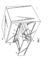
- FIG. 1 of the drawings there is shown a cabinet 10 having three drawers 12, each of which houses apparatus according to the invention.
- the apparatus generally comprises a plurality of containers 14 which are releasably received at a respective station in a container-mounting rack 16, housed one in each drawer 12.
- a compartment 13 separated from the rack 16 by a wall 1 and closed at the top by a removable cover plate 17; the purpose of this compartment will be described hereinbelow.
- the rack 16 is generally frame-like and comprises a base 18 and a support plate 20 arranged substantially parallel thereto and spaced therefrom.
- the upper plate 20 is provided with an array of apertures 22 ( Figure 2) through which the containers 14 are insertable.
- the support plate 20 acts to support the containers in an upright position.
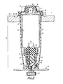
- FIG. 2 shows in greater detail a sample container 14 received and located at a station in the container-mounting rack 16.
- a bucket-shaped containment vessel 24 integrally formed at its base with a spigot 26, which acts as location means for the container 14 and which will be described in greater detail below.
- the upper edge of the containment vessel 24 is turned back on itself to form a collar 28 which hooks over the rim of the aperture 22 in the upper support plate 20.
- the containment vessel 24 serves to catch any inadvertent spillage from the container 14 thus preventing spread of contaminating substances to the rest of the apparatus.
- a seal 30 ensures that no spillage on the upper surface of the plate 20 leaks down into the space between the aperture 22 in the wall and the outer wall of the containment vessel 24.
- An indented circular channel 32 in the support plate 20 and surrounding the collar 28 of the containment vessel helps to catch spills and stop them spreading overthe upper surface of the plate 20.
- the container 14 consists of a substantially cylindrical glass body 34 sealed at both ends by elastomeric bungs 36, 38.
- the lower bung 38 houses a pair of electrodes 40 which make electrical connection with a respective pair of electrical contacts 42 housed in the spigot 26 of the rack 16.
- a generally cylindrical socket member 44 is secured to the lower neck of the container body 34 and holds the bung 38 captive in the neck of the container body 34.
- the socket member 44 is adapted to be received on and located by the spigot 26.
- a key in the form of an axially extending rib 46 on the inner surface of the socket member 44 and this is engageable with a keyway 48 on the spigot 26.
- the apparatus comprises retention means, which consist in the case of the embodiment illustrated in Figures 1 and 2 of a bayonet joint means.
- retention means consist in the case of the embodiment illustrated in Figures 1 and 2 of a bayonet joint means.
- a cap 50 Secured to the upper neck 35 of the container body 34 is a cap 50 having an outwardly extending skirt portion 52, from which projects at least one lug 54 engageable with a slot opening 56 in the collar 28 of the containment vessel 24.
- Projecting either side of the cap 50 is a pair of wings 58 which enable the cap 50 to be turned when engaging or disengaging the bayonet joint means 54, 56.
- the cap 50 is secured to the upper neck 35 of the container body by means of a joint which allows slipping friction therebetween.
- the retention means consist of a screw thread 60 engageable with a threadway 62 on the inner surface of the collar 28 of the containment vessel 24.
- the outer surface of the cap is provided with a knurled region 64.
- FIG. 3 to 5 of the drawings there are shown three consecutive stages during the insertion of a container 14 into the rack 16. Although these three Figures illustrate the threaded version of the retention means, comparable stages of insertion are carried out for the bayonet means of Figure 2.
- a container 14 is first inserted, through the collar 28 and into the containment vessel 24 which guides the container 14 downwardly until the lower edge region of the socket member 44 rests on the upper edge of the spigot 26.
- the rib or key 46 does not quite fully extend to the lower free edge of the socket member to enable the initial location between the socket member 44 and the spigot 26 to take place, as is shown in Figure 3, where the lower end of the rib 46 rests on the upper surface of the spigot 26.
- the container 14 is by then pushed fully home into the position shown in Figure 5. Tests on a sample previously introduced into the container can commence.
- a sample container can be inserted into the rack 16 simply and held there securely and yet be readily released simply by turning the cap 50 to release the threaded connection 60, 62 or bayonet joint 54, 56, either of which are readily operable by the user from above the upper support plate 20, being disposed adjacent the cap 50 of the container 14.
- the base 18 of the rack 16 is formed by a printed circuit board which provides the necessary connections between the electrical contacts 42 at each station and a computer (not shown) which collects, processes and stores the data and which provides a readout of the microbiological growth curve generated by the sample in each of the containers.
- a compartment 13 is provided at the back of each drawer 12.
- the compartment houses an independent power supply and microprocessor 19 to make each drawer as independent as possible of the computer and any power fluctuations.
- a mains supply incorporating a battery may be provided for use in the event of power supply failure so that data logging continues until normal power supply resumes and processor capability is restored.
- the wall 15 and cover plate 17 of the compartment 13 protect the back-up power supply and microprocessor 19 from any inadvertent spillage in the drawer 12.
- heating means such as a coiled heating element disposed at each station, between the upper support plate 20 and the base 18.
- the heating means enable the sample in a container in the rack to be incubated at a selected temperature of between 30°C and 40°C with an accuracy of ⁇ 1 °C.
- the drawer microprocessor may be used to control the pattern of heat distribution in the drawer.
- an LED indicator ad- jacentto each station can also be provision for an LED indicator ad- jacentto each station to show that a container at that station has become «positive», i.e. that a particular concentration of micro-organisms has been reached in that container.
- the vessel 24 can be removed from the rack for cleaning or replacement by releasing the bolt 64 which secures it releasably to the base 18.
- the bolt 64 which secures it releasably to the base 18.
- an 0 ring 66 sealing off this passageway from the base 18.
- a member of the hospital staff takes blood from a patient using a hypodermic syringe and injects the sample imme- diatelyfromthe hypodermic into a container 14through the upper bung 36. Samples from a number of patients can be collected in this way, the relatively robust containers being then carried to the cabinet 10 and inserted easily and reliably into the rack 16. Tests then commence, with results expected in a matter of hours.
- FIG. 1 Illustrated in Figure 1 is a venting plug 70 to which may be inserted through the upper bung 36 of those containers 14 holding samples likely to contain aerobic microbes.
- the cabinet is constructed to give sufficient clearance for the drawers 12 to close when such venting plugs are in use.
- the push-fit plug and socket location means can be interchanged, sothat instead of the spigot 26 being disposed on the rack 16 and the socket member 44 on the container 14, the spigot or plug could be provided on the container and vice versa.
- location means could comprise, instead of a push-fit plug and socket means, a screwthread or bayonet joint means between each container and the rack.
- retention means itself comprises a srew-thread means or bayonet joint means respectively.
- An alternative form of orientation means for a location means which comprises a bayonet joint means may suitably comprise the bayonet joint means being radially or circumferentially offset.
Landscapes
- Chemical & Material Sciences (AREA)
- Wood Science & Technology (AREA)
- Organic Chemistry (AREA)
- Health & Medical Sciences (AREA)
- Life Sciences & Earth Sciences (AREA)
- Engineering & Computer Science (AREA)
- Bioinformatics & Cheminformatics (AREA)
- Zoology (AREA)
- Biochemistry (AREA)
- Microbiology (AREA)
- Biotechnology (AREA)
- Biomedical Technology (AREA)
- General Engineering & Computer Science (AREA)
- General Health & Medical Sciences (AREA)
- Genetics & Genomics (AREA)
- Analytical Chemistry (AREA)
- Sustainable Development (AREA)
- Measuring Or Testing Involving Enzymes Or Micro-Organisms (AREA)
- Automatic Analysis And Handling Materials Therefor (AREA)
- Apparatus Associated With Microorganisms And Enzymes (AREA)
- Farming Of Fish And Shellfish (AREA)
- Investigating Or Analysing Biological Materials (AREA)
- Looms (AREA)
- Air Bags (AREA)
- Medicines Containing Material From Animals Or Micro-Organisms (AREA)
Abstract
Description
- The present invention relates to apparatus for use in detecting micro-organisms in samples of a substance and can be used, for example, for monitoring substances intended for human consumption, such as foods, drinks or pharmaceuticals, or may be used to monitor pathological samples, such as blood, in the laboratory.
- Blood culturing techniques currently used in hospitals include a method in which a sample of blood is cultured in nutrient broth, from which samples are sub-cultured on agar plates at regular intervals. Not only is this method extremely slow with results not being expected for several days, but it is highly labour intensive and requires good aseptic conditions to be maintained throughout.
- A quicker technique uses a machine sold under the trade name Bactec. To use this machine, the sample is exposed to a radioactive substrate which is consumed by the micro-organisms, which then give off radioactive carbon dioxide for detection by the machine. Although this machine gives results in hours, rather than days, hospital personnel may be worried by possible radioactive exposure and waste disposal.
- Electrochemical methods have been proposed which include measuring conductance, impedance or potential difference changes, but known apparatus using these methods is not readily susceptible to hospital use in that the sample bottles are kept at a controlled temperature in a water bath which may become contaminated by spillage. In another known apparatus, instead of sample-holding bottles, special modules are required which are not suitable for filling directly from the hypodermic syringe used to remove blood from a patient, and an intermediate pipetting stage is necessary, with the result that time is wasted, labour is required and spillage, and hence contamination of personnel or equipment, is possible.
- In our British Patent Specification No.2, 142,433B, we have described apparatus for use in detecting micro-organisms in any one of a plurality of samples, comprising a plurality of containers for the samples, each container having in its base at least one electrode contactable with the sample therein, and a container-mounting member having means for receiving and for locating each of said containers at a respective one af an array of stations, the container-mounting member comprising a base provided with electrical contact means at each station for electrical connection with the electrode of a container received at that station.
- As a result of placing the electrodes in the base of the sample containers, there are no wires protruding from the containers which may become contaminated or tangled.
- It is an object of the present invention to provide apparatus for detecting micro-organisms which is convenient to use and easy to keep clean in a hospital environment.
- According to the present invention there is provided apparatus for use in detecting micro-organisms in any one of a plurality of samples, comprising a plurality of containers for the samples, each container having in its base at least one electrode contactable with the sample therein, and a container-mounting member having means for receiving and for locating each of the containers at a respective one of an array of stations, the container-mounting member comprising a base provided with electrical contact means at each station for electrical connection with the electrode of a container received at that station; characterised in that the container-mounting member is in the form of a rack having upper support means for the containers spaced upwardly from its base, and in that releasable retention means, for retaining a container at a station, are adapted to cc-3perate with the upper support means are operable from above said upper support means.
- Because the retention means are operable from above the upper support means of the container-mounting rack, access to each container is good with the result that the containers are readily inserted and removed from their stations in the rack.
- The retention means may comprise either means for screw-threaded engagement or bayonet engagement means between each container and the upper support means.
- Suitably, the location means for locating a said container at one of said stations is disposed adjacent the respective electrical contact means at that station. As a result, there is good positive location of a container in the rack where it is most needed to ensure that good electrical contact between the containers and the rack is established.
- The location means suitably comprises a push-fit plug and socket means, which is preferably rotationally independent of the retention means.
- Suitably, where each container has more than one electrode in its base, with a respective number of electrical contacts being provided at each station, the apparatus may further comprise orientation means.for orienting the container at the respective station so that the electrodes make electrical connection only with their respective electrical contacts.
- In the case where the location means comprises a push-fit plug and socket means, the orientation means may comprise a mutually engageable key and keyway on the plug and socket means. Since the retention means is rotationally independent of the push-fit plug and socket means, the container may be retained at a station in the rack without rotational interference presented by the engagement between the key and keyway on the plug and socket means.
- Suitably, the container-mounting rack comprises heating means for incubating samples in containers which are received in the rack.
- The container-mounting rack may further comprise a containment vessel at each station adapted to surround a container received at that station and contain spillage therefrom. Suitably, each said vessel is adapted to be releasably attached to the container-mounting rack.
- The upper support means of the rack may comprise substantially a horizontal plate provided with an indented region at each station for retaining spillage from a container at or adjacent that station.
- Embodiments of the invention will now be' described with reference to the accompanying drawings wherein:
- Figure 1 is a perspective view of a three drawer cabinet, each drawer housing apparatus according to the invention;
- Figure 2 is an enlarged longitudinal cross-section through one of the sample containers retained at a station in the rack shown in Figure 1; and
- Figures 3 to 5 illustrate successive stages of insertion of an alternative embodiment of sample container into the rack.
- Referring to Figure 1 of the drawings, there is shown a
cabinet 10 having threedrawers 12, each of which houses apparatus according to the invention. The apparatus generally comprises a plurality ofcontainers 14 which are releasably received at a respective station in a container-mounting rack 16, housed one in eachdrawer 12. At the back of eachdrawer 12 is acompartment 13 separated from therack 16 by a wall 1 and closed at the top by aremovable cover plate 17; the purpose of this compartment will be described hereinbelow. - The
rack 16 is generally frame-like and comprises abase 18 and asupport plate 20 arranged substantially parallel thereto and spaced therefrom. Theupper plate 20 is provided with an array of apertures 22 (Figure 2) through which thecontainers 14 are insertable. Thesupport plate 20 acts to support the containers in an upright position. - Figure 2 shows in greater detail a
sample container 14 received and located at a station in the container-mounting rack 16. Extending between thebase 18 andupper support plate 20 at each station is a bucket-shaped containment vessel 24 integrally formed at its base with aspigot 26, which acts as location means for thecontainer 14 and which will be described in greater detail below. The upper edge of thecontainment vessel 24 is turned back on itself to form acollar 28 which hooks over the rim of theaperture 22 in theupper support plate 20. Thecontainment vessel 24 serves to catch any inadvertent spillage from thecontainer 14 thus preventing spread of contaminating substances to the rest of the apparatus. Aseal 30 ensures that no spillage on the upper surface of theplate 20 leaks down into the space between theaperture 22 in the wall and the outer wall of thecontainment vessel 24. An indentedcircular channel 32 in thesupport plate 20 and surrounding thecollar 28 of the containment vessel helps to catch spills and stop them spreading overthe upper surface of theplate 20. - The
container 14 consists of a substantiallycylindrical glass body 34 sealed at both ends byelastomeric bungs lower bung 38 houses a pair ofelectrodes 40 which make electrical connection with a respective pair ofelectrical contacts 42 housed in thespigot 26 of therack 16. By means of a crown fitting, a generallycylindrical socket member 44 is secured to the lower neck of thecontainer body 34 and holds thebung 38 captive in the neck of thecontainer body 34. Thesocket member 44 is adapted to be received on and located by thespigot 26. A detailed description of the construction of thecontainer 14 and its location on thespigot 26 with resultant electrical connection between theelectrodes 40 of thecontainer 14 and theelectrical contacts 42 of thespigot 26 is given in our British Patent Application No. 8,506,097, published under No. 2 171 982. - To ensure correct orientation of the
electrodes 40 with their respectiveelectrical contacts 42, there is provided a key in the form of an axially extendingrib 46 on the inner surface of thesocket member 44 and this is engageable with akeyway 48 on thespigot 26. - To ensure that a
container 14 is retained within therack 16, thus maintaining good and reliable electrical contact between theelectrodes 40 andcontacts 42, the apparatus comprises retention means, which consist in the case of the embodiment illustrated in Figures 1 and 2 of a bayonet joint means. Secured to theupper neck 35 of thecontainer body 34 is acap 50 having an outwardly extendingskirt portion 52, from which projects at least onelug 54 engageable with a slot opening 56 in thecollar 28 of thecontainment vessel 24. Projecting either side of thecap 50 is a pair ofwings 58 which enable thecap 50 to be turned when engaging or disengaging the bayonet joint means 54, 56. - To allow the retention means to operate, whilst enabling the push-
fit socket member 44 to be urged vertically downwards on to thespigot 26 once the key andkeyway cap 50 is secured to theupper neck 35 of the container body by means of a joint which allows slipping friction therebetween. - In an alternative embodiment, illustrated in Figures 3 to 5, the retention means consist of a
screw thread 60 engageable with athreadway 62 on the inner surface of thecollar 28 of thecontainment vessel 24. Instead of thewings 58, the outer surface of the cap is provided with aknurled region 64. - Referring to Figures 3 to 5 of the drawings, there are shown three consecutive stages during the insertion of a
container 14 into therack 16. Although these three Figures illustrate the threaded version of the retention means, comparable stages of insertion are carried out for the bayonet means of Figure 2. Acontainer 14 is first inserted, through thecollar 28 and into thecontainment vessel 24 which guides thecontainer 14 downwardly until the lower edge region of thesocket member 44 rests on the upper edge of thespigot 26. The rib orkey 46 does not quite fully extend to the lower free edge of the socket member to enable the initial location between thesocket member 44 and thespigot 26 to take place, as is shown in Figure 3, where the lower end of therib 46 rests on the upper surface of thespigot 26. - The user now turns the
cap 50 and, because of the friction which exists between thecap 50 and theupper neck 35 of thecontainer 14, the container itself rotates about its axis until therib 46 becomes aligned with thekeyway 48. The user can then push the container downwardly, but only so far until thethreaded region 60 of thecap 50 rests at the top of thecollar 28 i.e. in the position shown in Figure 4. - The user then operates the retention means by engaging the
thread 60 and threadway 62 (or, for the Figure 2 embodiment, thebayonet joint 54, 56) and, because the rib andkeyway socket member 44 on thespigot 26, thecontainer body 34 becomes non-rotational and thecap 50 slips relative to theneck 35 of Shecontainer 14 enabling thecap 50 to rotate into threaded or bayonet engagement with thecollar 28 of thecontainment vessel 24. - Once the retention means are fully operational, the
container 14 is by then pushed fully home into the position shown in Figure 5. Tests on a sample previously introduced into the container can commence. - Thus a sample container can be inserted into the
rack 16 simply and held there securely and yet be readily released simply by turning thecap 50 to release the threadedconnection bayonet joint upper support plate 20, being disposed adjacent thecap 50 of thecontainer 14. - The
base 18 of therack 16 is formed by a printed circuit board which provides the necessary connections between theelectrical contacts 42 at each station and a computer (not shown) which collects, processes and stores the data and which provides a readout of the microbiological growth curve generated by the sample in each of the containers. - As mentioned above, in Figure 1 it can be seen that a
compartment 13 is provided at the back of eachdrawer 12. The compartment houses an independent power supply andmicroprocessor 19 to make each drawer as independent as possible of the computer and any power fluctuations. For example a mains supply incorporating a battery may be provided for use in the event of power supply failure so that data logging continues until normal power supply resumes and processor capability is restored. Thewall 15 andcover plate 17 of thecompartment 13 protect the back-up power supply andmicroprocessor 19 from any inadvertent spillage in thedrawer 12. - Not shown are heating means, such as a coiled heating element disposed at each station, between the
upper support plate 20 and thebase 18. The heating means enable the sample in a container in the rack to be incubated at a selected temperature of between 30°C and 40°C with an accuracy of ± 1 °C. The drawer microprocessor may be used to control the pattern of heat distribution in the drawer. - There can also be provision for an LED indicator ad- jacentto each station to show that a container at that station has become «positive», i.e. that a particular concentration of micro-organisms has been reached in that container.
- In case any spillage should occur down into the containment vessel, the
vessel 24 can be removed from the rack for cleaning or replacement by releasing thebolt 64 which secures it releasably to thebase 18. To prevent any potential ingress of spilt sample via the passage provided in thespigot 26 for theelectrical contacts 42, there is provided an 0ring 66 sealing off this passageway from thebase 18. - In use of the apparatus for monitoring blood, a member of the hospital staff takes blood from a patient using a hypodermic syringe and injects the sample imme- diatelyfromthe hypodermic into a container 14through the
upper bung 36. Samples from a number of patients can be collected in this way, the relatively robust containers being then carried to thecabinet 10 and inserted easily and reliably into therack 16. Tests then commence, with results expected in a matter of hours. - Illustrated in Figure 1 is a venting
plug 70 to which may be inserted through theupper bung 36 of thosecontainers 14 holding samples likely to contain aerobic microbes. Clearly, the cabinet is constructed to give sufficient clearance for thedrawers 12 to close when such venting plugs are in use. - Modifications to the illustrated apparatus are also envisaged. For instance, the push-fit plug and socket location means can be interchanged, sothat instead of the
spigot 26 being disposed on therack 16 and thesocket member 44 on thecontainer 14, the spigot or plug could be provided on the container and vice versa. - Furthermore, the location means could comprise, instead of a push-fit plug and socket means, a screwthread or bayonet joint means between each container and the rack. Clearly, there alternative embodiments would be suitable where the retention means itself comprises a srew-thread means or bayonet joint means respectively.
- An alternative form of orientation means for a location means which comprises a bayonet joint means may suitably comprise the bayonet joint means being radially or circumferentially offset.
Claims (12)
Priority Applications (1)
| Application Number | Priority Date | Filing Date | Title |
|---|---|---|---|
| AT87300811T ATE49480T1 (en) | 1986-02-06 | 1987-01-29 | DEVICE FOR DETECTING MICROORGANISMS. |
Applications Claiming Priority (2)
| Application Number | Priority Date | Filing Date | Title |
|---|---|---|---|
| GB8602980 | 1986-02-06 | ||
| GB8602980A GB2186366B (en) | 1986-02-06 | 1986-02-06 | Improvements in or relating to apparatus for detecting micro-organisms |
Publications (3)
| Publication Number | Publication Date |
|---|---|
| EP0233024A2 EP0233024A2 (en) | 1987-08-19 |
| EP0233024A3 EP0233024A3 (en) | 1988-08-03 |
| EP0233024B1 true EP0233024B1 (en) | 1990-01-10 |
Family
ID=10592637
Family Applications (1)
| Application Number | Title | Priority Date | Filing Date |
|---|---|---|---|
| EP87300811A Expired - Lifetime EP0233024B1 (en) | 1986-02-06 | 1987-01-29 | Apparatus for detecting micro-organisms |
Country Status (15)
| Country | Link |
|---|---|
| US (1) | US4789635A (en) |
| EP (1) | EP0233024B1 (en) |
| JP (1) | JPS62191764A (en) |
| AT (1) | ATE49480T1 (en) |
| AU (1) | AU604670B2 (en) |
| CS (1) | CS75487A2 (en) |
| DE (1) | DE3761403D1 (en) |
| DK (1) | DK55987A (en) |
| ES (1) | ES2013290B3 (en) |
| FI (1) | FI870459A7 (en) |
| GB (1) | GB2186366B (en) |
| HU (1) | HU194412B (en) |
| IE (1) | IE870262L (en) |
| NO (1) | NO870439L (en) |
| ZA (1) | ZA87590B (en) |
Families Citing this family (11)
| Publication number | Priority date | Publication date | Assignee | Title |
|---|---|---|---|---|
| GB2188146B (en) * | 1986-03-19 | 1990-11-14 | Metal Box Plc | Apparatus for detecting micro-organisms |
| GB8822586D0 (en) * | 1988-09-27 | 1988-11-02 | Whitley Don Scient Ltd | Testing bacteriological activity |
| US5643742A (en) * | 1990-04-03 | 1997-07-01 | Cellstat Technologies, Inc. | System for electronically monitoring and recording cell cultures |
| EP1405919B1 (en) * | 1992-07-29 | 2008-03-12 | Cellstat Technologies, Inc. | A method for electronically monitoring and recording cell cultures |
| EP0655086B1 (en) * | 1992-07-29 | 2003-12-17 | Cellstat Technologies, Inc. | An improved system for electronically monitoring and recording cell cultures |
| US5432086A (en) * | 1992-11-18 | 1995-07-11 | Sy-Lab Vertriebsgellschaft M.B.H. | Apparatus for the automatic monitoring of microorganism culture |
| US20060256599A1 (en) * | 2005-03-22 | 2006-11-16 | Malin Patricia J | Database of electronically profiled cells and methods for generating and using same |
| WO2012147463A1 (en) * | 2011-04-28 | 2012-11-01 | 株式会社日立製作所 | Cell cultivation container and cell culturing apparatus |
| US9170193B2 (en) | 2013-06-06 | 2015-10-27 | General Electric Company | Detecting coolant leaks in turbine generators |
| US9097657B2 (en) | 2013-07-23 | 2015-08-04 | General Electric Company | Leak detection of stator liquid cooling system |
| US10563164B1 (en) * | 2015-10-08 | 2020-02-18 | Charm Sciences, Inc. | Plate reader |
Family Cites Families (9)
| Publication number | Priority date | Publication date | Assignee | Title |
|---|---|---|---|---|
| US3526125A (en) * | 1967-12-19 | 1970-09-01 | Gilford Instr Labor Inc | Test sample identifying system and apparatus for use in connection therewith |
| US3680967A (en) * | 1970-09-14 | 1972-08-01 | Technicon Instr | Self-locating sample receptacle having integral identification label |
| US4057148A (en) * | 1974-06-25 | 1977-11-08 | G. D. Searle & Co. | Multiple sample support assembly and apparatus for facilitating radioimmunoassays and the like |
| DE2544533A1 (en) * | 1975-10-04 | 1977-04-07 | Bayer Ag | STORAGE DEVICE FOR STORAGE OF SAMPLE CONTAINERS |
| US4290550A (en) * | 1980-02-19 | 1981-09-22 | Beckman Instruments, Inc. | Modular supporting cap and spacer for centrifuge tubes |
| US4310488A (en) * | 1980-05-19 | 1982-01-12 | Hoffmann-La Roche Inc. | Sample or reagent container for analyzers |
| US4517851A (en) * | 1983-05-20 | 1985-05-21 | Becton Dickinson And Company | System for controlling septum damage |
| GB2142433B (en) * | 1983-06-29 | 1986-10-29 | Metal Box Plc | Apparatus for detecting micr-organisms |
| GB2171982B (en) * | 1985-03-08 | 1989-01-11 | Metal Box Plc | Containers for use in detecting micro-organisms |
-
1986
- 1986-02-06 GB GB8602980A patent/GB2186366B/en not_active Expired
-
1987
- 1987-01-20 US US07/004,895 patent/US4789635A/en not_active Expired - Fee Related
- 1987-01-20 AU AU67838/87A patent/AU604670B2/en not_active Expired - Fee Related
- 1987-01-27 ZA ZA87590A patent/ZA87590B/en unknown
- 1987-01-29 EP EP87300811A patent/EP0233024B1/en not_active Expired - Lifetime
- 1987-01-29 AT AT87300811T patent/ATE49480T1/en active
- 1987-01-29 DE DE8787300811T patent/DE3761403D1/en not_active Expired - Lifetime
- 1987-01-29 ES ES87300811T patent/ES2013290B3/en not_active Expired - Lifetime
- 1987-02-02 IE IE870262A patent/IE870262L/en unknown
- 1987-02-03 FI FI870459A patent/FI870459A7/en not_active Application Discontinuation
- 1987-02-03 DK DK055987A patent/DK55987A/en not_active Application Discontinuation
- 1987-02-04 NO NO870439A patent/NO870439L/en unknown
- 1987-02-05 CS CS87754A patent/CS75487A2/en unknown
- 1987-02-05 HU HU87403A patent/HU194412B/en not_active IP Right Cessation
- 1987-02-06 JP JP62026206A patent/JPS62191764A/en active Pending
Also Published As
| Publication number | Publication date |
|---|---|
| ZA87590B (en) | 1987-10-28 |
| EP0233024A2 (en) | 1987-08-19 |
| GB8602980D0 (en) | 1986-03-12 |
| FI870459A7 (en) | 1987-08-08 |
| HUT42864A (en) | 1987-08-28 |
| AU6783887A (en) | 1987-08-13 |
| US4789635A (en) | 1988-12-06 |
| DK55987D0 (en) | 1987-02-03 |
| NO870439D0 (en) | 1987-02-04 |
| DE3761403D1 (en) | 1990-02-15 |
| JPS62191764A (en) | 1987-08-22 |
| DK55987A (en) | 1987-08-07 |
| GB2186366B (en) | 1989-11-22 |
| ES2013290B3 (en) | 1990-05-01 |
| EP0233024A3 (en) | 1988-08-03 |
| ATE49480T1 (en) | 1990-01-15 |
| AU604670B2 (en) | 1991-01-03 |
| GB2186366A (en) | 1987-08-12 |
| HU194412B (en) | 1988-01-28 |
| NO870439L (en) | 1987-08-07 |
| FI870459L (en) | 1987-08-07 |
| IE870262L (en) | 1987-08-06 |
| CS75487A2 (en) | 1990-10-12 |
| FI870459A0 (en) | 1987-02-03 |
Similar Documents
| Publication | Publication Date | Title |
|---|---|---|
| US4789635A (en) | Apparatus for detecting micro-organisms | |
| CA1256360A (en) | Apparatus and method for determining the effectiveness of sterlization | |
| JP2562916B2 (en) | Container for microbial culture medium | |
| EP2114571B1 (en) | Liquid testing assembly | |
| CA1182729A (en) | Contamination-free sterilization indicating system | |
| CA2397688C (en) | Liquid specimen collection system | |
| US5863752A (en) | Methods and apparatus for monitoring the growth of microorganisms in liquid culture | |
| CN107529744B (en) | Medical Sample Shipping Containers | |
| WO2011108818A2 (en) | Container with a spoon for the prevention of reagent contamination | |
| WO1983000932A1 (en) | Reagent storage and delivery system | |
| US20120021452A1 (en) | Belt Agitation System For Culture Bottles | |
| US4187149A (en) | Cell culture sampling system | |
| EP0194073B1 (en) | Containers for use in detecting micro-organisms | |
| CN209921901U (en) | Hanging type cotton swab storage box | |
| CN216445387U (en) | Tumor cell 3D culture apparatus | |
| CN120005717B (en) | A microbial detection device and its detection method | |
| AU596396B2 (en) | Apparatus for detecting micro-organisms | |
| CN111272963A (en) | Hospital wastewater detection device and method | |
| CN220371061U (en) | Filter beaker kit for laboratory | |
| CN216998403U (en) | Pathogen activity detection system in medical wastewater | |
| WO2019180057A1 (en) | System for observation of media dissolution and/or bacterial growth in a transparent bag | |
| CN211168186U (en) | Sample save set for medical science inspection | |
| WO1997047728A1 (en) | Monitoring the contents of sealed containers | |
| WO2005086816A2 (en) | Liquid sampling apparatus and method of using same | |
| Tisserat et al. | Automation of the surface sterilization system procedure |
Legal Events
| Date | Code | Title | Description |
|---|---|---|---|
| PUAI | Public reference made under article 153(3) epc to a published international application that has entered the european phase |
Free format text: ORIGINAL CODE: 0009012 |
|
| 17P | Request for examination filed |
Effective date: 19870220 |
|
| AK | Designated contracting states |
Kind code of ref document: A2 Designated state(s): AT BE CH DE ES FR GB IT LI LU NL SE |
|
| PUAL | Search report despatched |
Free format text: ORIGINAL CODE: 0009013 |
|
| AK | Designated contracting states |
Kind code of ref document: A3 Designated state(s): AT BE CH DE ES FR GB IT LI LU NL SE |
|
| 17Q | First examination report despatched |
Effective date: 19890207 |
|
| RAP1 | Party data changed (applicant data changed or rights of an application transferred) |
Owner name: MB GROUP PLC |
|
| RAP1 | Party data changed (applicant data changed or rights of an application transferred) |
Owner name: CMB PACKAGING (UK) LIMITED |
|
| RBV | Designated contracting states (corrected) |
Designated state(s): AT BE CH DE ES FR GB IT LI NL SE |
|
| GRAA | (expected) grant |
Free format text: ORIGINAL CODE: 0009210 |
|
| AK | Designated contracting states |
Kind code of ref document: B1 Designated state(s): AT BE CH DE ES FR GB IT LI NL SE |
|
| PG25 | Lapsed in a contracting state [announced via postgrant information from national office to epo] |
Ref country code: NL Effective date: 19900110 Ref country code: AT Effective date: 19900110 |
|
| REF | Corresponds to: |
Ref document number: 49480 Country of ref document: AT Date of ref document: 19900115 Kind code of ref document: T |
|
| ITF | It: translation for a ep patent filed | ||
| RBV | Designated contracting states (corrected) |
Designated state(s): AT BE CH DE ES FR IT LI NL SE |
|
| PG25 | Lapsed in a contracting state [announced via postgrant information from national office to epo] |
Ref country code: SE Effective date: 19900130 |
|
| PG25 | Lapsed in a contracting state [announced via postgrant information from national office to epo] |
Ref country code: LI Effective date: 19900131 Ref country code: CH Effective date: 19900131 Ref country code: BE Effective date: 19900131 |
|
| REF | Corresponds to: |
Ref document number: 3761403 Country of ref document: DE Date of ref document: 19900215 |
|
| ET | Fr: translation filed | ||
| NLV1 | Nl: lapsed or annulled due to failure to fulfill the requirements of art. 29p and 29m of the patents act | ||
| BERE | Be: lapsed |
Owner name: CMB PACKAGING (UK) LTD Effective date: 19900131 |
|
| REG | Reference to a national code |
Ref country code: CH Ref legal event code: PL |
|
| PLBE | No opposition filed within time limit |
Free format text: ORIGINAL CODE: 0009261 |
|
| STAA | Information on the status of an ep patent application or granted ep patent |
Free format text: STATUS: NO OPPOSITION FILED WITHIN TIME LIMIT |
|
| 26N | No opposition filed | ||
| ITTA | It: last paid annual fee | ||
| PGFP | Annual fee paid to national office [announced via postgrant information from national office to epo] |
Ref country code: FR Payment date: 19911209 Year of fee payment: 6 |
|
| PGFP | Annual fee paid to national office [announced via postgrant information from national office to epo] |
Ref country code: DE Payment date: 19911213 Year of fee payment: 6 |
|
| PGFP | Annual fee paid to national office [announced via postgrant information from national office to epo] |
Ref country code: ES Payment date: 19920113 Year of fee payment: 6 |
|
| PG25 | Lapsed in a contracting state [announced via postgrant information from national office to epo] |
Ref country code: ES Free format text: LAPSE BECAUSE OF NON-PAYMENT OF DUE FEES Effective date: 19930130 |
|
| PG25 | Lapsed in a contracting state [announced via postgrant information from national office to epo] |
Ref country code: FR Effective date: 19930930 |
|
| PG25 | Lapsed in a contracting state [announced via postgrant information from national office to epo] |
Ref country code: DE Effective date: 19931001 |
|
| REG | Reference to a national code |
Ref country code: FR Ref legal event code: ST |
|
| EUG | Se: european patent has lapsed |
Ref document number: 87300811.4 Effective date: 19910110 |
|
| REG | Reference to a national code |
Ref country code: ES Ref legal event code: FD2A Effective date: 19990201 |
|
| PG25 | Lapsed in a contracting state [announced via postgrant information from national office to epo] |
Ref country code: IT Free format text: LAPSE BECAUSE OF NON-PAYMENT OF DUE FEES;WARNING: LAPSES OF ITALIAN PATENTS WITH EFFECTIVE DATE BEFORE 2007 MAY HAVE OCCURRED AT ANY TIME BEFORE 2007. THE CORRECT EFFECTIVE DATE MAY BE DIFFERENT FROM THE ONE RECORDED. Effective date: 20050129 |