EP0232978A2 - Liquid self-lubricating bearing system - Google Patents
Liquid self-lubricating bearing system Download PDFInfo
- Publication number
- EP0232978A2 EP0232978A2 EP87300230A EP87300230A EP0232978A2 EP 0232978 A2 EP0232978 A2 EP 0232978A2 EP 87300230 A EP87300230 A EP 87300230A EP 87300230 A EP87300230 A EP 87300230A EP 0232978 A2 EP0232978 A2 EP 0232978A2
- Authority
- EP
- European Patent Office
- Prior art keywords
- shaft
- lubricating system
- pumper
- reservoir
- bore
- Prior art date
- Legal status (The legal status is an assumption and is not a legal conclusion. Google has not performed a legal analysis and makes no representation as to the accuracy of the status listed.)
- Granted
Links
Images
Classifications
-
- F—MECHANICAL ENGINEERING; LIGHTING; HEATING; WEAPONS; BLASTING
- F16—ENGINEERING ELEMENTS AND UNITS; GENERAL MEASURES FOR PRODUCING AND MAINTAINING EFFECTIVE FUNCTIONING OF MACHINES OR INSTALLATIONS; THERMAL INSULATION IN GENERAL
- F16C—SHAFTS; FLEXIBLE SHAFTS; ELEMENTS OR CRANKSHAFT MECHANISMS; ROTARY BODIES OTHER THAN GEARING ELEMENTS; BEARINGS
- F16C19/00—Bearings with rolling contact, for exclusively rotary movement
- F16C19/22—Bearings with rolling contact, for exclusively rotary movement with bearing rollers essentially of the same size in one or more circular rows, e.g. needle bearings
- F16C19/34—Bearings with rolling contact, for exclusively rotary movement with bearing rollers essentially of the same size in one or more circular rows, e.g. needle bearings for both radial and axial load
- F16C19/36—Bearings with rolling contact, for exclusively rotary movement with bearing rollers essentially of the same size in one or more circular rows, e.g. needle bearings for both radial and axial load with a single row of rollers
-
- F—MECHANICAL ENGINEERING; LIGHTING; HEATING; WEAPONS; BLASTING
- F16—ENGINEERING ELEMENTS AND UNITS; GENERAL MEASURES FOR PRODUCING AND MAINTAINING EFFECTIVE FUNCTIONING OF MACHINES OR INSTALLATIONS; THERMAL INSULATION IN GENERAL
- F16C—SHAFTS; FLEXIBLE SHAFTS; ELEMENTS OR CRANKSHAFT MECHANISMS; ROTARY BODIES OTHER THAN GEARING ELEMENTS; BEARINGS
- F16C19/00—Bearings with rolling contact, for exclusively rotary movement
- F16C19/54—Systems consisting of a plurality of bearings with rolling friction
- F16C19/541—Systems consisting of juxtaposed rolling bearings including at least one angular contact bearing
- F16C19/542—Systems consisting of juxtaposed rolling bearings including at least one angular contact bearing with two rolling bearings with angular contact
-
- F—MECHANICAL ENGINEERING; LIGHTING; HEATING; WEAPONS; BLASTING
- F16—ENGINEERING ELEMENTS AND UNITS; GENERAL MEASURES FOR PRODUCING AND MAINTAINING EFFECTIVE FUNCTIONING OF MACHINES OR INSTALLATIONS; THERMAL INSULATION IN GENERAL
- F16C—SHAFTS; FLEXIBLE SHAFTS; ELEMENTS OR CRANKSHAFT MECHANISMS; ROTARY BODIES OTHER THAN GEARING ELEMENTS; BEARINGS
- F16C33/00—Parts of bearings; Special methods for making bearings or parts thereof
- F16C33/30—Parts of ball or roller bearings
- F16C33/66—Special parts or details in view of lubrication
- F16C33/6637—Special parts or details in view of lubrication with liquid lubricant
- F16C33/664—Retaining the liquid in or near the bearing
-
- F—MECHANICAL ENGINEERING; LIGHTING; HEATING; WEAPONS; BLASTING
- F16—ENGINEERING ELEMENTS AND UNITS; GENERAL MEASURES FOR PRODUCING AND MAINTAINING EFFECTIVE FUNCTIONING OF MACHINES OR INSTALLATIONS; THERMAL INSULATION IN GENERAL
- F16C—SHAFTS; FLEXIBLE SHAFTS; ELEMENTS OR CRANKSHAFT MECHANISMS; ROTARY BODIES OTHER THAN GEARING ELEMENTS; BEARINGS
- F16C33/00—Parts of bearings; Special methods for making bearings or parts thereof
- F16C33/30—Parts of ball or roller bearings
- F16C33/66—Special parts or details in view of lubrication
- F16C33/6637—Special parts or details in view of lubrication with liquid lubricant
- F16C33/6659—Details of supply of the liquid to the bearing, e.g. passages or nozzles
- F16C33/667—Details of supply of the liquid to the bearing, e.g. passages or nozzles related to conditioning, e.g. cooling, filtering
-
- F—MECHANICAL ENGINEERING; LIGHTING; HEATING; WEAPONS; BLASTING
- F16—ENGINEERING ELEMENTS AND UNITS; GENERAL MEASURES FOR PRODUCING AND MAINTAINING EFFECTIVE FUNCTIONING OF MACHINES OR INSTALLATIONS; THERMAL INSULATION IN GENERAL
- F16C—SHAFTS; FLEXIBLE SHAFTS; ELEMENTS OR CRANKSHAFT MECHANISMS; ROTARY BODIES OTHER THAN GEARING ELEMENTS; BEARINGS
- F16C33/00—Parts of bearings; Special methods for making bearings or parts thereof
- F16C33/30—Parts of ball or roller bearings
- F16C33/66—Special parts or details in view of lubrication
- F16C33/6637—Special parts or details in view of lubrication with liquid lubricant
- F16C33/6659—Details of supply of the liquid to the bearing, e.g. passages or nozzles
- F16C33/6674—Details of supply of the liquid to the bearing, e.g. passages or nozzles related to the amount supplied, e.g. gaps to restrict flow of the liquid
-
- F—MECHANICAL ENGINEERING; LIGHTING; HEATING; WEAPONS; BLASTING
- F16—ENGINEERING ELEMENTS AND UNITS; GENERAL MEASURES FOR PRODUCING AND MAINTAINING EFFECTIVE FUNCTIONING OF MACHINES OR INSTALLATIONS; THERMAL INSULATION IN GENERAL
- F16C—SHAFTS; FLEXIBLE SHAFTS; ELEMENTS OR CRANKSHAFT MECHANISMS; ROTARY BODIES OTHER THAN GEARING ELEMENTS; BEARINGS
- F16C35/00—Rigid support of bearing units; Housings, e.g. caps, covers
- F16C35/04—Rigid support of bearing units; Housings, e.g. caps, covers in the case of ball or roller bearings
- F16C35/042—Housings for rolling element bearings for rotary movement
- F16C35/047—Housings for rolling element bearings for rotary movement with a base plate substantially parallel to the axis of rotation, e.g. horizontally mounted pillow blocks
-
- F—MECHANICAL ENGINEERING; LIGHTING; HEATING; WEAPONS; BLASTING
- F16—ENGINEERING ELEMENTS AND UNITS; GENERAL MEASURES FOR PRODUCING AND MAINTAINING EFFECTIVE FUNCTIONING OF MACHINES OR INSTALLATIONS; THERMAL INSULATION IN GENERAL
- F16N—LUBRICATING
- F16N39/00—Arrangements for conditioning of lubricants in the lubricating system
- F16N39/06—Arrangements for conditioning of lubricants in the lubricating system by filtration
-
- F—MECHANICAL ENGINEERING; LIGHTING; HEATING; WEAPONS; BLASTING
- F16—ENGINEERING ELEMENTS AND UNITS; GENERAL MEASURES FOR PRODUCING AND MAINTAINING EFFECTIVE FUNCTIONING OF MACHINES OR INSTALLATIONS; THERMAL INSULATION IN GENERAL
- F16N—LUBRICATING
- F16N7/00—Arrangements for supplying oil or unspecified lubricant from a stationary reservoir or the equivalent in or on the machine or member to be lubricated
- F16N7/14—Arrangements for supplying oil or unspecified lubricant from a stationary reservoir or the equivalent in or on the machine or member to be lubricated the lubricant being conveyed from the reservoir by mechanical means
- F16N7/16—Arrangements for supplying oil or unspecified lubricant from a stationary reservoir or the equivalent in or on the machine or member to be lubricated the lubricant being conveyed from the reservoir by mechanical means the oil being carried up by a lifting device
- F16N7/24—Arrangements for supplying oil or unspecified lubricant from a stationary reservoir or the equivalent in or on the machine or member to be lubricated the lubricant being conveyed from the reservoir by mechanical means the oil being carried up by a lifting device with discs, rollers, belts or the like contacting the shaft to be lubricated
-
- F—MECHANICAL ENGINEERING; LIGHTING; HEATING; WEAPONS; BLASTING
- F16—ENGINEERING ELEMENTS AND UNITS; GENERAL MEASURES FOR PRODUCING AND MAINTAINING EFFECTIVE FUNCTIONING OF MACHINES OR INSTALLATIONS; THERMAL INSULATION IN GENERAL
- F16N—LUBRICATING
- F16N39/00—Arrangements for conditioning of lubricants in the lubricating system
- F16N39/06—Arrangements for conditioning of lubricants in the lubricating system by filtration
- F16N2039/065—Arrangements for conditioning of lubricants in the lubricating system by filtration inlet foot filter
Definitions
- This invention generally relates to self-lubricating bearings and, more particularly, to continuously self-lubricating and self cleansing, non-friction bearings which support a rotatable shaft.
- Shaft-support, non-friction bearings are characterized by an inner race which rotates with the shaft, an outer race which is stationary, and non-friction bearings that rotate between the races.
- the lubricant is typically grease.
- a bearing supporting the arbor shaft of a water-cooled, concrete cutting saw uses a single lip seal which allows grease, moisture, and accumulated dirt to be flushed from the bearing.
- Such a bearing normally overheats in operation and when it cools, debris and moisture around the seals are drawn into the bearing causing corrosion and mechanical damage.
- mist lubricating system which utilizes a source of regulated compressed air, an oil reservoir, a mist generator, a mist-to-oil condenser, a nozzle to force the condensed oil jet into the bearing, and a pump for returning the oil from the bearing back to the oil reservoir.
- a mist system is bulky, impractical and too expensive for use with most portable machines such as concrete saws and the like.
- a mist system which does not require a source of compressed air is described in U.S patent No. 2,950,943. It uses an oil reservoir situated below a slinger arm that is coupled to the rotatable shaft. The slinger splashes oil and creates a mist some of which is intended to reach the rotating bearing surfaces. This mist process provides irregular and non-uniform lubrication and, even at best, it does not sufficiently lubricate nor cleanse the wear products from the bearings.
- the lubricating system comprises a casing having a bore. At least one bearing in the bore supports a rotatable shaft which extends through the bearing and the bore. The bore is sealed off from the ambient by a pair of end seals.
- a pumper element is mounted in the bore for rotation with the shaft and the pumper element when rotating with the shaft causes a lubricant to circulate between a lubricant reservoir and the bearing.
- At least one arcuate channel is preferably within the wall of the bore, and the pumper element is concentrically mounted on the shaft opposite to the channel. The channel preferably gradually tapers outwardly over an arcuate extent.
- the reservoir contains a filter element.
- a well is in the wall of the bore near the bearing and the pumper element rotates within the well which, in use, accumulates the lubricant, and as the shaft starts to rotate, lubricant from the reservoir is sucked into the well thereby establishing uniform lubricant circulation across the bearing elements.
- FIG.1-5 One embodiment of the self-lubricating bearing system of this invention, generally designated as 1 (FIGS.1-5), is entirely enclosed in a unitary casing 2 having a main bore 3 and a longitudinal axis 5 (FIG.4).
- Bore 3 houses a horizontal sleeve shaft 4 whose axis of rotation is coaxial with the bore's main axis 5 (FIGS. 1-2).
- Shaft 4 is supported for rotation by a pair of suitable bearings 6,6′ mounted back-to-back. While two bearings are illustrated, only one such bearing can be used.
- Each bearing 6 or 6′ has suitable bearing elements 7 that rotate between an inner race 9 secured to shaft 4 and a stationary outer race 10 that abuts against a shoulder 11 in bore 3.
- Bearing elements 7 can be tapered or cylindrical rollers, balls, etc.
- annular well 13 Between bearings 6,6′ within bore 3 is formed an annular well 13 which, in use, accumulates at its bottom a liquid lubricant typically oil of the type that can maintain metal wear particles in suspension.
- a circular pumper element, generally designated as P, is concentrically mounted within well 13 on shaft 4 between bearings 6,6′.
- Pumper element P can have different configurations for different lubrication requirements of bearings 6,6′.
- pumper element P is a vane-type disc concentrically mounted on shaft 4 and having an outer diameter which corresponds to the diameter of outer race 10.
- Pumper element P includes an annular hub 15 (FIGS. 6-8) and four radial vanes generally designated as 17.
- vanes 17 will depend mostly on the speed and lubrication requirements of bearings 6,6′ (FIGS. 6-12). For higher speeds, two vanes 17 could be sufficient, while eight or more such vanes can be used for lower speeds.
- Pumper element P can be even reduced to an annular disc 43 (FIGS. 9-10) having an outwardly flared cross-section.
- Pumper element P can also have a hub 16′ (FIGS. 11-12) carrying a clip 12 filled with bristles 8 forming an annular brush 43′.
- Each vane 17 has an outwardly-flared end 18 (FIGS. 6-7) having a peripheral arcuate rim 19 and opposite sides 20 and 21. Each pair of consecutive vanes 17 defines a pocket 22 therebetween.
- an off-center, circumferential expander channel 24 (FIGS. 2-5), which extends into wall 23 (FIG. 3) of bore 3, is operatively associated with pumper element P.
- Channel 24 originates at a point 25 (FIG. 4) and gradually shifts circumferentially off-center over an arcuate extent, say 180°.
- the discharge outlet 26 from expander 24 is coupled to and smoothly merges with an an oil return passage 32.
- One end 28 (FIG. 1) of main bore 3 accepts a torque nut 29 for adjusting the axial pressure against bearing 6′ as rollers 7 wear. Bore 3 is effectively sealed against the environment by double-lip seals 30,31.
- an oil reservoir 35 (FIGS. 1-2) containing a filter element 36.
- the oil in reservoir 35 is cooled by outside fins 41. Oil can be added through a fill plug 39.
- a drain plug 40 carries a magnet 42 for attracting most metal wear particles flowing through filter 36.
- Clean oil in reservoir 35 must have a sufficient volume to meet the lubrication needs of system 1. This volume is inversely proportional to the shaft's speed. Either too much or not enough oil in reservoir 35 may result in a shortened bearing life.
- the filtered and cooled oil flows out by gravity from reservoir 35 through outlet passages 33,33′ into inlet ports 38,38′ of casing 2, respectively (FIG. 1).
- the oil collects at the bottom of well 13 (FIG. 2) and around the lowermost rollers 7 until the oil levels in well 13 and in reservoir 35 equalize.
- pumper element P its outer periphery rotates opposite to expander channel 24.
- the oil in well 13 starts to rotate under the influence of pumper element P.
- the pressure starts rising when the oil is forced to enter into the reduced area 25 of off-center expander 24.
- Each vane 17 centrifugally injects a portion of the oil from well 13 into expander channel 24, while some of the rotating oil is trapped within pockets 22.
- the oil acquires kinetic energy within expander channel 24 from which it flows out through discharge outlet 26 into return passage 32.
- shaft 4 reaches a constant speed, oil is also fed at a constant rate into well 13.
- the velocity of the oil at discharge outlet 26 must be sufficiently high so as to maintain an adequate oil flow in a generally axial direction across rollers 7 (FIG. 1) and, in so doing, cleansing, cooling and lubricating the bearings 6 and 6′.
- the velocity of the oil flowing through off-center expander 24 varies depending on the size and shape of vanes 17, on the arcuate length and eccentricity of expander channel 24, on the speed of shaft 4, and on the dimensions in and around discharge outlet 26. Accordingly, the velocity of the oil in expander 24 can be controlled by (1) changing the eccentricity of expander 24, (2) by modifying the design of vanes 17, (3) by altering the critical dimensions in and around outlet 26, and/or by changing the spacing between the peripheral edge of pumper element P and wall 23 of bore 3.
- Interchangeable pumper elements P can be provided having different geometrical configurations. They can be conveniently used to vary in the field the rate of oil flow in expander channel 24, which is an important advantage of the novel lubricating system 1.
- shaft 4 was assumed to rotate in a single direction, say counterclockwise.
- FIG. 13 is shown a bi-directional system 50 having a pair of oppositely-directed, eccentric expander channels 51,51′ that feed pressurized oil into return passages 52,52′, through uni-directional check valves 53,53′, respectively, and through a cross-linking channel 54.
- Expanders 51,51′ are identical and of equal angular length.
- each expander channel has an angular range between 90° and 180°.
- system 1 An important and surprising advantage of system 1 is that it will continue to operate properly even when casing 2 is rotated 90° (not shown) from its position shown in FIGS. 2 and 13 so that shaft 4 will be supported by bearings 6,6′ for rotation in a vertical direction.
- FIGS. 14-15 is shown another bi-directional lubricating system 56 also having a pair of oppositely directed expander channels 51,51′ that feed oil into return passages 52,52′, which are controlled by normally-closed, hinged, flappy door valves 57,57′, respectively.
- oil pressure in passage 52 opens valve 57 and closes valve 57′. Oil returns to reservoir 37 only from and through expander channel 51 and valve 57.
- oil pressure in passage 52′ opens valve 57′ and closes valve 57. Oil returns to reservoir 37 only from and through expander channel 51′ and valve 57′.
- reservoir 37 is above casing 2 so that oil from reservoir 37 can flow by gravity into well 13 from which it is sucked out by the rotating pumper element P.
- FIG. 16 shows another bi-directional lubricating system 60, similar to system 56, having a pair of return passages 52, 52′ which are controlled by flappy door valves 57,57′, respectively.
- reservoirs 35 and 37 are situated inside casing 2.
- reservoir 37 is detached from casing 2.
- a discharge conduit 63 returns oil to reservoir 37 via a flow guide 34′, while conduits 64,64′ return oil to casing 2.
- conduits 64,64′ return oil to casing 2.
- the reservoir in most cases it is more advantageous for the reservoir to be inside casing 2.
- FIGS. 19 and 20 is shown a conventional concrete cutting saw 70. Its diamond blade 71 receives cooling water (not shown) on the opposite sides thereof within a very dirty and corrosive surrounding environment.
- a collar 73 mounts blade 71 on arbor shaft 72 supported by bearings 56,56′ the type shown in FIGS. 14-15. Bearings 56,56′ are required to rotate at variable high speeds in both angular directions. Blade 71 must be kept at peak performance to ensure dynamic balance. Its linear speed must not exceed about 3,000 meters/minute, otherwise water will be centrifugally removed from its surfaces.
- Such a concrete cutting saw 70 now uses grease and requires daily bearing lubrication, otherwise moisture and debris will set in over night causing rust spots and damage to such bearings.
- the bearings' single lip seals (not shown) must open to allow for the dirty grease to discharge. As a result, foreign matter and water become inevitably sucked into the bearings.
- novel lubricating systems of the invention allow the user to periodically schedule service for bearings 56,56′. Because double-lip seals 31,31′ (FIG. 15) are not required to open, no dirt and no moisture will be drawn into the bearings, which will therefore last longer.
- the self-lubricating bearing systems of the invention are simple in construction and economical to manufacture.
- a film of clean oil is continuously maintained on rollers 7, moisture and foreign matter are prevented from being sucked into the bearings, heat is removed continuously from the oil, and friction is kept to a minimum between the bearing surfaces, thereby increasing their operational life.
Abstract
Description
- This invention generally relates to self-lubricating bearings and, more particularly, to continuously self-lubricating and self cleansing, non-friction bearings which support a rotatable shaft.
- Shaft-support, non-friction bearings are characterized by an inner race which rotates with the shaft, an outer race which is stationary, and non-friction bearings that rotate between the races.
- When such a bearing is used in a dirty and corrosive environment, the lubricant is typically grease. For example, a bearing supporting the arbor shaft of a water-cooled, concrete cutting saw uses a single lip seal which allows grease, moisture, and accumulated dirt to be flushed from the bearing. Such a bearing normally overheats in operation and when it cools, debris and moisture around the seals are drawn into the bearing causing corrosion and mechanical damage.
- There has been a long-felt need for self-lubricating and self-cleansing, non-friction support bearing systems that are neither complicated to use, nor expensive to install, and that can easily replace bearings within existing machines.
- Known oil lubrication systems are inadequate for such non-friction bearings that support horizontal shafts, and they are even worse for such bearings which support vertical shafts.
- At low-to-medium shaft speeds, turbulence in the oil keeps the rotating bearings covered with a film of oil, but at higher speeds centrifugal forces tend to remove this oil film leaving damaging metal-to-metal contact.
- Known is an oil mist lubricating system which utilizes a source of regulated compressed air, an oil reservoir, a mist generator, a mist-to-oil condenser, a nozzle to force the condensed oil jet into the bearing, and a pump for returning the oil from the bearing back to the oil reservoir. Obviously, such a mist system is bulky, impractical and too expensive for use with most portable machines such as concrete saws and the like.
- A mist system which does not require a source of compressed air is described in U.S patent No. 2,950,943. It uses an oil reservoir situated below a slinger arm that is coupled to the rotatable shaft. The slinger splashes oil and creates a mist some of which is intended to reach the rotating bearing surfaces. This mist process provides irregular and non-uniform lubrication and, even at best, it does not sufficiently lubricate nor cleanse the wear products from the bearings.
- The lubricating system according to this invention comprises a casing having a bore. At least one bearing in the bore supports a rotatable shaft which extends through the bearing and the bore. The bore is sealed off from the ambient by a pair of end seals. A pumper element is mounted in the bore for rotation with the shaft and the pumper element when rotating with the shaft causes a lubricant to circulate between a lubricant reservoir and the bearing. At least one arcuate channel is preferably within the wall of the bore, and the pumper element is concentrically mounted on the shaft opposite to the channel. The channel preferably gradually tapers outwardly over an arcuate extent. The reservoir contains a filter element.
- A well is in the wall of the bore near the bearing and the pumper element rotates within the well which, in use, accumulates the lubricant, and as the shaft starts to rotate, lubricant from the reservoir is sucked into the well thereby establishing uniform lubricant circulation across the bearing elements.
- The specific embodiments of the invention will be described by way of example only in connection with the accompanying drawings, wherein:
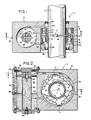
- FIG. 1 is a sectional longitudinal view taken on line 1-1 on FIG. 2 of the novel lubricating system for a uni-directional shaft supported by a pair of non-friction bearings and including an oil reservoir in the bearing casing;
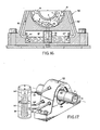
- FIG. 2 is a sectional elevational view taken on line 2-2 of FIG. 1;
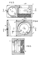
- FIG. 3 is a sectional view of the bearing casing taken on line 3-3 of FIG. 4;
- FIGS. 4 and 5 are sectional views taken on lines 4-4 and 5-5 of FIG. 3, respectively;
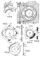
- FIG. 6 is a front elevational view of one embodiment of the lubricant pumper element which is mounted on the shaft of the lubricating system of FIGS. 1-2;
- FIG. 7 is a sectional view taken on line 7-7 of FIG. 6;
- FIG. 8 is an enlarged view of the region near the discharge outlet from the eccentric expander channel operatively associated with the pumper element of FIG. 6;
- FIG. 9 is a front elevational view of another embodiment of the pumper element;
- FIG. 10 is a sectional view taken on line 10-10 of FIG. 9;
- FIG. 11 is a front elevational view of yet another pumper element embodiment;
- FIG. 12 is a sectional view taken on line 12-12 of FIG. 11;
- FIG. 13 is an elevational sectional view of another embodiment of the lubricating system of FIGS. 1- 2 but for a bi-directional shaft;
- FIG. 14 is an elevational sectional view similar to FIG. 13 but wherein the oil reservoir is situated above the bearings;
- FIG. 15 is a sectional longitudinal view taken on line 15-15 of FIG. 14;
- FIG. 16 is an elevational sectional view similar to FIG. 14 but wherein the oil reservoir is situated below the bearings;
- FIG. 17 is a perspective view of the lubricating system of FIG. 2 wherein the oil reservoir is situated outside of the bearing casing;
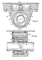
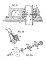
- FIG. 18 is a sectional elevational view of another embodiment of the lubricating system of FIGS. 1-2 but for a vertical shaft;
- FIG. 19 is a perspective view of the novel lubricating bearing system of FIG. 14 used with a concrete saw; and
- FIG. 20 is an exploded view of the arbor shaft assembly in the concrete saw of FIG. 19.
- In the drawings, similar or symmetrical parts will sometimes be designated with the same reference characters followed by a prime (′) and such parts will not be repetitively described.
- One embodiment of the self-lubricating bearing system of this invention, generally designated as 1 (FIGS.1-5), is entirely enclosed in a
unitary casing 2 having amain bore 3 and a longitudinal axis 5 (FIG.4). -
Bore 3 houses ahorizontal sleeve shaft 4 whose axis of rotation is coaxial with the bore's main axis 5 (FIGS. 1-2). Shaft 4 is supported for rotation by a pair ofsuitable bearings elements 7 that rotate between aninner race 9 secured toshaft 4 and a stationaryouter race 10 that abuts against ashoulder 11 inbore 3.Bearing elements 7 can be tapered or cylindrical rollers, balls, etc. - Between
bearings bore 3 is formed anannular well 13 which, in use, accumulates at its bottom a liquid lubricant typically oil of the type that can maintain metal wear particles in suspension. - A circular pumper element, generally designated as P, is concentrically mounted within well 13 on
shaft 4 betweenbearings bearings - In system 1, pumper element P is a vane-type disc concentrically mounted on
shaft 4 and having an outer diameter which corresponds to the diameter ofouter race 10. Pumper element P includes an annular hub 15 (FIGS. 6-8) and four radial vanes generally designated as 17. - The number and shape of
vanes 17 will depend mostly on the speed and lubrication requirements ofbearings vanes 17 could be sufficient, while eight or more such vanes can be used for lower speeds. - Because the shaft's speed is the most important factor, for very high speeds pumper element P can be even reduced to an annular disc 43 (FIGS. 9-10) having an outwardly flared cross-section. Pumper element P can also have a
hub 16′ (FIGS. 11-12) carrying aclip 12 filled withbristles 8 forming anannular brush 43′. - Each
vane 17 has an outwardly-flared end 18 (FIGS. 6-7) having a peripheralarcuate rim 19 andopposite sides consecutive vanes 17 defines apocket 22 therebetween. - Preferably an off-center, circumferential expander channel 24 (FIGS. 2-5), which extends into wall 23 (FIG. 3) of
bore 3, is operatively associated with pumper element P. Channel 24 originates at a point 25 (FIG. 4) and gradually shifts circumferentially off-center over an arcuate extent, say 180°. Thedischarge outlet 26 fromexpander 24 is coupled to and smoothly merges with an anoil return passage 32. - One end 28 (FIG. 1) of
main bore 3 accepts atorque nut 29 for adjusting the axial pressure against bearing 6′ asrollers 7 wear. Bore 3 is effectively sealed against the environment by double-lip seals - Inside
casing 2 is formed an oil reservoir 35 (FIGS. 1-2) containing afilter element 36. The oil inreservoir 35 is cooled byoutside fins 41. Oil can be added through afill plug 39. Adrain plug 40 carries amagnet 42 for attracting most metal wear particles flowing throughfilter 36. - Oil flows from
return passage 32 through a guide generally designated as 34, having four inwardly taperingpassages 34′ that direct the returning oil intofilter element 36 through atube 44. - Clean oil in
reservoir 35 must have a sufficient volume to meet the lubrication needs of system 1. This volume is inversely proportional to the shaft's speed. Either too much or not enough oil inreservoir 35 may result in a shortened bearing life. - The direction of rotation of pumper element P and of the oil flow are indicated in the drawings by the solid arrows. The dotted arrows assume a reversal of rotation and oil flow (FIGS. 13-14).
- In operation of system 1 described so far, the filtered and cooled oil flows out by gravity from
reservoir 35 throughoutlet passages inlet ports casing 2, respectively (FIG. 1). The oil collects at the bottom of well 13 (FIG. 2) and around thelowermost rollers 7 until the oil levels in well 13 and inreservoir 35 equalize. - In each embodiment of pumper element P, its outer periphery rotates opposite to expander
channel 24. - The oil in well 13 starts to rotate under the influence of pumper element P. The pressure starts rising when the oil is forced to enter into the reduced
area 25 of off-center expander 24. Eachvane 17 centrifugally injects a portion of the oil from well 13 intoexpander channel 24, while some of the rotating oil is trapped within pockets 22. The oil acquires kinetic energy withinexpander channel 24 from which it flows out throughdischarge outlet 26 intoreturn passage 32. Whenshaft 4 reaches a constant speed, oil is also fed at a constant rate into well 13. - The velocity of the oil at
discharge outlet 26 must be sufficiently high so as to maintain an adequate oil flow in a generally axial direction across rollers 7 (FIG. 1) and, in so doing, cleansing, cooling and lubricating thebearings - The velocity of the oil flowing through off-
center expander 24 varies depending on the size and shape ofvanes 17, on the arcuate length and eccentricity ofexpander channel 24, on the speed ofshaft 4, and on the dimensions in and arounddischarge outlet 26. Accordingly, the velocity of the oil inexpander 24 can be controlled by (1) changing the eccentricity ofexpander 24, (2) by modifying the design ofvanes 17, (3) by altering the critical dimensions in and aroundoutlet 26, and/or by changing the spacing between the peripheral edge of pumper element P andwall 23 ofbore 3. Interchangeable pumper elements P can be provided having different geometrical configurations. They can be conveniently used to vary in the field the rate of oil flow inexpander channel 24, which is an important advantage of the novel lubricating system 1. - As thus far described,
shaft 4 was assumed to rotate in a single direction, say counterclockwise. - In FIG. 13 is shown a
bi-directional system 50 having a pair of oppositely-directed,eccentric expander channels return passages uni-directional check valves cross-linking channel 54.Expanders - When
shaft 4 rotates counterclockwise, oil pressure inpassage 52 opensvalve 53, whilevalve 53′ remains closed. Oil returns toreservoir 35 only throughexpander 51. Conversely, whenshaft 4 rotates clockwise, oil pressure inpassage 52′ opensvalve 53′, whilevalve 53 remains closed. Oil returns toreservoir 35 only throughexpander 51′ and throughchannel 54. - An important and surprising advantage of system 1 is that it will continue to operate properly even when casing 2 is rotated 90° (not shown) from its position shown in FIGS. 2 and 13 so that
shaft 4 will be supported bybearings - In FIGS. 14-15 is shown another
bi-directional lubricating system 56 also having a pair of oppositely directedexpander channels return passages flappy door valves shaft 4 rotates counterclockwise, oil pressure inpassage 52 opensvalve 57 and closesvalve 57′. Oil returns toreservoir 37 only from and throughexpander channel 51 andvalve 57. Conversely, whenshaft 4 rotates clockwise, oil pressure inpassage 52′ opensvalve 57′ and closesvalve 57. Oil returns toreservoir 37 only from and throughexpander channel 51′ andvalve 57′. - In FIG. 14
reservoir 37 is abovecasing 2 so that oil fromreservoir 37 can flow by gravity into well 13 from which it is sucked out by the rotating pumper element P. - FIG. 16 shows another
bi-directional lubricating system 60, similar tosystem 56, having a pair ofreturn passages flappy door valves - When
shaft 4 rotates counterclockwise, oil pressure inpassages 52 will openvalve 57 andclose valve 57′. In this manner, oil will return toreservoir 37 only from and throughpassage 52 andvalve 57. Conversely, whenshaft 4 rotates clockwise, oil pressure inpassage 52′ will openvalve 57′ andclose valve 57. In this manner, oil will return toreservoir 37 only from and throughpassage 52 andvalve 57. The oil flow acrossbearings tubes 45 positioned between the bottom offilter 36 and the rear sides ofbearings - Because
shaft 4 is abovereservoir 37, oil inpassages lowermost rollers 7 whenshaft 4 is not rotating. Upon rotation ofshaft 4, oil quickly fills up well 13 by suction. Thereafter, normal oil circulation takes place, and the oil level inreservoir 37 drops to a level as shown in FIG. 16. - In the embodiments of the invention thus far described,
reservoirs casing 2. In the modifiedsystem 62 of FIG. 17,reservoir 37 is detached fromcasing 2. Adischarge conduit 63 returns oil toreservoir 37 via aflow guide 34′, whileconduits casing 2. However, in most cases it is more advantageous for the reservoir to be insidecasing 2. - All prior embodiments assumed a horizontal shaft, in system 66 (FIG. 18)
bearings vertical shaft 4, andreservoir 37 is situated such as towet rollers 7 ofbearing 6 but notrollers 7 of bearing 6′. Asshaft 4 starts to rotate, oil fromreservoir 37 is sucked intoexpander 24 and then oil circulation can take place acrossbearings system 66 operates as the previously described lubricating systems. - In FIGS. 19 and 20 is shown a conventional concrete cutting saw 70. Its
diamond blade 71 receives cooling water (not shown) on the opposite sides thereof within a very dirty and corrosive surrounding environment. Acollar 73mounts blade 71 onarbor shaft 72 supported bybearings Bearings Blade 71 must be kept at peak performance to ensure dynamic balance. Its linear speed must not exceed about 3,000 meters/minute, otherwise water will be centrifugally removed from its surfaces. - Such a concrete cutting saw 70 now uses grease and requires daily bearing lubrication, otherwise moisture and debris will set in over night causing rust spots and damage to such bearings. The bearings' single lip seals (not shown) must open to allow for the dirty grease to discharge. As a result, foreign matter and water become inevitably sucked into the bearings.
- The novel lubricating systems of the invention allow the user to periodically schedule service for
bearings lip seals - It will be appreciated that the self-lubricating bearing systems of the invention are simple in construction and economical to manufacture. A film of clean oil is continuously maintained on
rollers 7, moisture and foreign matter are prevented from being sucked into the bearings, heat is removed continuously from the oil, and friction is kept to a minimum between the bearing surfaces, thereby increasing their operational life.
Claims (18)
Applications Claiming Priority (2)
| Application Number | Priority Date | Filing Date | Title |
|---|---|---|---|
| US81850386A | 1986-01-13 | 1986-01-13 | |
| US818503 | 1986-01-13 |
Publications (3)
| Publication Number | Publication Date |
|---|---|
| EP0232978A2 true EP0232978A2 (en) | 1987-08-19 |
| EP0232978A3 EP0232978A3 (en) | 1988-01-07 |
| EP0232978B1 EP0232978B1 (en) | 1993-09-22 |
Family
ID=25225690
Family Applications (1)
| Application Number | Title | Priority Date | Filing Date |
|---|---|---|---|
| EP87300230A Expired - Lifetime EP0232978B1 (en) | 1986-01-13 | 1987-01-12 | Liquid self-lubricating bearing system |
Country Status (6)
| Country | Link |
|---|---|
| EP (1) | EP0232978B1 (en) |
| JP (1) | JPS62167999A (en) |
| AU (1) | AU595572B2 (en) |
| CA (1) | CA1290708C (en) |
| DE (1) | DE3787478T2 (en) |
| MX (1) | MX161223A (en) |
Cited By (8)
| Publication number | Priority date | Publication date | Assignee | Title |
|---|---|---|---|---|
| US5116145A (en) * | 1989-09-25 | 1992-05-26 | Skf Industrial Trading And Developement Company Bv | Roller bearing containing a lubrication pump |
| US5724934A (en) * | 1993-10-26 | 1998-03-10 | Faraci; John A. | Modular rotary engine, and oil slinger and race seal subassemblies thereof |
| DE102006033555A1 (en) * | 2006-07-20 | 2008-01-24 | Deutz Ag | Roller bearing with associated oil filter for e.g. automotive applications, agricultural machinery, marine diesel engines |
| WO2009004378A2 (en) * | 2007-07-02 | 2009-01-08 | Edwards Limited | Vacuum pump |
| WO2018222280A1 (en) * | 2017-05-30 | 2018-12-06 | Itt Manufacturing Enterprises Llc | Oil filter/liquid indicator assembly |
| CN109780060A (en) * | 2019-03-27 | 2019-05-21 | 河北工业大学 | A kind of sliding bearing bearing radial and axial power and changeable axial oil pressure |
| WO2021158231A1 (en) | 2020-02-07 | 2021-08-12 | Itt Manufacturing Enterprises Llc | Two-piece oil filter assembly for pumps |
| CN113418127A (en) * | 2021-06-29 | 2021-09-21 | 胡素珍 | Self-lubricating device based on large-scale mining equipment |
Families Citing this family (1)
| Publication number | Priority date | Publication date | Assignee | Title |
|---|---|---|---|---|
| DE102004053079B3 (en) * | 2004-11-03 | 2006-08-03 | Ab Skf | Bearing arrangement has two tapered roller bearings positioned in O-arrangement and fluid connection is made by drilling section that is parallel to axis of bearing and extends from axial final area of one bearing to other bearing |
Citations (7)
| Publication number | Priority date | Publication date | Assignee | Title |
|---|---|---|---|---|
| BE631886A (en) * | ||||
| FR328E (en) * | 1901-12-05 | 1902-12-11 | Potel Henry Firmin Eugene | A roller lubricator |
| DE579061C (en) * | 1931-04-08 | 1933-06-21 | Buckau Wolf Maschf R | Lubricating device for lamellar safety sliding clutch |
| DE836131C (en) * | 1949-08-19 | 1952-04-10 | Canadian Patents Dev | Lubricating device for the shaft bearings of high-speed rotating engines with a compressor |
| US2950943A (en) * | 1957-06-21 | 1960-08-30 | Allis Chalmers Mfg Co | Lubrication device for antifriction bearings |
| DE1139705B (en) * | 1960-02-25 | 1962-11-15 | Licentia Gmbh | Grease lubrication with grease volume regulator |
| GB2084652A (en) * | 1980-09-29 | 1982-04-15 | Riv Officine Di Villar Perosa | A rotating and pumping unit operable both for supporting a rotary member and for feeding a liquid |
-
1986
- 1986-12-23 CA CA000526125A patent/CA1290708C/en not_active Expired - Lifetime
-
1987
- 1987-01-06 AU AU67178/87A patent/AU595572B2/en not_active Ceased
- 1987-01-12 EP EP87300230A patent/EP0232978B1/en not_active Expired - Lifetime
- 1987-01-12 DE DE3787478T patent/DE3787478T2/en not_active Expired - Fee Related
- 1987-01-12 JP JP62005868A patent/JPS62167999A/en active Pending
- 1987-01-13 MX MX4932A patent/MX161223A/en unknown
Patent Citations (7)
| Publication number | Priority date | Publication date | Assignee | Title |
|---|---|---|---|---|
| BE631886A (en) * | ||||
| FR328E (en) * | 1901-12-05 | 1902-12-11 | Potel Henry Firmin Eugene | A roller lubricator |
| DE579061C (en) * | 1931-04-08 | 1933-06-21 | Buckau Wolf Maschf R | Lubricating device for lamellar safety sliding clutch |
| DE836131C (en) * | 1949-08-19 | 1952-04-10 | Canadian Patents Dev | Lubricating device for the shaft bearings of high-speed rotating engines with a compressor |
| US2950943A (en) * | 1957-06-21 | 1960-08-30 | Allis Chalmers Mfg Co | Lubrication device for antifriction bearings |
| DE1139705B (en) * | 1960-02-25 | 1962-11-15 | Licentia Gmbh | Grease lubrication with grease volume regulator |
| GB2084652A (en) * | 1980-09-29 | 1982-04-15 | Riv Officine Di Villar Perosa | A rotating and pumping unit operable both for supporting a rotary member and for feeding a liquid |
Cited By (13)
| Publication number | Priority date | Publication date | Assignee | Title |
|---|---|---|---|---|
| US5116145A (en) * | 1989-09-25 | 1992-05-26 | Skf Industrial Trading And Developement Company Bv | Roller bearing containing a lubrication pump |
| US5724934A (en) * | 1993-10-26 | 1998-03-10 | Faraci; John A. | Modular rotary engine, and oil slinger and race seal subassemblies thereof |
| DE102006033555A1 (en) * | 2006-07-20 | 2008-01-24 | Deutz Ag | Roller bearing with associated oil filter for e.g. automotive applications, agricultural machinery, marine diesel engines |
| WO2009004378A2 (en) * | 2007-07-02 | 2009-01-08 | Edwards Limited | Vacuum pump |
| WO2009004378A3 (en) * | 2007-07-02 | 2009-05-28 | Edwards Ltd | Vacuum pump |
| US9046103B2 (en) | 2007-07-02 | 2015-06-02 | Edwards Limited | Vacuum pump |
| WO2018222280A1 (en) * | 2017-05-30 | 2018-12-06 | Itt Manufacturing Enterprises Llc | Oil filter/liquid indicator assembly |
| US10648509B2 (en) | 2017-05-30 | 2020-05-12 | Itt Manufacturing Enterprises Llc. | Oil filter/liquid indicator assembly |
| US11111959B2 (en) | 2017-05-30 | 2021-09-07 | Itt Manufacturing Enterprises Llc | Oil filter/liquid indicator assembly |
| CN109780060A (en) * | 2019-03-27 | 2019-05-21 | 河北工业大学 | A kind of sliding bearing bearing radial and axial power and changeable axial oil pressure |
| WO2021158231A1 (en) | 2020-02-07 | 2021-08-12 | Itt Manufacturing Enterprises Llc | Two-piece oil filter assembly for pumps |
| EP4100657A4 (en) * | 2020-02-07 | 2023-11-01 | ITT Manufacturing Enterprises LLC | Two-piece oil filter assembly for pumps |
| CN113418127A (en) * | 2021-06-29 | 2021-09-21 | 胡素珍 | Self-lubricating device based on large-scale mining equipment |
Also Published As
| Publication number | Publication date |
|---|---|
| MX161223A (en) | 1990-08-21 |
| DE3787478D1 (en) | 1993-10-28 |
| DE3787478T2 (en) | 1994-06-16 |
| EP0232978B1 (en) | 1993-09-22 |
| AU595572B2 (en) | 1990-04-05 |
| JPS62167999A (en) | 1987-07-24 |
| EP0232978A3 (en) | 1988-01-07 |
| CA1290708C (en) | 1991-10-15 |
| AU6717887A (en) | 1987-07-16 |
Similar Documents
| Publication | Publication Date | Title |
|---|---|---|
| US5150975A (en) | Compact self-lubricating bearing system | |
| US5150769A (en) | Controlled-flow lubricating system | |
| US8465207B2 (en) | Auxiliary bearing system with oil reservoir for magnetically supported rotor system | |
| KR930021916A (en) | Lubricator for tandem axle unit | |
| JPH03223574A (en) | Seal device and sealing method | |
| US6460656B1 (en) | Dilating lubricant flinger | |
| JP2001513175A (en) | Constant flow cascade lubricator | |
| AU595572B2 (en) | Self-lubricating and self-cleansing bearings | |
| EP0708291A1 (en) | Pump oil mister with reduced windage | |
| US4488855A (en) | Main bearing lubrication system for scroll machine | |
| US6551055B2 (en) | Centrifugal pump having oil misting system with pivoting blades | |
| FR2444224A1 (en) | ||
| JP3471071B2 (en) | Bearing lubrication system for rotating machinery | |
| US6913438B2 (en) | Pump lubrication system including an external reservoir | |
| RU2594922C2 (en) | Neck seal for hydrostatic bearing rolling mill with spaced-apart blades for movement of oil coming from bearing sleeve and bearing insert | |
| CN109863333B (en) | Flow guide for guiding lubricant to supply it to hollow shaft of gearbox | |
| US4403927A (en) | Lubricant distribution system for scroll machine | |
| US4597679A (en) | Apparatus for lubricating a bearing assembly | |
| JP2003526305A (en) | Improved bearing insulation | |
| EP0073281B1 (en) | Bearing | |
| JPH0578691B2 (en) | ||
| US20220333647A1 (en) | Sealing device for pillow blocks | |
| US1914891A (en) | Sealing device | |
| RU2161730C2 (en) | Hydraulic-turbine generator | |
| JPH0521638Y2 (en) |
Legal Events
| Date | Code | Title | Description |
|---|---|---|---|
| PUAI | Public reference made under article 153(3) epc to a published international application that has entered the european phase |
Free format text: ORIGINAL CODE: 0009012 |
|
| AK | Designated contracting states |
Kind code of ref document: A2 Designated state(s): CH DE FR GB IT LI SE |
|
| PUAL | Search report despatched |
Free format text: ORIGINAL CODE: 0009013 |
|
| AK | Designated contracting states |
Kind code of ref document: A3 Designated state(s): CH DE FR GB IT LI SE |
|
| 17P | Request for examination filed |
Effective date: 19880623 |
|
| 17Q | First examination report despatched |
Effective date: 19890714 |
|
| GRAA | (expected) grant |
Free format text: ORIGINAL CODE: 0009210 |
|
| AK | Designated contracting states |
Kind code of ref document: B1 Designated state(s): CH DE FR GB IT LI SE |
|
| REF | Corresponds to: |
Ref document number: 3787478 Country of ref document: DE Date of ref document: 19931028 |
|
| ITF | It: translation for a ep patent filed |
Owner name: SOCIETA' ITALIANA BREVETTI S.P.A. |
|
| ET | Fr: translation filed | ||
| PLBE | No opposition filed within time limit |
Free format text: ORIGINAL CODE: 0009261 |
|
| STAA | Information on the status of an ep patent application or granted ep patent |
Free format text: STATUS: NO OPPOSITION FILED WITHIN TIME LIMIT |
|
| 26N | No opposition filed | ||
| EAL | Se: european patent in force in sweden |
Ref document number: 87300230.7 |
|
| PGFP | Annual fee paid to national office [announced via postgrant information from national office to epo] |
Ref country code: DE Payment date: 19991231 Year of fee payment: 14 |
|
| PGFP | Annual fee paid to national office [announced via postgrant information from national office to epo] |
Ref country code: SE Payment date: 20000107 Year of fee payment: 14 |
|
| PGFP | Annual fee paid to national office [announced via postgrant information from national office to epo] |
Ref country code: CH Payment date: 20000110 Year of fee payment: 14 |
|
| PGFP | Annual fee paid to national office [announced via postgrant information from national office to epo] |
Ref country code: GB Payment date: 20000112 Year of fee payment: 14 Ref country code: FR Payment date: 20000112 Year of fee payment: 14 |
|
| PG25 | Lapsed in a contracting state [announced via postgrant information from national office to epo] |
Ref country code: GB Free format text: LAPSE BECAUSE OF NON-PAYMENT OF DUE FEES Effective date: 20010112 |
|
| PG25 | Lapsed in a contracting state [announced via postgrant information from national office to epo] |
Ref country code: SE Free format text: LAPSE BECAUSE OF NON-PAYMENT OF DUE FEES Effective date: 20010113 |
|
| PG25 | Lapsed in a contracting state [announced via postgrant information from national office to epo] |
Ref country code: LI Free format text: LAPSE BECAUSE OF NON-PAYMENT OF DUE FEES Effective date: 20010131 Ref country code: CH Free format text: LAPSE BECAUSE OF NON-PAYMENT OF DUE FEES Effective date: 20010131 |
|
| GBPC | Gb: european patent ceased through non-payment of renewal fee |
Effective date: 20010112 |
|
| EUG | Se: european patent has lapsed |
Ref document number: 87300230.7 |
|
| REG | Reference to a national code |
Ref country code: CH Ref legal event code: PL |
|
| PG25 | Lapsed in a contracting state [announced via postgrant information from national office to epo] |
Ref country code: FR Free format text: LAPSE BECAUSE OF NON-PAYMENT OF DUE FEES Effective date: 20010928 |
|
| PG25 | Lapsed in a contracting state [announced via postgrant information from national office to epo] |
Ref country code: DE Free format text: LAPSE BECAUSE OF NON-PAYMENT OF DUE FEES Effective date: 20011101 |
|
| REG | Reference to a national code |
Ref country code: FR Ref legal event code: ST |
|
| PG25 | Lapsed in a contracting state [announced via postgrant information from national office to epo] |
Ref country code: IT Free format text: LAPSE BECAUSE OF NON-PAYMENT OF DUE FEES Effective date: 20050112 |