EP0232426A1 - Oxygen gas production unit - Google Patents
Oxygen gas production unit Download PDFInfo
- Publication number
- EP0232426A1 EP0232426A1 EP86904928A EP86904928A EP0232426A1 EP 0232426 A1 EP0232426 A1 EP 0232426A1 EP 86904928 A EP86904928 A EP 86904928A EP 86904928 A EP86904928 A EP 86904928A EP 0232426 A1 EP0232426 A1 EP 0232426A1
- Authority
- EP
- European Patent Office
- Prior art keywords
- oxygen
- air
- liquid
- liquid oxygen
- gas
- Prior art date
- Legal status (The legal status is an assumption and is not a legal conclusion. Google has not performed a legal analysis and makes no representation as to the accuracy of the status listed.)
- Granted
Links
Images



Classifications
-
- F—MECHANICAL ENGINEERING; LIGHTING; HEATING; WEAPONS; BLASTING
- F25—REFRIGERATION OR COOLING; COMBINED HEATING AND REFRIGERATION SYSTEMS; HEAT PUMP SYSTEMS; MANUFACTURE OR STORAGE OF ICE; LIQUEFACTION SOLIDIFICATION OF GASES
- F25J—LIQUEFACTION, SOLIDIFICATION OR SEPARATION OF GASES OR GASEOUS OR LIQUEFIED GASEOUS MIXTURES BY PRESSURE AND COLD TREATMENT OR BY BRINGING THEM INTO THE SUPERCRITICAL STATE
- F25J3/00—Processes or apparatus for separating the constituents of gaseous or liquefied gaseous mixtures involving the use of liquefaction or solidification
- F25J3/02—Processes or apparatus for separating the constituents of gaseous or liquefied gaseous mixtures involving the use of liquefaction or solidification by rectification, i.e. by continuous interchange of heat and material between a vapour stream and a liquid stream
- F25J3/04—Processes or apparatus for separating the constituents of gaseous or liquefied gaseous mixtures involving the use of liquefaction or solidification by rectification, i.e. by continuous interchange of heat and material between a vapour stream and a liquid stream for air
- F25J3/04151—Purification and (pre-)cooling of the feed air; recuperative heat-exchange with product streams
- F25J3/04163—Hot end purification of the feed air
- F25J3/04169—Hot end purification of the feed air by adsorption of the impurities
- F25J3/04181—Regenerating the adsorbents
-
- F—MECHANICAL ENGINEERING; LIGHTING; HEATING; WEAPONS; BLASTING
- F25—REFRIGERATION OR COOLING; COMBINED HEATING AND REFRIGERATION SYSTEMS; HEAT PUMP SYSTEMS; MANUFACTURE OR STORAGE OF ICE; LIQUEFACTION SOLIDIFICATION OF GASES
- F25J—LIQUEFACTION, SOLIDIFICATION OR SEPARATION OF GASES OR GASEOUS OR LIQUEFIED GASEOUS MIXTURES BY PRESSURE AND COLD TREATMENT OR BY BRINGING THEM INTO THE SUPERCRITICAL STATE
- F25J3/00—Processes or apparatus for separating the constituents of gaseous or liquefied gaseous mixtures involving the use of liquefaction or solidification
- F25J3/02—Processes or apparatus for separating the constituents of gaseous or liquefied gaseous mixtures involving the use of liquefaction or solidification by rectification, i.e. by continuous interchange of heat and material between a vapour stream and a liquid stream
- F25J3/04—Processes or apparatus for separating the constituents of gaseous or liquefied gaseous mixtures involving the use of liquefaction or solidification by rectification, i.e. by continuous interchange of heat and material between a vapour stream and a liquid stream for air
- F25J3/04006—Providing pressurised feed air or process streams within or from the air fractionation unit
- F25J3/04012—Providing pressurised feed air or process streams within or from the air fractionation unit by compression of warm gaseous streams; details of intake or interstage cooling
- F25J3/04018—Providing pressurised feed air or process streams within or from the air fractionation unit by compression of warm gaseous streams; details of intake or interstage cooling of main feed air
-
- F—MECHANICAL ENGINEERING; LIGHTING; HEATING; WEAPONS; BLASTING
- F25—REFRIGERATION OR COOLING; COMBINED HEATING AND REFRIGERATION SYSTEMS; HEAT PUMP SYSTEMS; MANUFACTURE OR STORAGE OF ICE; LIQUEFACTION SOLIDIFICATION OF GASES
- F25J—LIQUEFACTION, SOLIDIFICATION OR SEPARATION OF GASES OR GASEOUS OR LIQUEFIED GASEOUS MIXTURES BY PRESSURE AND COLD TREATMENT OR BY BRINGING THEM INTO THE SUPERCRITICAL STATE
- F25J3/00—Processes or apparatus for separating the constituents of gaseous or liquefied gaseous mixtures involving the use of liquefaction or solidification
- F25J3/02—Processes or apparatus for separating the constituents of gaseous or liquefied gaseous mixtures involving the use of liquefaction or solidification by rectification, i.e. by continuous interchange of heat and material between a vapour stream and a liquid stream
- F25J3/04—Processes or apparatus for separating the constituents of gaseous or liquefied gaseous mixtures involving the use of liquefaction or solidification by rectification, i.e. by continuous interchange of heat and material between a vapour stream and a liquid stream for air
- F25J3/04006—Providing pressurised feed air or process streams within or from the air fractionation unit
- F25J3/04078—Providing pressurised feed air or process streams within or from the air fractionation unit providing pressurized products by liquid compression and vaporisation with cold recovery, i.e. so-called internal compression
- F25J3/0409—Providing pressurised feed air or process streams within or from the air fractionation unit providing pressurized products by liquid compression and vaporisation with cold recovery, i.e. so-called internal compression of oxygen
-
- F—MECHANICAL ENGINEERING; LIGHTING; HEATING; WEAPONS; BLASTING
- F25—REFRIGERATION OR COOLING; COMBINED HEATING AND REFRIGERATION SYSTEMS; HEAT PUMP SYSTEMS; MANUFACTURE OR STORAGE OF ICE; LIQUEFACTION SOLIDIFICATION OF GASES
- F25J—LIQUEFACTION, SOLIDIFICATION OR SEPARATION OF GASES OR GASEOUS OR LIQUEFIED GASEOUS MIXTURES BY PRESSURE AND COLD TREATMENT OR BY BRINGING THEM INTO THE SUPERCRITICAL STATE
- F25J3/00—Processes or apparatus for separating the constituents of gaseous or liquefied gaseous mixtures involving the use of liquefaction or solidification
- F25J3/02—Processes or apparatus for separating the constituents of gaseous or liquefied gaseous mixtures involving the use of liquefaction or solidification by rectification, i.e. by continuous interchange of heat and material between a vapour stream and a liquid stream
- F25J3/04—Processes or apparatus for separating the constituents of gaseous or liquefied gaseous mixtures involving the use of liquefaction or solidification by rectification, i.e. by continuous interchange of heat and material between a vapour stream and a liquid stream for air
- F25J3/04151—Purification and (pre-)cooling of the feed air; recuperative heat-exchange with product streams
- F25J3/04157—Afterstage cooling and so-called "pre-cooling" of the feed air upstream the air purification unit and main heat exchange line
-
- F—MECHANICAL ENGINEERING; LIGHTING; HEATING; WEAPONS; BLASTING
- F25—REFRIGERATION OR COOLING; COMBINED HEATING AND REFRIGERATION SYSTEMS; HEAT PUMP SYSTEMS; MANUFACTURE OR STORAGE OF ICE; LIQUEFACTION SOLIDIFICATION OF GASES
- F25J—LIQUEFACTION, SOLIDIFICATION OR SEPARATION OF GASES OR GASEOUS OR LIQUEFIED GASEOUS MIXTURES BY PRESSURE AND COLD TREATMENT OR BY BRINGING THEM INTO THE SUPERCRITICAL STATE
- F25J3/00—Processes or apparatus for separating the constituents of gaseous or liquefied gaseous mixtures involving the use of liquefaction or solidification
- F25J3/02—Processes or apparatus for separating the constituents of gaseous or liquefied gaseous mixtures involving the use of liquefaction or solidification by rectification, i.e. by continuous interchange of heat and material between a vapour stream and a liquid stream
- F25J3/04—Processes or apparatus for separating the constituents of gaseous or liquefied gaseous mixtures involving the use of liquefaction or solidification by rectification, i.e. by continuous interchange of heat and material between a vapour stream and a liquid stream for air
- F25J3/04151—Purification and (pre-)cooling of the feed air; recuperative heat-exchange with product streams
- F25J3/04187—Cooling of the purified feed air by recuperative heat-exchange; Heat-exchange with product streams
- F25J3/04193—Division of the main heat exchange line in consecutive sections having different functions
- F25J3/04206—Division of the main heat exchange line in consecutive sections having different functions including a so-called "auxiliary vaporiser" for vaporising and producing a gaseous product
- F25J3/04212—Division of the main heat exchange line in consecutive sections having different functions including a so-called "auxiliary vaporiser" for vaporising and producing a gaseous product and simultaneously condensing vapor from a column serving as reflux within the or another column
-
- F—MECHANICAL ENGINEERING; LIGHTING; HEATING; WEAPONS; BLASTING
- F25—REFRIGERATION OR COOLING; COMBINED HEATING AND REFRIGERATION SYSTEMS; HEAT PUMP SYSTEMS; MANUFACTURE OR STORAGE OF ICE; LIQUEFACTION SOLIDIFICATION OF GASES
- F25J—LIQUEFACTION, SOLIDIFICATION OR SEPARATION OF GASES OR GASEOUS OR LIQUEFIED GASEOUS MIXTURES BY PRESSURE AND COLD TREATMENT OR BY BRINGING THEM INTO THE SUPERCRITICAL STATE
- F25J3/00—Processes or apparatus for separating the constituents of gaseous or liquefied gaseous mixtures involving the use of liquefaction or solidification
- F25J3/02—Processes or apparatus for separating the constituents of gaseous or liquefied gaseous mixtures involving the use of liquefaction or solidification by rectification, i.e. by continuous interchange of heat and material between a vapour stream and a liquid stream
- F25J3/04—Processes or apparatus for separating the constituents of gaseous or liquefied gaseous mixtures involving the use of liquefaction or solidification by rectification, i.e. by continuous interchange of heat and material between a vapour stream and a liquid stream for air
- F25J3/04151—Purification and (pre-)cooling of the feed air; recuperative heat-exchange with product streams
- F25J3/04187—Cooling of the purified feed air by recuperative heat-exchange; Heat-exchange with product streams
- F25J3/04218—Parallel arrangement of the main heat exchange line in cores having different functions, e.g. in low pressure and high pressure cores
-
- F—MECHANICAL ENGINEERING; LIGHTING; HEATING; WEAPONS; BLASTING
- F25—REFRIGERATION OR COOLING; COMBINED HEATING AND REFRIGERATION SYSTEMS; HEAT PUMP SYSTEMS; MANUFACTURE OR STORAGE OF ICE; LIQUEFACTION SOLIDIFICATION OF GASES
- F25J—LIQUEFACTION, SOLIDIFICATION OR SEPARATION OF GASES OR GASEOUS OR LIQUEFIED GASEOUS MIXTURES BY PRESSURE AND COLD TREATMENT OR BY BRINGING THEM INTO THE SUPERCRITICAL STATE
- F25J3/00—Processes or apparatus for separating the constituents of gaseous or liquefied gaseous mixtures involving the use of liquefaction or solidification
- F25J3/02—Processes or apparatus for separating the constituents of gaseous or liquefied gaseous mixtures involving the use of liquefaction or solidification by rectification, i.e. by continuous interchange of heat and material between a vapour stream and a liquid stream
- F25J3/04—Processes or apparatus for separating the constituents of gaseous or liquefied gaseous mixtures involving the use of liquefaction or solidification by rectification, i.e. by continuous interchange of heat and material between a vapour stream and a liquid stream for air
- F25J3/04248—Generation of cold for compensating heat leaks or liquid production, e.g. by Joule-Thompson expansion
- F25J3/04254—Generation of cold for compensating heat leaks or liquid production, e.g. by Joule-Thompson expansion using the cold stored in external cryogenic fluids
-
- F—MECHANICAL ENGINEERING; LIGHTING; HEATING; WEAPONS; BLASTING
- F25—REFRIGERATION OR COOLING; COMBINED HEATING AND REFRIGERATION SYSTEMS; HEAT PUMP SYSTEMS; MANUFACTURE OR STORAGE OF ICE; LIQUEFACTION SOLIDIFICATION OF GASES
- F25J—LIQUEFACTION, SOLIDIFICATION OR SEPARATION OF GASES OR GASEOUS OR LIQUEFIED GASEOUS MIXTURES BY PRESSURE AND COLD TREATMENT OR BY BRINGING THEM INTO THE SUPERCRITICAL STATE
- F25J3/00—Processes or apparatus for separating the constituents of gaseous or liquefied gaseous mixtures involving the use of liquefaction or solidification
- F25J3/02—Processes or apparatus for separating the constituents of gaseous or liquefied gaseous mixtures involving the use of liquefaction or solidification by rectification, i.e. by continuous interchange of heat and material between a vapour stream and a liquid stream
- F25J3/04—Processes or apparatus for separating the constituents of gaseous or liquefied gaseous mixtures involving the use of liquefaction or solidification by rectification, i.e. by continuous interchange of heat and material between a vapour stream and a liquid stream for air
- F25J3/04406—Processes or apparatus for separating the constituents of gaseous or liquefied gaseous mixtures involving the use of liquefaction or solidification by rectification, i.e. by continuous interchange of heat and material between a vapour stream and a liquid stream for air using a dual pressure main column system
- F25J3/04412—Processes or apparatus for separating the constituents of gaseous or liquefied gaseous mixtures involving the use of liquefaction or solidification by rectification, i.e. by continuous interchange of heat and material between a vapour stream and a liquid stream for air using a dual pressure main column system in a classical double column flowsheet, i.e. with thermal coupling by a main reboiler-condenser in the bottom of low pressure respectively top of high pressure column
-
- F—MECHANICAL ENGINEERING; LIGHTING; HEATING; WEAPONS; BLASTING
- F25—REFRIGERATION OR COOLING; COMBINED HEATING AND REFRIGERATION SYSTEMS; HEAT PUMP SYSTEMS; MANUFACTURE OR STORAGE OF ICE; LIQUEFACTION SOLIDIFICATION OF GASES
- F25J—LIQUEFACTION, SOLIDIFICATION OR SEPARATION OF GASES OR GASEOUS OR LIQUEFIED GASEOUS MIXTURES BY PRESSURE AND COLD TREATMENT OR BY BRINGING THEM INTO THE SUPERCRITICAL STATE
- F25J3/00—Processes or apparatus for separating the constituents of gaseous or liquefied gaseous mixtures involving the use of liquefaction or solidification
- F25J3/02—Processes or apparatus for separating the constituents of gaseous or liquefied gaseous mixtures involving the use of liquefaction or solidification by rectification, i.e. by continuous interchange of heat and material between a vapour stream and a liquid stream
- F25J3/04—Processes or apparatus for separating the constituents of gaseous or liquefied gaseous mixtures involving the use of liquefaction or solidification by rectification, i.e. by continuous interchange of heat and material between a vapour stream and a liquid stream for air
- F25J3/04636—Processes or apparatus for separating the constituents of gaseous or liquefied gaseous mixtures involving the use of liquefaction or solidification by rectification, i.e. by continuous interchange of heat and material between a vapour stream and a liquid stream for air using a hybrid air separation unit, e.g. combined process by cryogenic separation and non-cryogenic separation techniques
-
- F—MECHANICAL ENGINEERING; LIGHTING; HEATING; WEAPONS; BLASTING
- F25—REFRIGERATION OR COOLING; COMBINED HEATING AND REFRIGERATION SYSTEMS; HEAT PUMP SYSTEMS; MANUFACTURE OR STORAGE OF ICE; LIQUEFACTION SOLIDIFICATION OF GASES
- F25J—LIQUEFACTION, SOLIDIFICATION OR SEPARATION OF GASES OR GASEOUS OR LIQUEFIED GASEOUS MIXTURES BY PRESSURE AND COLD TREATMENT OR BY BRINGING THEM INTO THE SUPERCRITICAL STATE
- F25J3/00—Processes or apparatus for separating the constituents of gaseous or liquefied gaseous mixtures involving the use of liquefaction or solidification
- F25J3/02—Processes or apparatus for separating the constituents of gaseous or liquefied gaseous mixtures involving the use of liquefaction or solidification by rectification, i.e. by continuous interchange of heat and material between a vapour stream and a liquid stream
- F25J3/04—Processes or apparatus for separating the constituents of gaseous or liquefied gaseous mixtures involving the use of liquefaction or solidification by rectification, i.e. by continuous interchange of heat and material between a vapour stream and a liquid stream for air
- F25J3/04763—Start-up or control of the process; Details of the apparatus used
- F25J3/04769—Operation, control and regulation of the process; Instrumentation within the process
- F25J3/04854—Safety aspects of operation
- F25J3/0486—Safety aspects of operation of vaporisers for oxygen enriched liquids, e.g. purging of liquids
-
- F—MECHANICAL ENGINEERING; LIGHTING; HEATING; WEAPONS; BLASTING
- F25—REFRIGERATION OR COOLING; COMBINED HEATING AND REFRIGERATION SYSTEMS; HEAT PUMP SYSTEMS; MANUFACTURE OR STORAGE OF ICE; LIQUEFACTION SOLIDIFICATION OF GASES
- F25J—LIQUEFACTION, SOLIDIFICATION OR SEPARATION OF GASES OR GASEOUS OR LIQUEFIED GASEOUS MIXTURES BY PRESSURE AND COLD TREATMENT OR BY BRINGING THEM INTO THE SUPERCRITICAL STATE
- F25J3/00—Processes or apparatus for separating the constituents of gaseous or liquefied gaseous mixtures involving the use of liquefaction or solidification
- F25J3/02—Processes or apparatus for separating the constituents of gaseous or liquefied gaseous mixtures involving the use of liquefaction or solidification by rectification, i.e. by continuous interchange of heat and material between a vapour stream and a liquid stream
- F25J3/04—Processes or apparatus for separating the constituents of gaseous or liquefied gaseous mixtures involving the use of liquefaction or solidification by rectification, i.e. by continuous interchange of heat and material between a vapour stream and a liquid stream for air
- F25J3/04763—Start-up or control of the process; Details of the apparatus used
- F25J3/04866—Construction and layout of air fractionation equipments, e.g. valves, machines
-
- F—MECHANICAL ENGINEERING; LIGHTING; HEATING; WEAPONS; BLASTING
- F25—REFRIGERATION OR COOLING; COMBINED HEATING AND REFRIGERATION SYSTEMS; HEAT PUMP SYSTEMS; MANUFACTURE OR STORAGE OF ICE; LIQUEFACTION SOLIDIFICATION OF GASES
- F25J—LIQUEFACTION, SOLIDIFICATION OR SEPARATION OF GASES OR GASEOUS OR LIQUEFIED GASEOUS MIXTURES BY PRESSURE AND COLD TREATMENT OR BY BRINGING THEM INTO THE SUPERCRITICAL STATE
- F25J2200/00—Processes or apparatus using separation by rectification
- F25J2200/04—Processes or apparatus using separation by rectification in a dual pressure main column system
- F25J2200/06—Processes or apparatus using separation by rectification in a dual pressure main column system in a classical double column flow-sheet, i.e. with thermal coupling by a main reboiler-condenser in the bottom of low pressure respectively top of high pressure column
-
- F—MECHANICAL ENGINEERING; LIGHTING; HEATING; WEAPONS; BLASTING
- F25—REFRIGERATION OR COOLING; COMBINED HEATING AND REFRIGERATION SYSTEMS; HEAT PUMP SYSTEMS; MANUFACTURE OR STORAGE OF ICE; LIQUEFACTION SOLIDIFICATION OF GASES
- F25J—LIQUEFACTION, SOLIDIFICATION OR SEPARATION OF GASES OR GASEOUS OR LIQUEFIED GASEOUS MIXTURES BY PRESSURE AND COLD TREATMENT OR BY BRINGING THEM INTO THE SUPERCRITICAL STATE
- F25J2205/00—Processes or apparatus using other separation and/or other processing means
- F25J2205/30—Processes or apparatus using other separation and/or other processing means using a washing, e.g. "scrubbing" or bubble column for purification purposes
- F25J2205/32—Processes or apparatus using other separation and/or other processing means using a washing, e.g. "scrubbing" or bubble column for purification purposes as direct contact cooling tower to produce a cooled gas stream, e.g. direct contact after cooler [DCAC]
-
- F—MECHANICAL ENGINEERING; LIGHTING; HEATING; WEAPONS; BLASTING
- F25—REFRIGERATION OR COOLING; COMBINED HEATING AND REFRIGERATION SYSTEMS; HEAT PUMP SYSTEMS; MANUFACTURE OR STORAGE OF ICE; LIQUEFACTION SOLIDIFICATION OF GASES
- F25J—LIQUEFACTION, SOLIDIFICATION OR SEPARATION OF GASES OR GASEOUS OR LIQUEFIED GASEOUS MIXTURES BY PRESSURE AND COLD TREATMENT OR BY BRINGING THEM INTO THE SUPERCRITICAL STATE
- F25J2205/00—Processes or apparatus using other separation and/or other processing means
- F25J2205/30—Processes or apparatus using other separation and/or other processing means using a washing, e.g. "scrubbing" or bubble column for purification purposes
- F25J2205/34—Processes or apparatus using other separation and/or other processing means using a washing, e.g. "scrubbing" or bubble column for purification purposes as evaporative cooling tower to produce chilled water, e.g. evaporative water chiller [EWC]
-
- F—MECHANICAL ENGINEERING; LIGHTING; HEATING; WEAPONS; BLASTING
- F25—REFRIGERATION OR COOLING; COMBINED HEATING AND REFRIGERATION SYSTEMS; HEAT PUMP SYSTEMS; MANUFACTURE OR STORAGE OF ICE; LIQUEFACTION SOLIDIFICATION OF GASES
- F25J—LIQUEFACTION, SOLIDIFICATION OR SEPARATION OF GASES OR GASEOUS OR LIQUEFIED GASEOUS MIXTURES BY PRESSURE AND COLD TREATMENT OR BY BRINGING THEM INTO THE SUPERCRITICAL STATE
- F25J2205/00—Processes or apparatus using other separation and/or other processing means
- F25J2205/60—Processes or apparatus using other separation and/or other processing means using adsorption on solid adsorbents, e.g. by temperature-swing adsorption [TSA] at the hot or cold end
- F25J2205/66—Regenerating the adsorption vessel, e.g. kind of reactivation gas
- F25J2205/70—Heating the adsorption vessel
-
- F—MECHANICAL ENGINEERING; LIGHTING; HEATING; WEAPONS; BLASTING
- F25—REFRIGERATION OR COOLING; COMBINED HEATING AND REFRIGERATION SYSTEMS; HEAT PUMP SYSTEMS; MANUFACTURE OR STORAGE OF ICE; LIQUEFACTION SOLIDIFICATION OF GASES
- F25J—LIQUEFACTION, SOLIDIFICATION OR SEPARATION OF GASES OR GASEOUS OR LIQUEFIED GASEOUS MIXTURES BY PRESSURE AND COLD TREATMENT OR BY BRINGING THEM INTO THE SUPERCRITICAL STATE
- F25J2210/00—Processes characterised by the type or other details of the feed stream
- F25J2210/50—Oxygen
-
- F—MECHANICAL ENGINEERING; LIGHTING; HEATING; WEAPONS; BLASTING
- F25—REFRIGERATION OR COOLING; COMBINED HEATING AND REFRIGERATION SYSTEMS; HEAT PUMP SYSTEMS; MANUFACTURE OR STORAGE OF ICE; LIQUEFACTION SOLIDIFICATION OF GASES
- F25J—LIQUEFACTION, SOLIDIFICATION OR SEPARATION OF GASES OR GASEOUS OR LIQUEFIED GASEOUS MIXTURES BY PRESSURE AND COLD TREATMENT OR BY BRINGING THEM INTO THE SUPERCRITICAL STATE
- F25J2230/00—Processes or apparatus involving steps for increasing the pressure of gaseous process streams
- F25J2230/04—Compressor cooling arrangement, e.g. inter- or after-stage cooling or condensate removal
-
- F—MECHANICAL ENGINEERING; LIGHTING; HEATING; WEAPONS; BLASTING
- F25—REFRIGERATION OR COOLING; COMBINED HEATING AND REFRIGERATION SYSTEMS; HEAT PUMP SYSTEMS; MANUFACTURE OR STORAGE OF ICE; LIQUEFACTION SOLIDIFICATION OF GASES
- F25J—LIQUEFACTION, SOLIDIFICATION OR SEPARATION OF GASES OR GASEOUS OR LIQUEFIED GASEOUS MIXTURES BY PRESSURE AND COLD TREATMENT OR BY BRINGING THEM INTO THE SUPERCRITICAL STATE
- F25J2235/00—Processes or apparatus involving steps for increasing the pressure or for conveying of liquid process streams
- F25J2235/50—Processes or apparatus involving steps for increasing the pressure or for conveying of liquid process streams the fluid being oxygen
-
- F—MECHANICAL ENGINEERING; LIGHTING; HEATING; WEAPONS; BLASTING
- F25—REFRIGERATION OR COOLING; COMBINED HEATING AND REFRIGERATION SYSTEMS; HEAT PUMP SYSTEMS; MANUFACTURE OR STORAGE OF ICE; LIQUEFACTION SOLIDIFICATION OF GASES
- F25J—LIQUEFACTION, SOLIDIFICATION OR SEPARATION OF GASES OR GASEOUS OR LIQUEFIED GASEOUS MIXTURES BY PRESSURE AND COLD TREATMENT OR BY BRINGING THEM INTO THE SUPERCRITICAL STATE
- F25J2250/00—Details related to the use of reboiler-condensers
- F25J2250/30—External or auxiliary boiler-condenser in general, e.g. without a specified fluid or one fluid is not a primary air component or an intermediate fluid
- F25J2250/40—One fluid being air
-
- F—MECHANICAL ENGINEERING; LIGHTING; HEATING; WEAPONS; BLASTING
- F25—REFRIGERATION OR COOLING; COMBINED HEATING AND REFRIGERATION SYSTEMS; HEAT PUMP SYSTEMS; MANUFACTURE OR STORAGE OF ICE; LIQUEFACTION SOLIDIFICATION OF GASES
- F25J—LIQUEFACTION, SOLIDIFICATION OR SEPARATION OF GASES OR GASEOUS OR LIQUEFIED GASEOUS MIXTURES BY PRESSURE AND COLD TREATMENT OR BY BRINGING THEM INTO THE SUPERCRITICAL STATE
- F25J2250/00—Details related to the use of reboiler-condensers
- F25J2250/30—External or auxiliary boiler-condenser in general, e.g. without a specified fluid or one fluid is not a primary air component or an intermediate fluid
- F25J2250/50—One fluid being oxygen
-
- Y—GENERAL TAGGING OF NEW TECHNOLOGICAL DEVELOPMENTS; GENERAL TAGGING OF CROSS-SECTIONAL TECHNOLOGIES SPANNING OVER SEVERAL SECTIONS OF THE IPC; TECHNICAL SUBJECTS COVERED BY FORMER USPC CROSS-REFERENCE ART COLLECTIONS [XRACs] AND DIGESTS
- Y10—TECHNICAL SUBJECTS COVERED BY FORMER USPC
- Y10S—TECHNICAL SUBJECTS COVERED BY FORMER USPC CROSS-REFERENCE ART COLLECTIONS [XRACs] AND DIGESTS
- Y10S62/00—Refrigeration
- Y10S62/912—External refrigeration system
- Y10S62/913—Liquified gas
Definitions
- the present invention relates to an oxygen gas production apparatus which provides high purity gaseous oxygen in pressurized state.
- the present invention is directed to:
- the advantages of the oxygen gas production apparatus include the following. Firstly, because it does not include an expansion turbine but, instead, uses a liquid oxygen storage means, such as a liquid oxygen storage tank, which has no revolving part, the whole equipment is virtually free of operation troubles and failures. Moreover, whereas the expansion turbine is an expensive machine, the liquid oxygen storage tank is available at low cost and does not call for special maintenance personnel.
- the expansion turbine is further disadvantageous in that since it cannot be easily driven to follow variations in load faithfully, i.e. at a varying rotational speed commensurate with the varying rate of withdrawal of product oxygen gas, the compressed air cannot be chilled to a predetermined temperature at all times.
- the apparatus according to the present invention includes a liquid oxygen storage means in lieu of an expansion turbine and uses liquid oxygen which can be supplied at delicately controlled rates as a refrigeration medium so that product oxygen gas of very high purity can be obtained on a constant basis.
- this apparatus is provided with a pressurizing means, the high-purity product oxygen can be made available in pressurized condition which is convenient in use at points of consumption.
- the above principle of pressurizing liquid oxygen results in a remarkable improvement in the efficiency of compression, leading to drastic reductions in oxygen gas production cost and equipment scale.
- the required seal may be less positive, so that it is easier to prevent oxygen leaks. In other words, the leakage of oxygen can be completely inhibited. Therefore, the present invention is a remarkable step forward from the standpoint of prevention of explosion and other hazards as well.
- the apparatus generally comprises a first air compressor 1, a waste heat recovery unit 2, an intercooler 3, a second air compressor 4, an after-cooler 5, and a couple of air cooling columns 6, one of which (6a) is closed with the other (6b) communicating with an exhaust pipe 61.
- the apparatus further comprises a couple of adsorption columns 7, which are packed with molecular sieves and alternately operated to adsorb H 2 0 and C0 2 in the air compressed by said first and second air compressors 1 and 4.
- the reference numeral 8 represents a first heat exchanger which is supplied with the compressed air freed of H 2 0 and C0 2 by said adsorption column 7 via a compressed air supply pipe 9 and by which said compressed air is chilled to a cryogenic temperature.
- the reference numeral 10 represents a second heat exchanger which is supplied with the compressed air freed of H 2 0 and C0 2 ,through a branch pipe 9a branching out from said compressed air supply pipe 9.
- the compressed air fed into this second heat exchanger 10 is also chilled to a cryogenic temperature by heat exchange and, then, converges with the cryogenic compressed air from said first heat exchanger 8.
- the oxygen production apparatus according to this embodiment further includes a fractionation column 11, a bottom column of which is indicated at 12.
- the compressed air chilled to a cryogenic temperature by said first and second heat exchangers 8, 10 and supplied via the pipe 9 is further chilled and a portion thereof is liquefied and pooled in the bottom as liquefied air 13, while nitrogen (containing small amounts of He, etc.) alone being held in gaseous state in the top.
- the reference numeral 15 represents a top column segment of said fractionation column 11 and has a built-in condenser 16.
- This condenser 16 is supplied with a portion of nitrogen gas (containing small amounts of He gas, etc.) pooled in the top of the bottom column segment 12 of said fractionation column 11 via a pipe 12b and the nitrogen gas having a boiling point higher than that of He gas is liquefied and sent to a liquid nitrogen basin 12a in the bottom column segment 12 via a pipe 12c, while the lower-boiling He gas is released as it is into the atmosphere via a pipe 16a.
- nitrogen gas containing small amounts of He gas, etc.
- the inside of said top column segment 15 is maintained in relatively decompressed condition as compared with the inside of said bottom column segment 12, and the liquefied air (50-70% N 2 , 30-50% 0 2 ) 13 pooled in the bottom of said bottom column 12 is introduced into the intermediate segment via a pipe 18 fitted with an expansion valve 17a, whereby its low- boiling fraction nitrogen is gasified and the liquid oxygen 21c collects in the bottom of the column segment 15.
- a portion of liquid nitrogen pooled in the liquid nitrogen basin 12a within the bottom column component 12 is sent to the top column component 15 via a pipe 29 fitted with an expansion valve 29a for use as a reflux fluid in the top column segment 15.
- the reference numeral 30 represents a waste nitrogen gas withdrawal pipe for withdrawing the nitrogen fraction (not so high in purity) collected in the top of the top column segment 15 as waste nitrogen gas.
- This waste nitrogen gas is guided to the first heat exchanger 8 where the material air is chilled by the refrigeration to a cryogenic temperature.
- the nitrogen gas is then guided to the cooling column 6b in the cooling column set 6 via a branch pipe 30a, where it is cooled by showers of water ejected from the tip nozzle of a pipe 34.
- the waste nitrogen gas which has thus undergone heat exchange is released from a pipe 61 into the atmosphere as indicated by arrowmark D. In this connection, a portion of the waste nitrogen gas taken out from the top column segment 15 via the pipe 30.
- the cryogenic waste nitrogen gas is guided from the.pipe 30 to the waste heat recovery unit 2 via a pipe 39 and the resultant nitrogen gas at elevated temperature is fed to a regeneration heater 41 via a pipe 40 to further increase its temperature.
- the heated nitrogen gas is fed to the idle adsorption column for regeneration of its molecular sieve and, then, released into the atmosphere via pipes 61a and 61 as indicated by arrowmark D.
- the above-mentioned molecular sieve is little adsorbent at high temperature but displays a high adsorptive affinity at low temperature. Accordingly the molecular sieve just regenerated as above is so high in temperature that it cannot exhibit its expected adsorptive performance.
- the low- temperature waste nitrogen gas from a pipe 30b is introduced to cool the molecular sieve and the waste nitrogen gas is released into the atmosphere as indicated by arrowmark D.
- the regeneration cycle is thus completed.
- the two adsorption columns 7 are alternately regenerated in the above manner.
- the water 31b cooled by waste nitrogen gas in the cooling column 6b collects in the bottom of the column 6b and is sent by a pump 32 via a pipe 33 into the top of the closed cooling column 6a, where it flows down in the manner of a shower to cool the material air fed from said first and second air compressors 1, 4.
- the water 31a which has completed this cooling operation is returned to the cooling column 6b by the pressure gradient and cooled again by the refrigeration provided by waste nitrogen gas.
- a liquid oxygen via a pipe 23a from a liquid oxygen storage tank 23 which is supplied with liquid oxygen from an external source and stores it, and this liquid oxygen is used to cool the condenser 16 built into the top column segment 15.
- Indicated at 21a is a gaseous oxygen withdrawal pipe for withdrawing the gasified fraction of liquid oxygen 21c pooled in the bottom of the top column segment 15.
- This pipe receives the gaseous oxygen taken at a level slightly above the level of liquid oxygen 21c (purity 99.5%) and transports it to the first heat exchanger 8 where the oxygen gas is adjusted to atmospheric temperature by heat exchange with compressed air feed and sent to the product oxygen withdrawal pipe 21b.
- Indicated at 29c is a disposal pipe for disposing of the liquid oxygen 21c collected in the bottom of the top column segment 15.
- This pipe sends the liquid oxygen 21c to the second heat exchanger 10 where it undergoes heat exchange with material air to chill the latter to a cryogenic temperature, after which it is released as indicated by arrowmark C.
- the reference numeral 24 represents a compression means comprising an oxygen gas compressor disposed in the product oxygen gas withdrawal pipe 21b. This compression means pressurizes the product oxygen gas to a prescribed pressure so that the product oxygen gas may be obtained in pressurized state.
- the reference numeral 44 represents a backup system line which opens a valve 44a in the event of a failure of the air compression system line, whereby the liquid oxygen in the liquid oxygen storage tank 23 is vaporized in an evaporator 45 and sent into the pipe 21b so as to prevent interruption of oxygen gas feed.
- a dot-broken line is a vacuum cold housing which prevents entry of heat from outside for a further improvement of purification efficiency.
- the apparatus described above produces product oxygen gas in pressurized state in the following manner.
- the air is compressed by the air compressor 1 and the resulting heat is recovered by the waste heat recovery unit 2.
- the compressed air is cooled by the intercooler 3, compressed by the air compressor 4, further cooled by the after-cooler 5 and sent to the closed cooling column 6a where it is contacted in counter current with the water cooled by waste nitrogen gas.
- the cooled air is fed to the adsorption column 7 wherein H 2 0 and C0 2 are adsorbed and removed.
- a portion of the compressed air freed of H20 and C0 2 is fed via the pipe ' 9 into the first heat exchanger 8 where it is chilled to a cryogenic temperature, while the remainder is fed via the branch pipe 9a into the second heat exchanger 10 where it is chilled to a cryogenic temperature.
- the two cryogenic air streams are combined and fed into the bottom of the bottom column segment 12.
- This compressed air is distilled by counter-current contact with overflowing liquid nitrogen from the liquid nitrogen basin 12a to liquefy the oxygen fraction and pool it in the bottom of the bottom column segment 12.
- oxygen boils at -183°C and nitrogen boils at -196°C the higher-boiling oxygen fraction of the compressed air is liquefied, while the nitrogen fraction remains gaseous. Accordingly the oxygen-rich liquefied air 13 collects in the bottom of the bottom column segment 12.
- the liquefied air 13 collected in the bottom of the bottom column segment 12 is subjected to adiabatic expansion at the expansion valve 17a and sprayed from the pipe 18 into the top column segment 15, where it contacts with the liquid nitrogen supplied into the top of the column segment 15 from the liquid nitrogen basin 12a and flows down to the bottom of the column segment 15.
- the higher-boiling fraction oxygen is liquefied and collects in the bottom while the nitrogen remains gaseous.
- the top column segment 15 is supplied with liquid oxygen as a refrigerant from the liquid oxygen storage tank 23 and this liquid oxygen intermingles with the above liquefied and separated liquid oxygen and the mixture collects in the bottom, andcools the condenser 16 disposed within the top column segment 15.
- the nitrogen gas separated in the column segment 15 is for the most part drawn out-from the waste nitrogen gas withdrawal pipe 30 for use as a refrigerant for the first heat exchanger 8, for preparation of cooling water for the air cooling column 6 and for regeneration of the adsorption column 7.
- the gas evaporated from the liquid oxygen collected in the bottom of the column segment 15 in the above manner is withdrawn from the gaseous oxygen withdrawal pipe 21a, subjected to heat exchange in the first heat exchanger 8, pressurized to a predetermined pressure by the compression means 24 and sent out of the apparatus as an atmospheric-temperature product gas through the pipe 21b. In this manner, high-purity oxygen gas is obtained in pressurized state.
- the oxygen gas production apparatus includes a compression means 19 for pressurizing liquid oxygen in a liquid oxygen withdrawal pipe 21d in lieu of the compression means 24 for pressurizing the product oxygen gas, an adsorption column 20 for removal of the impurities such as methane and acetylene which collect in the bottom of a column segment 15, and a third heat exchanger 22. Since the construction of this embodiment is otherwise identical to that of the first embodiment, the same or corresponding parts are indicated by the like numerals.
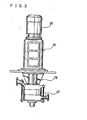
- the above-mentioned compression means 19 comprises a liquid oxygen pressurizing pump of the construction illustrated in Fig. 3.
- This pump comprises a motor mount 25, a high-speed motor 26 mounted on said motor mount, and a compression unit 27 with the interposition of an liquid oxygen leak seal 28. More specifically, as shown in Fig. 4, the pump includes a main shaft 35 which extends through the center of said motor mount 25, liquid oxygen leak seal 28 and compression unit 27 and is connected to a rotary shaft 26a of said motor 26 via a coupling 36.
- This main shaft 35 is rotatably supported by a bearing means 37 secured in position by a bearing cover 37a disposed within the motor mount 25 and a bearing 38 disposed at the end of the compression unit 27.
- the reference numeral 70 represents a sleeve.
- the compression unit 27 comprises a couple of spiral impellers 46 mounted on said main shaft 35 in upper and lower positions and a casing for accommodating the impellers 46.
- liquid oxygen is taken into a central suction port 46a of the impeller 46 and discharged in pressurized state from a peripheral discharge port 46b.-
- the impellers 46 are driven, the liquid oxygen is taken into a suction nozzle 48, pressurized by the first- stage impeller 46 and, after passage through a passageway 47, further.pressurized by the second-stage impeller 46, whereby the liquid oxygen is compressed to a predetermined pressure.
- the liquid oxygen leak seal 28 comprises a sleeve 50 surrounding said main shaft 35, a labyrinth 51 disposed around said sleeve 50 and a labyrinth cover 52 disposed further on said labyrinth 51, and serves to prevent leakage of liquid oxygen from the compression unit 27 and entry thereof into the motor mount 25 to cause an explosion.
- said motor mount 25 is divided into three gas-tight compartments so that liquid oxygen which may leak out will not reach the motor.
- the reference numeral 53 is an oxygen exhaust pipe which discharges liquid oxygen in gaseous state so that even if liquid oxygen leaks out from said seal 28, it will not reach the motor as it is.
- the above-mentioned oxygen pressurizing pump pressurizes the liquid oxygen which has been freed of impurities in the adsorption column 20 and sends it to the third heat exchanger 22, where it is heated by heat exchange with the nitrogen gas drawn out from the bottom column segment 12 via the pipe 12b.
- This oxygen is then fed to the first heat exchanger 8 and withdrawn into the product oxygen gas withdrawal pipe 21b as an atmospheric-temperature oxygen gas in pressurized state. In this manner, product oxygen gas in pressurized state is obtained.
- oxygen in gaseous state is pressurized in the first embodiment
- it is pressurized in liquid state in this embodiment to give a high purity oxygen gas in pressurized state so that the efficiency of pressurization is higher in this embodiment.
- the required pressurization can be accomplished with a reduced power, the product gas cost is reduced, and the equipment can be more compact.
- the volume of the gas is as large as 22.4 t per mole, a large-scale equipment is required for compression.
- the liquid is smaller in volume and, therefore, can be pressurized with comparative ease.
- oxygen is so reactive that in gaseous state it reacts with the lubricating oil for the pressurizing pump, for instance, to instantly cause an explosion. In liquid state, however, there is no such accident.
- the seal for the pump is easier and simpler for liquid oxygen than for gaseous oxygen.
- material air is first compressed and freed of impurities and, then, directly fed to the fractionation column 11.
- material air is preliminarily passed through a nitrogen eliminator 71 to provide an oxygen-rich air,which is then fed to the fractionation column 11.
- This nitrogen eliminator 71 is described in detail below with reference to Figs. 5 and 6.
- the reference numerals 62, 63 and 64 each represents a nitrogen adsorption column packed with an adsorbent (synthetic zeolite, molecular sieve) which selectively adsorbs N 2 .
- the inlets of these adsorbent columns are respectively connected to an air compressor pipe la through lines 62a, 63a and 64a fitted with valves 62b, 63b and 64b, respectively.
- the reference numeral 66 represents a vacuum pump which is connected to the inlets of said adsorption columns 62, 63 and 64 through a suction line 65 equipped with valves 62c, 63c and 64c.
- Indicated at 62d, 63d and 64d are discharge lines connected to the exits of said adsorption columns 62, 63 and 64 and provided with valves 62e, 63e and 64e, respectively. These discharge lines 62d, 63d and 64d are connected to a compressed air supply pipe 9.
- One of said adsorption columns 62, 63 and 64 is used for adsorption at a time, with the other two columns being subjected to vacuum suction regeneration by the vacuum pump 66, and one of the columns so regenerated is then used for adsorption.
- the above cycle is repeated for continuous adsorption of nitrogen gas.
- the use of this nitrogen eliminator 71 results in reduced material air requirements and product oxygen gas costs.
Landscapes
- Engineering & Computer Science (AREA)
- Physics & Mathematics (AREA)
- Mechanical Engineering (AREA)
- Thermal Sciences (AREA)
- General Engineering & Computer Science (AREA)
- Health & Medical Sciences (AREA)
- Emergency Medicine (AREA)
- Separation By Low-Temperature Treatments (AREA)
- Oxygen, Ozone, And Oxides In General (AREA)
Abstract
Description
- The present invention relates to an oxygen gas production apparatus which provides high purity gaseous oxygen in pressurized state.
- It is customary to produce oxygen gas in an air fractionation plant which separates oxygen from nitrogen by taking advantage of their difference in boiling point. This conventional air fractionation plant is provided with an expansion turbine for generating the refrigeration necessary for the liquefaction and fractionation of air, which utilizes the "cold heat" due to adiabatic expansion.
- However, because of its extremely high speed (tens of thousand revolutions per minute), the expansion turbine cannot delicately follow variations in load (variations in the rate of withdrawal of product oxygen gas). Thus, it is technically difficult to vary the rotational speed of the expansion turbine quickly and accurately in response to changes in the amount of withdrawal of product oxygen gas so as to maintain the compressed material air at a constant temperature at all times. As a result, a variation is inevitable in the purity of product oxygen gas, for low purity oxygen is frequently output to depress the overall purity of product oxygen. 'Furthermore, because it is driven at a very high speed, the expansion turbine demands high mechanical precision and is costly to manufacture. In addition, its complicated structure calls for specially trained maintenance personnel. These problems emanate generally from the high-speed-revolving component of the expansion turbine and there has been a strong demand for elimination of an expansion turbine having such a high-speed revolving element from the oxygen production installation.
- While product gaseous oxygen is sent to points of consumption via the product oxygen gas withdrawal line of the air fractionation plant, this transport is smoothly carried out when the pressure of product oxygen gas is high. Moreover, pressurized product oxygen gas is more convenient for consumption.
- Accomplished in view of the above state of the art, the present invention is directed to:
- (1) an oxygen gas production apparatus comprising an air compression means for compressing air from an outside source, a purification means for removing carbon dioxide gas and water vapor from the air compressed by said air compression means, a heat exchange means for chilling the compressed air from said purification means to a cryogenic temperature, a fractionation column for liquefying and fractionating the compressed air chilled to a cryogenic temperature by said heat exchange means and holding nitrogen in gaseous state and oxygen in liquid slater a liquid oxygen storage means for receiving liquid oxygen from an outside source and storing the same, a line for continuously introducing into said fractionation column the liquid oxygen from said liquid oxygen storage means in lieu of the generated refrigeration from a cold heat generating expansion means, an oxygen gas withdrawal line for guiding the liquid oxygen within said fractionation column as a refrigerant to said heat exchange means and withdrawing the gasified oxygen produced by heat exchange as a product oxygen gas, and a pressurizing means for pressurizing the product oxygen gas withdrawn from said oxygen withdrawal line; and
- (2) an oxygen gas production apparatus comprising an air compression means for compressing air from an outside source, a purification means for removing carbon dioxide gas and water vapor from the air compressed by said air compression means, a heat exchange means for chilling the compressed air from said purification means to a cryogenic temperature, a fractionation column for liquefying and fractionating the compressed air chilled to a cryogenic temperature by said heat exchange means and holding nitrogen in gaseous state and oxygen in liquid state, a liquid oxygen storage means for receiving liquid oxygen from an outside source and storing the same, a line for continuously introducing into said fractionation column the liquid oxygen from said liquid oxygen storage means in lieu of the generated refrigeration from a cold heat generating expansion means, a liquid oxygen withdrawal line for withdrawing liquid oxygen from said fractionation column, a pressurizing means for pressurizing the liquid oxygen from said liquid oxygen withdrawal line, and an oxygen gas withdrawal line for guiding the liquid oxygen pressurized by said pressurizing means to said heat exchange means as a refrigerant and withdrawing the gasified oxygen produced by heat exchange as a product oxygen gas.
- The advantages of the oxygen gas production apparatus according to the present invention include the following. Firstly, because it does not include an expansion turbine but, instead, uses a liquid oxygen storage means, such as a liquid oxygen storage tank, which has no revolving part, the whole equipment is virtually free of operation troubles and failures. Moreover, whereas the expansion turbine is an expensive machine, the liquid oxygen storage tank is available at low cost and does not call for special maintenance personnel. The expansion turbine is further disadvantageous in that since it cannot be easily driven to follow variations in load faithfully, i.e. at a varying rotational speed commensurate with the varying rate of withdrawal of product oxygen gas, the compressed air cannot be chilled to a predetermined temperature at all times. In contrast, the apparatus according to the present invention includes a liquid oxygen storage means in lieu of an expansion turbine and uses liquid oxygen which can be supplied at delicately controlled rates as a refrigeration medium so that product oxygen gas of very high purity can be obtained on a constant basis. In addition, because this apparatus is provided with a pressurizing means, the high-purity product oxygen can be made available in pressurized condition which is convenient in use at points of consumption. Particularly, the above principle of pressurizing liquid oxygen results in a remarkable improvement in the efficiency of compression, leading to drastic reductions in oxygen gas production cost and equipment scale. Moreover, since a liquid can be more easily compressed than a gas, the required seal may be less positive, so that it is easier to prevent oxygen leaks. In other words, the leakage of oxygen can be completely inhibited. Therefore, the present invention is a remarkable step forward from the standpoint of prevention of explosion and other hazards as well.
-
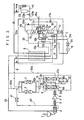
- Fig. 1 is an elementary view showing an embodiment of the present invention;
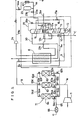
- Fig. 2 is an elementary view showing another embodiment of the invention;
- Fig. 3 is a plan view of a liquid oxygen compression pump;
- Fig. 4 is a cross-sectional view of the same; and
- Fig. 5 and 6 are elementary views illustrating modifications of the embodiments shown in Figs. 1 and 2.
- The present invention will be described below, taking preferred embodiments as examples. Referring to Fig. 1, which shows an embodiment of the present invention, the apparatus generally comprises a first air compressor 1, a waste heat recovery unit 2, an intercooler 3, a second air compressor 4, an after-
cooler 5, and a couple of air cooling columns 6, one of which (6a) is closed with the other (6b) communicating with anexhaust pipe 61. The apparatus further comprises a couple of adsorption columns 7, which are packed with molecular sieves and alternately operated to adsorb H20 and C02 in the air compressed by said first and second air compressors 1 and 4. Thereference numeral 8 represents a first heat exchanger which is supplied with the compressed air freed of H20 and C02 by said adsorption column 7 via a compressedair supply pipe 9 and by which said compressed air is chilled to a cryogenic temperature. - The
reference numeral 10 represents a second heat exchanger which is supplied with the compressed air freed of H20 and C02,through abranch pipe 9a branching out from said compressedair supply pipe 9. The compressed air fed into thissecond heat exchanger 10 is also chilled to a cryogenic temperature by heat exchange and, then, converges with the cryogenic compressed air from saidfirst heat exchanger 8. The oxygen production apparatus according to this embodiment further includes afractionation column 11, a bottom column of which is indicated at 12. In this fractionation column, the compressed air chilled to a cryogenic temperature by said first andsecond heat exchangers pipe 9 is further chilled and a portion thereof is liquefied and pooled in the bottom as liquefiedair 13, while nitrogen (containing small amounts of He, etc.) alone being held in gaseous state in the top. Thereference numeral 15 represents a top column segment of saidfractionation column 11 and has a built-in condenser 16. Thiscondenser 16 is supplied with a portion of nitrogen gas (containing small amounts of He gas, etc.) pooled in the top of thebottom column segment 12 of saidfractionation column 11 via apipe 12b and the nitrogen gas having a boiling point higher than that of He gas is liquefied and sent to aliquid nitrogen basin 12a in thebottom column segment 12 via apipe 12c, while the lower-boiling He gas is released as it is into the atmosphere via apipe 16a. The inside of saidtop column segment 15 is maintained in relatively decompressed condition as compared with the inside of saidbottom column segment 12, and the liquefied air (50-70% N2, 30-50% 02) 13 pooled in the bottom of saidbottom column 12 is introduced into the intermediate segment via apipe 18 fitted with anexpansion valve 17a, whereby its low- boiling fraction nitrogen is gasified and theliquid oxygen 21c collects in the bottom of thecolumn segment 15. In this connection, a portion of liquid nitrogen pooled in theliquid nitrogen basin 12a within thebottom column component 12 is sent to thetop column component 15 via apipe 29 fitted with anexpansion valve 29a for use as a reflux fluid in thetop column segment 15. Thereference numeral 30 represents a waste nitrogen gas withdrawal pipe for withdrawing the nitrogen fraction (not so high in purity) collected in the top of thetop column segment 15 as waste nitrogen gas. This waste nitrogen gas is guided to thefirst heat exchanger 8 where the material air is chilled by the refrigeration to a cryogenic temperature. The nitrogen gas is then guided to thecooling column 6b in the cooling column set 6 via abranch pipe 30a, where it is cooled by showers of water ejected from the tip nozzle of apipe 34. The waste nitrogen gas which has thus undergone heat exchange is released from apipe 61 into the atmosphere as indicated by arrowmark D. In this connection, a portion of the waste nitrogen gas taken out from thetop column segment 15 via thepipe 30. is utilized for regeneration of the one of said adsorption columns 7 which is not acting. Thus, the cryogenic waste nitrogen gas is guided from the.pipe 30 to the waste heat recovery unit 2 via apipe 39 and the resultant nitrogen gas at elevated temperature is fed to aregeneration heater 41 via apipe 40 to further increase its temperature. The heated nitrogen gas is fed to the idle adsorption column for regeneration of its molecular sieve and, then, released into the atmosphere viapipes pipe 30b is introduced to cool the molecular sieve and the waste nitrogen gas is released into the atmosphere as indicated by arrowmark D. The regeneration cycle is thus completed. The two adsorption columns 7 are alternately regenerated in the above manner. Thewater 31b cooled by waste nitrogen gas in thecooling column 6b collects in the bottom of thecolumn 6b and is sent by apump 32 via apipe 33 into the top of the closedcooling column 6a, where it flows down in the manner of a shower to cool the material air fed from said first and second air compressors 1, 4. Thewater 31a which has completed this cooling operation is returned to thecooling column 6b by the pressure gradient and cooled again by the refrigeration provided by waste nitrogen gas. To the bottom of saidtop column segment 15 is introduced a liquid oxygen via apipe 23a from a liquidoxygen storage tank 23 which is supplied with liquid oxygen from an external source and stores it, and this liquid oxygen is used to cool thecondenser 16 built into thetop column segment 15. Indicated at 21a is a gaseous oxygen withdrawal pipe for withdrawing the gasified fraction ofliquid oxygen 21c pooled in the bottom of thetop column segment 15. This pipe receives the gaseous oxygen taken at a level slightly above the level ofliquid oxygen 21c (purity 99.5%) and transports it to thefirst heat exchanger 8 where the oxygen gas is adjusted to atmospheric temperature by heat exchange with compressed air feed and sent to the productoxygen withdrawal pipe 21b. Indicated at 29c is a disposal pipe for disposing of theliquid oxygen 21c collected in the bottom of thetop column segment 15. This pipe sends theliquid oxygen 21c to thesecond heat exchanger 10 where it undergoes heat exchange with material air to chill the latter to a cryogenic temperature, after which it is released as indicated by arrowmark C. Thereference numeral 24 represents a compression means comprising an oxygen gas compressor disposed in the product oxygengas withdrawal pipe 21b. This compression means pressurizes the product oxygen gas to a prescribed pressure so that the product oxygen gas may be obtained in pressurized state. - The
reference numeral 44 represents a backup system line which opens avalve 44a in the event of a failure of the air compression system line, whereby the liquid oxygen in the liquidoxygen storage tank 23 is vaporized in anevaporator 45 and sent into thepipe 21b so as to prevent interruption of oxygen gas feed. Indicated by a dot-broken line is a vacuum cold housing which prevents entry of heat from outside for a further improvement of purification efficiency. - The apparatus described above produces product oxygen gas in pressurized state in the following manner.
- The air is compressed by the air compressor 1 and the resulting heat is recovered by the waste heat recovery unit 2. The compressed air is cooled by the intercooler 3, compressed by the air compressor 4, further cooled by the after-
cooler 5 and sent to theclosed cooling column 6a where it is contacted in counter current with the water cooled by waste nitrogen gas. The cooled air is fed to the adsorption column 7 wherein H20 and C02 are adsorbed and removed. A portion of the compressed air freed of H20 and C02 is fed via thepipe '9 into thefirst heat exchanger 8 where it is chilled to a cryogenic temperature, while the remainder is fed via thebranch pipe 9a into thesecond heat exchanger 10 where it is chilled to a cryogenic temperature. The two cryogenic air streams are combined and fed into the bottom of thebottom column segment 12. This compressed air is distilled by counter-current contact with overflowing liquid nitrogen from theliquid nitrogen basin 12a to liquefy the oxygen fraction and pool it in the bottom of thebottom column segment 12. In this process, by the difference in boiling point between nitrogen and oxygen (oxygen boils at -183°C and nitrogen boils at -196°C), the higher-boiling oxygen fraction of the compressed air is liquefied, while the nitrogen fraction remains gaseous. Accordingly the oxygen-richliquefied air 13 collects in the bottom of thebottom column segment 12. The liquefiedair 13 collected in the bottom of thebottom column segment 12 is subjected to adiabatic expansion at theexpansion valve 17a and sprayed from thepipe 18 into thetop column segment 15, where it contacts with the liquid nitrogen supplied into the top of thecolumn segment 15 from theliquid nitrogen basin 12a and flows down to the bottom of thecolumn segment 15. Here, by the same boiling point differential between nitrogen and oxygen as mentioned above, the higher-boiling fraction oxygen is liquefied and collects in the bottom while the nitrogen remains gaseous. Meanwhile, thetop column segment 15 is supplied with liquid oxygen as a refrigerant from the liquidoxygen storage tank 23 and this liquid oxygen intermingles with the above liquefied and separated liquid oxygen and the mixture collects in the bottom, andcools thecondenser 16 disposed within thetop column segment 15. On the other hand, the nitrogen gas separated in thecolumn segment 15 is for the most part drawn out-from the waste nitrogengas withdrawal pipe 30 for use as a refrigerant for thefirst heat exchanger 8, for preparation of cooling water for the air cooling column 6 and for regeneration of the adsorption column 7. The gas evaporated from the liquid oxygen collected in the bottom of thecolumn segment 15 in the above manner is withdrawn from the gaseousoxygen withdrawal pipe 21a, subjected to heat exchange in thefirst heat exchanger 8, pressurized to a predetermined pressure by the compression means 24 and sent out of the apparatus as an atmospheric-temperature product gas through thepipe 21b. In this manner, high-purity oxygen gas is obtained in pressurized state. - Referring, now, to Fig. 2 which shows another embodiment of the present invention, the oxygen gas production apparatus includes a compression means 19 for pressurizing liquid oxygen in a liquid
oxygen withdrawal pipe 21d in lieu of the compression means 24 for pressurizing the product oxygen gas, anadsorption column 20 for removal of the impurities such as methane and acetylene which collect in the bottom of acolumn segment 15, and athird heat exchanger 22. Since the construction of this embodiment is otherwise identical to that of the first embodiment, the same or corresponding parts are indicated by the like numerals. The above-mentioned compression means 19 comprises a liquid oxygen pressurizing pump of the construction illustrated in Fig. 3. This pump comprises amotor mount 25, a high-speed motor 26 mounted on said motor mount, and acompression unit 27 with the interposition of an liquidoxygen leak seal 28. More specifically, as shown in Fig. 4, the pump includes amain shaft 35 which extends through the center of saidmotor mount 25, liquidoxygen leak seal 28 andcompression unit 27 and is connected to arotary shaft 26a of saidmotor 26 via acoupling 36. Thismain shaft 35 is rotatably supported by a bearing means 37 secured in position by abearing cover 37a disposed within themotor mount 25 and abearing 38 disposed at the end of thecompression unit 27. Thereference numeral 70 represents a sleeve. Thecompression unit 27 comprises a couple ofspiral impellers 46 mounted on saidmain shaft 35 in upper and lower positions and a casing for accommodating theimpellers 46. By the rotation of themain shaft 35, liquid oxygen is taken into acentral suction port 46a of theimpeller 46 and discharged in pressurized state from a peripheral discharge port 46b.- Thus, as theimpellers 46 are driven, the liquid oxygen is taken into asuction nozzle 48, pressurized by the first-stage impeller 46 and, after passage through apassageway 47, further.pressurized by the second-stage impeller 46, whereby the liquid oxygen is compressed to a predetermined pressure. - The liquid
oxygen leak seal 28 comprises asleeve 50 surrounding saidmain shaft 35, alabyrinth 51 disposed around saidsleeve 50 and alabyrinth cover 52 disposed further on saidlabyrinth 51, and serves to prevent leakage of liquid oxygen from thecompression unit 27 and entry thereof into themotor mount 25 to cause an explosion. In this connection, saidmotor mount 25 is divided into three gas-tight compartments so that liquid oxygen which may leak out will not reach the motor. Thereference numeral 53 is an oxygen exhaust pipe which discharges liquid oxygen in gaseous state so that even if liquid oxygen leaks out from saidseal 28, it will not reach the motor as it is. - The above-mentioned oxygen pressurizing pump pressurizes the liquid oxygen which has been freed of impurities in the
adsorption column 20 and sends it to thethird heat exchanger 22, where it is heated by heat exchange with the nitrogen gas drawn out from thebottom column segment 12 via thepipe 12b. This oxygen is then fed to thefirst heat exchanger 8 and withdrawn into the product oxygengas withdrawal pipe 21b as an atmospheric-temperature oxygen gas in pressurized state. In this manner, product oxygen gas in pressurized state is obtained. - Thus, whereas oxygen in gaseous state is pressurized in the first embodiment, it is pressurized in liquid state in this embodiment to give a high purity oxygen gas in pressurized state so that the efficiency of pressurization is higher in this embodiment. Thus, the required pressurization can be accomplished with a reduced power, the product gas cost is reduced, and the equipment can be more compact. Thus, since the volume of the gas is as large as 22.4 t per mole, a large-scale equipment is required for compression. In contrast, the liquid is smaller in volume and, therefore, can be pressurized with comparative ease. Particularly, oxygen is so reactive that in gaseous state it reacts with the lubricating oil for the pressurizing pump, for instance, to instantly cause an explosion. In liquid state, however, there is no such accident. Moreover, the seal for the pump is easier and simpler for liquid oxygen than for gaseous oxygen.
- In the apparatus shown in Fig. 1 as an embodiment of the present invention and the apparatus shown in Fig. 2 as another embodiment, material air is first compressed and freed of impurities and, then, directly fed to the
fractionation column 11. In lieu of the above arrangement, it may be so arranged that, as shown in Figs. 5 and 6, material air 'is preliminarily passed through a nitrogen eliminator 71 to provide an oxygen-rich air,which is then fed to thefractionation column 11. This nitrogen eliminator 71 is described in detail below with reference to Figs. 5 and 6. The reference numerals 62, 63 and 64 each represents a nitrogen adsorption column packed with an adsorbent (synthetic zeolite, molecular sieve) which selectively adsorbs N2. The inlets of these adsorbent columns are respectively connected to an air compressor pipe la throughlines valves reference numeral 66 represents a vacuum pump which is connected to the inlets of saidadsorption columns suction line 65 equipped withvalves adsorption columns valves discharge lines air supply pipe 9. One of saidadsorption columns vacuum pump 66, and one of the columns so regenerated is then used for adsorption. The above cycle is repeated for continuous adsorption of nitrogen gas. The use of this nitrogen eliminator 71 results in reduced material air requirements and product oxygen gas costs.
Claims (2)
Applications Claiming Priority (2)
| Application Number | Priority Date | Filing Date | Title |
|---|---|---|---|
| JP60178232A JPH0721378B2 (en) | 1985-08-12 | 1985-08-12 | Oxygen gas production equipment |
| JP178232/85 | 1985-08-12 |
Publications (3)
| Publication Number | Publication Date |
|---|---|
| EP0232426A1 true EP0232426A1 (en) | 1987-08-19 |
| EP0232426A4 EP0232426A4 (en) | 1987-12-01 |
| EP0232426B1 EP0232426B1 (en) | 1991-03-13 |
Family
ID=16044902
Family Applications (1)
| Application Number | Title | Priority Date | Filing Date |
|---|---|---|---|
| EP86904928A Expired - Lifetime EP0232426B1 (en) | 1985-08-12 | 1986-08-08 | Oxygen gas production unit |
Country Status (4)
| Country | Link |
|---|---|
| US (1) | US4731102A (en) |
| EP (1) | EP0232426B1 (en) |
| JP (1) | JPH0721378B2 (en) |
| WO (1) | WO1987001184A1 (en) |
Cited By (2)
| Publication number | Priority date | Publication date | Assignee | Title |
|---|---|---|---|---|
| EP1612496A4 (en) * | 2003-03-26 | 2012-08-29 | Air Water Inc | Air separator |
| EP2873938A1 (en) * | 2013-11-14 | 2015-05-20 | L'air Liquide, Societe Anonyme Pour L'etude Et L'exploitation Des Procedes Georges Claude | Process and apparatus for the separation of air by cryogenic distillation |
Families Citing this family (20)
| Publication number | Priority date | Publication date | Assignee | Title |
|---|---|---|---|---|
| DE3817244A1 (en) * | 1988-05-20 | 1989-11-23 | Linde Ag | METHOD FOR DEEP TEMPERATURE DISPOSAL OF AIR |
| JP2551461B2 (en) * | 1988-07-04 | 1996-11-06 | 日本酸素 株式会社 | Pretreatment method of raw material air in air separation device |
| US5232474A (en) * | 1990-04-20 | 1993-08-03 | The Boc Group, Inc. | Pre-purification of air for separation |
| FR2670278B1 (en) * | 1990-12-06 | 1993-01-22 | Air Liquide | METHOD AND INSTALLATION FOR AIR DISTILLATION IN A VARIABLE REGIME FOR THE PRODUCTION OF GASEOUS OXYGEN. |
| FR2699992B1 (en) * | 1992-12-30 | 1995-02-10 | Air Liquide | Process and installation for producing gaseous oxygen under pressure. |
| US5462110A (en) * | 1993-12-30 | 1995-10-31 | Sarver; Donald L. | Closed loop air-cycle heating and cooling system |
| US5560763A (en) * | 1995-05-24 | 1996-10-01 | The Boc Group, Inc. | Integrated air separation process |
| US5987918A (en) * | 1998-03-17 | 1999-11-23 | The Boc Group, Inc. | Method of separating nitrogen from air |
| US6189329B1 (en) * | 2000-04-04 | 2001-02-20 | Venturedyne Limited | Cascade refrigeration system |
| CN100443838C (en) * | 2005-04-20 | 2008-12-17 | 苏州市兴鲁空分设备科技发展有限公司 | A method and device for reflux expansion air separation |
| US7827794B1 (en) * | 2005-11-04 | 2010-11-09 | Clean Energy Systems, Inc. | Ultra low emissions fast starting power plant |
| US7464557B2 (en) | 2006-02-15 | 2008-12-16 | David Vandor | System and method for cold recovery |
| EP2217869A4 (en) * | 2007-12-07 | 2015-06-24 | Dresser Rand Co | Compressor system and method for gas liquefaction system |
| FR2962799B1 (en) * | 2010-07-13 | 2014-07-04 | Air Liquide | COOLING ASSEMBLY AND APPARATUS FOR AIR SEPARATION BY CRYOGENIC DISTILLATION COMPRISING SUCH A COOLING ASSEMBLY |
| JP5910349B2 (en) * | 2012-06-27 | 2016-04-27 | Jfeスチール株式会社 | Raw material air cooling method and apparatus for air liquefaction separation equipment |
| US10578339B2 (en) * | 2013-01-28 | 2020-03-03 | Hitachi Industrial Equipment Systems Co., Ltd. | Waste-heat recovery system in oil-cooled gas compressor |
| CN106996680A (en) * | 2017-02-24 | 2017-08-01 | 杭州颐氧健康科技有限公司 | The anti-formula of noting of health care gas liquid oxygen is produced and feeder and its preparation method |
| US10712088B1 (en) * | 2017-05-05 | 2020-07-14 | L'Air Liquide, Société Anonyme pour l'Etude et l'Exploitation des Procédés Georges Claude | Temperature balancing for thermal integration of an air separation unit (ASU) with a power generation system |
| JP2019091348A (en) * | 2017-11-16 | 2019-06-13 | 富士通株式会社 | Information processing device |
| CN115265092A (en) * | 2022-07-27 | 2022-11-01 | 安徽马钢气体科技有限公司 | Low-temperature liquid adsorber cooling process and device |
Family Cites Families (11)
| Publication number | Priority date | Publication date | Assignee | Title |
|---|---|---|---|---|
| DE1067046B (en) * | 1956-01-04 | 1959-10-15 | Union Carbide Corporation, New York, N. Y. (V. St. A.) | Method for separating a gas mixture at low temperature and device for carrying out the method |
| US3039274A (en) * | 1958-03-28 | 1962-06-19 | Union Carbide Corp | Process and apparatus for purifying and separating compressed gas mixtures |
| DE1501723A1 (en) * | 1966-01-13 | 1969-06-26 | Linde Ag | Method and device for generating gaseous high-pressure oxygen in the low-temperature rectification of air |
| FR1479561A (en) * | 1966-03-25 | 1967-05-05 | Air Liquide | Variable flow rate gas pre-production process |
| JPS4940071B1 (en) * | 1970-01-09 | 1974-10-30 | ||
| JPS51105052U (en) * | 1975-02-21 | 1976-08-23 | ||
| GB2125949B (en) * | 1982-08-24 | 1985-09-11 | Air Prod & Chem | Plant for producing gaseous oxygen |
| GB2129115B (en) * | 1982-10-27 | 1986-03-12 | Air Prod & Chem | Producing gaseous nitrogen |
| US4617040A (en) * | 1983-03-08 | 1986-10-14 | Daidousanso Co., Ltd. | Highly pure nitrogen gas producing apparatus |
| JPS59231381A (en) * | 1983-06-15 | 1984-12-26 | 株式会社日立製作所 | Argon collection method using air separation equipment |
| JPS6060485A (en) * | 1983-09-12 | 1985-04-08 | 株式会社神戸製鋼所 | Method of separating air |
-
1985
- 1985-08-12 JP JP60178232A patent/JPH0721378B2/en not_active Expired - Fee Related
-
1986
- 1986-08-08 US US07/053,293 patent/US4731102A/en not_active Expired - Lifetime
- 1986-08-08 WO PCT/JP1986/000409 patent/WO1987001184A1/en not_active Ceased
- 1986-08-08 EP EP86904928A patent/EP0232426B1/en not_active Expired - Lifetime
Cited By (2)
| Publication number | Priority date | Publication date | Assignee | Title |
|---|---|---|---|---|
| EP1612496A4 (en) * | 2003-03-26 | 2012-08-29 | Air Water Inc | Air separator |
| EP2873938A1 (en) * | 2013-11-14 | 2015-05-20 | L'air Liquide, Societe Anonyme Pour L'etude Et L'exploitation Des Procedes Georges Claude | Process and apparatus for the separation of air by cryogenic distillation |
Also Published As
| Publication number | Publication date |
|---|---|
| WO1987001184A1 (en) | 1987-02-26 |
| EP0232426B1 (en) | 1991-03-13 |
| JPH0721378B2 (en) | 1995-03-08 |
| EP0232426A4 (en) | 1987-12-01 |
| US4731102A (en) | 1988-03-15 |
| JPS6237674A (en) | 1987-02-18 |
Similar Documents
| Publication | Publication Date | Title |
|---|---|---|
| US4731102A (en) | Oxygen gas production apparatus | |
| EP0235295B1 (en) | Oxygen gas production unit | |
| EP0211957B1 (en) | Apparatus for producing high-purity nitrogen and oxygen gases | |
| US4698079A (en) | High-purity nitrogen gas production equipment | |
| WO1984003554A1 (en) | Apparatus for producing high-purity nitrogen gas | |
| EP0190355B1 (en) | Apparatus for producing high-purity nitrogen gas | |
| US20090241595A1 (en) | Distillation method and apparatus | |
| US3057167A (en) | Process and apparatus for separating helium from helium-air mixtures | |
| KR890001743B1 (en) | Highly pure nitrogen gas producing apparatus | |
| EP0029656A1 (en) | Method and cryogenic plant for producing gaseous oxygen | |
| JPH06281322A (en) | High-purity nitrogen and oxygen gas production equipment | |
| JP2859663B2 (en) | Nitrogen gas and oxygen gas production equipment | |
| JP2686050B2 (en) | High-purity nitrogen gas production equipment | |
| KR900005986B1 (en) | High Purity Nitrogen Gas Production Equipment | |
| JP2859664B2 (en) | Nitrogen gas and oxygen gas production equipment | |
| JPH01239375A (en) | Device for manufacturing highly pure nitrogen gas | |
| JPH0626756A (en) | Oxygen gas production method | |
| JPS6148071B2 (en) | ||
| JPS6115070A (en) | Production unit for high-purity nitrogen gas | |
| JPS6152389B2 (en) | ||
| JPS6152390B2 (en) | ||
| JPS6217149B2 (en) | ||
| JPH06137756A (en) | Nitrogen production equipment | |
| JPH0318108B2 (en) | ||
| JPH04158186A (en) | Device for manufacturing ultra high purity nitrogen |
Legal Events
| Date | Code | Title | Description |
|---|---|---|---|
| PUAI | Public reference made under article 153(3) epc to a published international application that has entered the european phase |
Free format text: ORIGINAL CODE: 0009012 |
|
| AK | Designated contracting states |
Kind code of ref document: A1 Designated state(s): DE FR GB NL |
|
| 17P | Request for examination filed |
Effective date: 19870727 |
|
| A4 | Supplementary search report drawn up and despatched |
Effective date: 19871201 |
|
| 17Q | First examination report despatched |
Effective date: 19880923 |
|
| GRAA | (expected) grant |
Free format text: ORIGINAL CODE: 0009210 |
|
| AK | Designated contracting states |
Kind code of ref document: B1 Designated state(s): DE FR GB NL |
|
| REF | Corresponds to: |
Ref document number: 3678149 Country of ref document: DE Date of ref document: 19910418 |
|
| ET | Fr: translation filed | ||
| PLBI | Opposition filed |
Free format text: ORIGINAL CODE: 0009260 |
|
| 26 | Opposition filed |
Opponent name: LINDE AKTIENGESELLSCHAFT, WIESBADEN Effective date: 19911213 |
|
| NLR1 | Nl: opposition has been filed with the epo |
Opponent name: LINDE AG. |
|
| PLBN | Opposition rejected |
Free format text: ORIGINAL CODE: 0009273 |
|
| STAA | Information on the status of an ep patent application or granted ep patent |
Free format text: STATUS: OPPOSITION REJECTED |
|
| 27O | Opposition rejected |
Effective date: 19930701 |
|
| NLR2 | Nl: decision of opposition | ||
| NLS | Nl: assignments of ep-patents |
Owner name: DAIDO HOXAN INC. |
|
| REG | Reference to a national code |
Ref country code: FR Ref legal event code: TP |
|
| REG | Reference to a national code |
Ref country code: GB Ref legal event code: 732E |
|
| NLT1 | Nl: modifications of names registered in virtue of documents presented to the patent office pursuant to art. 16 a, paragraph 1 |
Owner name: AIR WATER INC. |
|
| REG | Reference to a national code |
Ref country code: FR Ref legal event code: CD |
|
| REG | Reference to a national code |
Ref country code: GB Ref legal event code: IF02 |
|
| PGFP | Annual fee paid to national office [announced via postgrant information from national office to epo] |
Ref country code: GB Payment date: 20050803 Year of fee payment: 20 |
|
| PGFP | Annual fee paid to national office [announced via postgrant information from national office to epo] |
Ref country code: DE Payment date: 20050804 Year of fee payment: 20 |
|
| PGFP | Annual fee paid to national office [announced via postgrant information from national office to epo] |
Ref country code: FR Payment date: 20050809 Year of fee payment: 20 |
|
| PGFP | Annual fee paid to national office [announced via postgrant information from national office to epo] |
Ref country code: NL Payment date: 20050815 Year of fee payment: 20 |
|
| REG | Reference to a national code |
Ref country code: GB Ref legal event code: PE20 |
|
| PG25 | Lapsed in a contracting state [announced via postgrant information from national office to epo] |
Ref country code: GB Free format text: LAPSE BECAUSE OF EXPIRATION OF PROTECTION Effective date: 20060807 |
|
| PG25 | Lapsed in a contracting state [announced via postgrant information from national office to epo] |
Ref country code: NL Free format text: LAPSE BECAUSE OF EXPIRATION OF PROTECTION Effective date: 20060808 |
|
| NLV7 | Nl: ceased due to reaching the maximum lifetime of a patent |
Effective date: 20060808 |