EP0232020B1 - Automatic sampling machine and method of use - Google Patents
Automatic sampling machine and method of use Download PDFInfo
- Publication number
- EP0232020B1 EP0232020B1 EP87300264A EP87300264A EP0232020B1 EP 0232020 B1 EP0232020 B1 EP 0232020B1 EP 87300264 A EP87300264 A EP 87300264A EP 87300264 A EP87300264 A EP 87300264A EP 0232020 B1 EP0232020 B1 EP 0232020B1
- Authority
- EP
- European Patent Office
- Prior art keywords
- motor
- timer
- gas
- pneumatic
- pump
- Prior art date
- Legal status (The legal status is an assumption and is not a legal conclusion. Google has not performed a legal analysis and makes no representation as to the accuracy of the status listed.)
- Expired - Lifetime
Links
- 238000005070 sampling Methods 0.000 title claims abstract description 28
- 238000000034 method Methods 0.000 title claims description 12
- 238000010926 purge Methods 0.000 claims abstract description 37
- 239000007788 liquid Substances 0.000 claims abstract description 25
- 230000002441 reversible effect Effects 0.000 claims abstract description 10
- 230000002572 peristaltic effect Effects 0.000 claims description 5
- 230000000977 initiatory effect Effects 0.000 claims description 2
- 239000007789 gas Substances 0.000 description 25
- 238000011109 contamination Methods 0.000 description 2
- 230000005611 electricity Effects 0.000 description 2
- 231100001261 hazardous Toxicity 0.000 description 2
- 238000007789 sealing Methods 0.000 description 2
- 239000007787 solid Substances 0.000 description 2
- 150000001298 alcohols Chemical class 0.000 description 1
- 238000005520 cutting process Methods 0.000 description 1
- 238000010586 diagram Methods 0.000 description 1
- 239000002360 explosive Substances 0.000 description 1
- 239000012530 fluid Substances 0.000 description 1
- 238000009434 installation Methods 0.000 description 1
- 238000009413 insulation Methods 0.000 description 1
- 238000002955 isolation Methods 0.000 description 1
- 238000012423 maintenance Methods 0.000 description 1
- 238000004519 manufacturing process Methods 0.000 description 1
- 230000001473 noxious effect Effects 0.000 description 1
- 239000003208 petroleum Substances 0.000 description 1
- 230000000717 retained effect Effects 0.000 description 1
- 238000003860 storage Methods 0.000 description 1
- 239000000126 substance Substances 0.000 description 1
- XLYOFNOQVPJJNP-UHFFFAOYSA-N water Substances O XLYOFNOQVPJJNP-UHFFFAOYSA-N 0.000 description 1
Images


Classifications
-
- G—PHYSICS
- G01—MEASURING; TESTING
- G01N—INVESTIGATING OR ANALYSING MATERIALS BY DETERMINING THEIR CHEMICAL OR PHYSICAL PROPERTIES
- G01N1/00—Sampling; Preparing specimens for investigation
- G01N1/02—Devices for withdrawing samples
- G01N1/10—Devices for withdrawing samples in the liquid or fluent state
- G01N1/14—Suction devices, e.g. pumps; Ejector devices
-
- G—PHYSICS
- G01—MEASURING; TESTING
- G01N—INVESTIGATING OR ANALYSING MATERIALS BY DETERMINING THEIR CHEMICAL OR PHYSICAL PROPERTIES
- G01N1/00—Sampling; Preparing specimens for investigation
- G01N1/02—Devices for withdrawing samples
- G01N1/10—Devices for withdrawing samples in the liquid or fluent state
- G01N1/14—Suction devices, e.g. pumps; Ejector devices
- G01N2001/1418—Depression, aspiration
- G01N2001/1427—Positive displacement, piston, peristaltic
-
- G—PHYSICS
- G01—MEASURING; TESTING
- G01N—INVESTIGATING OR ANALYSING MATERIALS BY DETERMINING THEIR CHEMICAL OR PHYSICAL PROPERTIES
- G01N1/00—Sampling; Preparing specimens for investigation
- G01N1/02—Devices for withdrawing samples
- G01N1/10—Devices for withdrawing samples in the liquid or fluent state
- G01N1/18—Devices for withdrawing samples in the liquid or fluent state with provision for splitting samples into portions
- G01N2001/185—Conveyor of containers successively filled
Definitions
- the present invention concerns the design and method of operation of a device for taking samples from sources of liquid such as bore holes, sumps, conduits carrying liquid chemicals such as petroleum or alcohols, a stream of water, sewers or effluent channels. It is particularly concerned with the provision of a machine to be used in environments which, by virtue of a susceptibility to flooding or the presence of noxious or flammable gases, are hostile.
- Sampling methods known at their simplest include manually taking a sample using a scoop or other such device.
- Clearly requiring the person sampling either to make repeated returns to the sample point or to remain at the sample point over an extended period of time is both an inefficient use of manpower and, in a hostile environment such as a sewer, potentially dangerous.
- a sampling machine capable of operating unattended is desirable.
- the sampling machine must therefore be capable of being portable. For the sampling machine to be taken to sites where access is difficult the machine must be compact and rugged.
- a device for automatically sampling liquids including a reversible gas powered motor having two inputs, associated gas lines connected fixedly to respective motor inputs for supplying a driving gas to the motor which in turn drives a reversible pump, control means being arranged to connect a source of driving gas via one of the gas lines to the motor so as to drive motor and pump in one sense for a predetermined period of time thus purging the pump thereafter to connect the source of the driving gas via the other of the gas lines to the motor having disconnected the source from said one of the gas lines to drive motor and pump in the opposite sense for a predetermined period of time thus drawing a sample of the liquid, and thereafter to disconnect the source of the driving gas from said other gas line thus stopping the motor
- the control means comprising a pneumatic purge timer and a first fluidic bistable device connected in series between the source of the driving gas and one of the gas lines supplying driving gas to the motor, a pneumatic sample timer and a second fluidic bistable device connected in series between the source of the
- FR-A-2343239 One past attempt at solving the problems a dressed by the present invention is disclose in FR-A-2343239.
- This machine is an electro-mechanical device having a reversible peristaltic pump driven by a conventional electric motor and, in the principal embodiment, a rotatable delivery tube driven by an electronically controlled stepper motor. In use the liquid drawn by the pump is transferred to the delivery tube and then to one of a number of fixed containers. Since, unlike the system of the present invention, this machine relies upon electricity for motive power and control it is inherently ill-adapted for use in hazardous areas. It is attempted to overcome this problem by sealing the electric motor within a plastic compartment.
- the sampling machine disclosed in FR-A-2343239 has further major disadvantages in that complete purging of the sampling/delivery system is not possible. Reversing the direction'of the peristaltic pump serves to purge the tubes directly connected to the pump but leaves the rotatable delivery tube unpurged. Any residues in the form of liquids or liquid-borne solids within the delivery tube will therefore tend to contaminate subsequent samples.
- the sampling sequence is initiated by starting the interval timer which determines the delay before purging and sampling operations.
- a signal to initiate a first mode of operation is sent to the purge timer and its associated bistable device, causing the gas supply to the first input of the motor to be tuned ON, so driving the motor and the pump in one sense to discharge any residue from a previous sample.
- a signal is sent to its associated bistable device, to the sample timer and to that timer's associated bistable device, turning OFF the driving gas supply to the first input of the motor, tuning ON the driving gas supply to the second input of the motor and starting the sample timer.
- This causes the motor and jump to operate in their opposite sense and draw a sample.
- Switching means connected to the supply lines for the first and second motor inputs and logically equivalent to a NOT gate then sense that both bistable devices are in the OFF position and send a signal to the interval timer resetting it to its original condition and initiating a repetition of the above operational sequence.
- control system is so arranged that in a first mode of operation the pump is driven in a sense such that a sample is drawn and then in a second mode of operation the pump is driven in the opposite sense purging any sample residue.
- the device may include a turntable or other movable device on which a number of containers for samples are mounted and means to cause the turntable or other movable device to advance to align a fresh container with the outlet of the pump.
- the control means may enable each container to remain stationary for a preset number of sampling/purging cycles so that the sample represents a time averaged state of the sampled liquid over an extended period or alternatively a fresh container may be used for each sampling/purging cycle.
- the timer may comprise a continuous extended period timer, however the interval timer preferably comprises a short period timer and an associated counter, the counter producing a pneumatic signal when the short period timer has gone through a pre-set number of cycles.
- the control system may include a delay timer to enable the apparatus to be pre-set to perform a sampling sequence or sequences at a time or times separated from the occasion of the initial setting of the device by a period of, for example, several hours or several weeks.
- a compressed air driven motor 1, a peristaltic pump 2 and a pneumatic control system 3 mounted on a connecting block 4 are all mounted on a base plate 5.
- Two supply lines 6 and 7 link the motor 1 to the control system 3.
- the pump 2 includes an inlet 8 and an outlet 9 for the sampled liquid.
- An air inlet 10 is connected to the pneumatic control system.
- the motor 1 is a conventional gas driven reversible rotary motor. In the preferred embodiment the motor 1 is of the low working volume type enabling the device to operate continuously for long periods. It is mechanically coupled to the adjacent peristaltic pump 2 which is the type commercially available as model no. 303 from Watson & Marlow Ltd. A line connected to the pump inlet 8 links the pump 2 to the source of the sampled liquid. A line connected to the pump outlet 9 carries the sampled liquid to a container (not shown) in which it is to be collected.
- the control system 3 is shown in detail in Figure 4 and includes three adjustable pneumatic timers, an interval timer 13, comprising a short period timer and an associated batch counter, purge timer 11 and a sample timer 12.
- the control system further includes two fluidic bistable devices, 14 and 15 one associated with the purge timer 11 and the other associated with the sample timer 12, a manually operable switch 16 and a fluidic NOT gate 17.
- the time period set on the sample timer 12 is smaller than that of the purge timer 11 which is in turn smaller than that of the interval timer 13.
- a pneumatic signal is produced and transmitted via airways in the connecting block 4 to the purge timer 11 and its associated fluidic bistable device 14.
- This fluidic bistable device 14 admits air from the air inlet 10 to a first input 18 of the motor 1, driving the motor 1 and hence the pump 2 in a first sense such that it draws air from the atmosphere and pumps it through the line connected to the sample inlet 8 so purging the residue of any previous liquid sample.
- the purge timer 11 At the expiry of the time period of the purge timer 11 it outputs a pneumatic signal which switches off its associated bistable device 14 switches on the sample timer 12 and switches on that timer's associated bistable device 15. Air is admitted through this bistable device 15 to a second input 19 of he motor 1 driving the motor 1 and hence the pump 2 in the opposite sense such that it draws a sample of liquid from the source through the line connected to the inlet 8 of the pump 2 and feeds it to the container (not shown) where it is retained.
- the time period set by sample timer 12 expires it outputs a pneumatic signal which switches off its associated bistable device 15 cutting off the air supply to the motor 1.
- the NOT gate 17 In response to the condition in which both bistable devices 14, 15 are OFF the NOT gate 17 produces a pneumatic signal which resets the interval timer 13 and initiates a new sampling cycle.
- the pump outlet 9 may deliver the sampled liquid to a container 20 mounted on the periphery of a turntable 21.
- the device includes a line 22 linking the control system 3 to a pneumatic motor 23 arranged to index the turntable bringing a fresh container 20 to the outlet 9 after each complete sampling cycle.
- the manually operable switch 16 is operated to transmit a signal to the purge timer and to its associated fluidic bistable device 14 to initiate a single cycle in which the pump 2 is purged and then a single sample is drawn.
Landscapes
- Life Sciences & Earth Sciences (AREA)
- Biochemistry (AREA)
- Physics & Mathematics (AREA)
- Health & Medical Sciences (AREA)
- Chemical & Material Sciences (AREA)
- Analytical Chemistry (AREA)
- Hydrology & Water Resources (AREA)
- General Health & Medical Sciences (AREA)
- General Physics & Mathematics (AREA)
- Immunology (AREA)
- Pathology (AREA)
- Sampling And Sample Adjustment (AREA)
- Measurement Of Radiation (AREA)
- Centrifugal Separators (AREA)
Abstract
Description
- The present invention concerns the design and method of operation of a device for taking samples from sources of liquid such as bore holes, sumps, conduits carrying liquid chemicals such as petroleum or alcohols, a stream of water, sewers or effluent channels. It is particularly concerned with the provision of a machine to be used in environments which, by virtue of a susceptibility to flooding or the presence of noxious or flammable gases, are hostile.
- Sampling methods known at their simplest include manually taking a sample using a scoop or other such device. Clearly requiring the person sampling either to make repeated returns to the sample point or to remain at the sample point over an extended period of time is both an inefficient use of manpower and, in a hostile environment such as a sewer, potentially dangerous. To overcome this disadvantage a sampling machine capable of operating unattended is desirable. In realising this objective a number of difficulties are to be overcome. When a multiplicity of sites are to be covered but samples are required only infrequently at any given site it is uneconomic to build fixed installations: the sampling machine must therefore be capable of being portable. For the sampling machine to be taken to sites where access is difficult the machine must be compact and rugged.
- The major difficulty is the requirement that the machine must be able to operate safely in the presence of liquids and/or potentially explosive gases. Electrically operated systems would have to be comprehensively insulated and isolated from their immediate environment to operate safely. Attaining this degree of insulation and isolation adds significantly to the cost of the device and makes it more difficult to obtain the goals of compactness and portability. In many situations the provision of a supply of electricity is difficult if not impossible. In addition to meeting these requirements the sampling machine must efficiently fulfill its prime purpose of drawing a series of samples over a period of time. To provide valid results it is desirable that each sample is discrete, i.e. that each sample is not contaminated with residues from any preceding sample.
- According to the present invention there is provided a device for automatically sampling liquids including a reversible gas powered motor having two inputs, associated gas lines connected fixedly to respective motor inputs for supplying a driving gas to the motor which in turn drives a reversible pump, control means being arranged to connect a source of driving gas via one of the gas lines to the motor so as to drive motor and pump in one sense for a predetermined period of time thus purging the pump thereafter to connect the source of the driving gas via the other of the gas lines to the motor having disconnected the source from said one of the gas lines to drive motor and pump in the opposite sense for a predetermined period of time thus drawing a sample of the liquid, and thereafter to disconnect the source of the driving gas from said other gas line thus stopping the motor, the control means comprising a pneumatic purge timer and a first fluidic bistable device connected in series between the source of the driving gas and one of the gas lines supplying driving gas to the motor, a pneumatic sample timer and a second fluidic bistable device connected in series between the source of the driving gas and the other of the lines supplying driving gas to the motor, the sample timer and the second fluidic bistable device being connected to receive a pneumatic signal from the purge timer, the device further comprising a pneumatic interval timer for controlling the interval between successive pairs of purging and sampling operations having one port connected to the source of driving gas and a second port connected to the pneumatic purge timer, and a fluidic NOT gate which is connected between the supply lines and to the pneumatic interval timer and arranged to transmit a pneumatic signal to the interval timer upon sensing that the supply of gas to the first and second inputs is OFF thereby resetting the pneumatic interval timer.
- One past attempt at solving the problems a dressed by the present invention is disclose in FR-A-2343239. This machine is an electro-mechanical device having a reversible peristaltic pump driven by a conventional electric motor and, in the principal embodiment, a rotatable delivery tube driven by an electronically controlled stepper motor. In use the liquid drawn by the pump is transferred to the delivery tube and then to one of a number of fixed containers. Since, unlike the system of the present invention, this machine relies upon electricity for motive power and control it is inherently ill-adapted for use in hazardous areas. It is attempted to overcome this problem by sealing the electric motor within a plastic compartment. Since it is necessary for the device's control panel to be accessible this cannot be positioned within the sealed compartment and so each of the switches on the control panel has to be individually sealed. Sealing all the electrical components to the high standards necessary for safe use in the presence of liquids and flammable gases necessarily adds significantly to the cost of manufacture and maintenance of the device and the need to have particular components positioned within sealed compartments contsrains the layout of the components within the device, limiting the extent to which its overall volume can be reduced.
- The sampling machine disclosed in FR-A-2343239 has further major disadvantages in that complete purging of the sampling/delivery system is not possible. Reversing the direction'of the peristaltic pump serves to purge the tubes directly connected to the pump but leaves the rotatable delivery tube unpurged. Any residues in the form of liquids or liquid-borne solids within the delivery tube will therefore tend to contaminate subsequent samples.
- delivery tube will therefore tend to contaminate subsequent samples.
- Another electrically powered sampling device is disclosed in US-A-3795347. This device uses a two-stage sampling process in which liquid is drawn under vacuum into a closed metering chamber until it rises to a predetermined level within the chamher and then the entire contents of the chamber are expelled under pressure into a storage vessel. Prior to a sample being drawn into the metering chamber pressure is applied to purge residues from the chamber and from a tube linking the source of liquid to the chamber. The device uses an electrially powered pump to pressurise the metering chamber and electrically powered timing and control devices. It therefore suffers all the attendent disadvantages discussed above in relation to FR 2343239. Moreover it is impossible for this device to be comprehensively insulated since it relies upon a pair of electrodes being exposed to the sample fluids in the metering chamber. It is therefore not possible to operate this device with complete safety in electrically hazardous environments. The two stage sampling process makes this device operationally less efficient than a device in accordance with the present invention in which the pump acts directly upon the liquids to draw a sample rather than being used indirectly to pressurise or evacuate an intermediate chamber. Since the process of purging can never be totally effective, particularly when liquid-borne solids are present, the use of an intermediate chamber provides an additional source of contamination of samples. Furthermore the tube leading from the metering chamber to the vessel for retaining the sample is not purged by the initial pressurisation of the chamber and so provides a further source of contamination. In all these respects this device contrasts with the present invention which provides a direct and easily purged connection between the source of the liquid and the outputs of the device.
- In a preferred method of operation of a device in accordance with the present invention the sampling sequence is initiated by starting the interval timer which determines the delay before purging and sampling operations. When the period set on the interval timer has elapsed a signal to initiate a first mode of operation is sent to the purge timer and its associated bistable device, causing the gas supply to the first input of the motor to be tuned ON, so driving the motor and the pump in one sense to discharge any residue from a previous sample. After the time set on the purging timer has elapsed a signal is sent to its associated bistable device, to the sample timer and to that timer's associated bistable device, turning OFF the driving gas supply to the first input of the motor, tuning ON the driving gas supply to the second input of the motor and starting the sample timer. This causes the motor and jump to operate in their opposite sense and draw a sample. When the period set on the sample timer elapses that timer sends a signal to its associated bistable device, tuning OFF the driving gas supply to the second input of the motor and hence removing power from the motor. Switching means connected to the supply lines for the first and second motor inputs and logically equivalent to a NOT gate then sense that both bistable devices are in the OFF position and send a signal to the interval timer resetting it to its original condition and initiating a repetition of the above operational sequence.
- In an alternative method of operation the control system is so arranged that in a first mode of operation the pump is driven in a sense such that a sample is drawn and then in a second mode of operation the pump is driven in the opposite sense purging any sample residue.
- The device may include a turntable or other movable device on which a number of containers for samples are mounted and means to cause the turntable or other movable device to advance to align a fresh container with the outlet of the pump. The control means may enable each container to remain stationary for a preset number of sampling/purging cycles so that the sample represents a time averaged state of the sampled liquid over an extended period or alternatively a fresh container may be used for each sampling/purging cycle.
- The timer may comprise a continuous extended period timer, however the interval timer preferably comprises a short period timer and an associated counter, the counter producing a pneumatic signal when the short period timer has gone through a pre-set number of cycles.
- The control system may include a delay timer to enable the apparatus to be pre-set to perform a sampling sequence or sequences at a time or times separated from the occasion of the initial setting of the device by a period of, for example, several hours or several weeks.
- A device in accordance with the present invention and its method of operation will now be described with reference to the accompanying drawings; in which:
- Figure 1 is a side elevation;
- Figure 2 is a front elevation;
- Figure 3 is a plan;
- Figure 4 is a pneumatic circuit diagram;
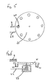
- Figure 5 is a plan of a turntable; and,
- Figure 6 is a partially sectioned side elevation of a turntable.
- A compressed air driven
motor 1, aperistaltic pump 2 and apneumatic control system 3 mounted on a connectingblock 4 are all mounted on abase plate 5. Twosupply lines 6 and 7 link themotor 1 to thecontrol system 3. Thepump 2 includes aninlet 8 and anoutlet 9 for the sampled liquid. Anair inlet 10 is connected to the pneumatic control system. - The
motor 1 is a conventional gas driven reversible rotary motor. In the preferred embodiment themotor 1 is of the low working volume type enabling the device to operate continuously for long periods. It is mechanically coupled to the adjacentperistaltic pump 2 which is the type commercially available as model no. 303 from Watson & Marlow Ltd. A line connected to thepump inlet 8 links thepump 2 to the source of the sampled liquid. A line connected to thepump outlet 9 carries the sampled liquid to a container (not shown) in which it is to be collected. - The
control system 3 is shown in detail in Figure 4 and includes three adjustable pneumatic timers, aninterval timer 13, comprising a short period timer and an associated batch counter,purge timer 11 and asample timer 12. The control system further includes two fluidic bistable devices, 14 and 15 one associated with thepurge timer 11 and the other associated with thesample timer 12, a manuallyoperable switch 16 and afluidic NOT gate 17. The time period set on thesample timer 12 is smaller than that of thepurge timer 11 which is in turn smaller than that of theinterval timer 13. - To initiate a sampling sequence compressed air is admitted to the
main air inlet 10 and this starts the timing period of theinterval timer 13. When the time pre-set on theinterval timer 13 has expired a pneumatic signal is produced and transmitted via airways in the connectingblock 4 to thepurge timer 11 and its associated fluidicbistable device 14. This fluidicbistable device 14 admits air from theair inlet 10 to a first input 18 of themotor 1, driving themotor 1 and hence thepump 2 in a first sense such that it draws air from the atmosphere and pumps it through the line connected to thesample inlet 8 so purging the residue of any previous liquid sample. - At the expiry of the time period of the
purge timer 11 it outputs a pneumatic signal which switches off its associatedbistable device 14 switches on thesample timer 12 and switches on that timer's associatedbistable device 15. Air is admitted through thisbistable device 15 to asecond input 19 of he motor 1 driving themotor 1 and hence thepump 2 in the opposite sense such that it draws a sample of liquid from the source through the line connected to theinlet 8 of thepump 2 and feeds it to the container (not shown) where it is retained. When the time period set bysample timer 12 expires it outputs a pneumatic signal which switches off its associatedbistable device 15 cutting off the air supply to themotor 1. In response to the condition in which bothbistable devices NOT gate 17 produces a pneumatic signal which resets theinterval timer 13 and initiates a new sampling cycle. - As shown in Figures 5 and 6, the
pump outlet 9 may deliver the sampled liquid to acontainer 20 mounted on the periphery of aturntable 21. In this embodiment the device includes aline 22 linking thecontrol system 3 to apneumatic motor 23 arranged to index the turntable bringing afresh container 20 to theoutlet 9 after each complete sampling cycle. - In an alternative method of operation the manually
operable switch 16 is operated to transmit a signal to the purge timer and to its associated fluidicbistable device 14 to initiate a single cycle in which thepump 2 is purged and then a single sample is drawn.
Claims (4)
the method comprising initiating the interval timer (13); when the period set on the interval timer (13) has elapsed sending a signal from the latter to the pneumatic purge timer (11) to initiate a first mode of operation of the purge timer (11) and its associated bistable device (14) causing the gas supply to the first input (18) of the motor (1) to be turned ON, so driving the motor (1) and the pump (2) in one sense to discharge any residue from a previous sample; after the time set on the purge timer (11) has elapsed sending signals from the latter to its associated fluidic bistable device (14), so as to turn OFF the driving gas supply via said one of the gas lines to the motor (1) and so as to turn ON the fluidic bistable device (15) associated with the pneumatic sample timer (12) turning ON the driving gas supply to the second input of the motor (19) causing the motor and pump to operate in their opposite sense and draw a sample, and to the pneumatic sample timer (12) so as to start the pneumatic sample timer (12); when the period set on the pneumatic sample timer (12) has elapsed sending a signal from the latter to its associated bistable device (15), turning OFF the driving gas supply to the second input (19) of the motor (1) and hence removing power from the motor (1); and sensing via the inputs to the fluidic NOT gate (17) when both bistable devices (14, 15) are in the OFF position and sending a signal from the fluidic NOT gate (17) to the interval timer (13) to initiate a repetition of the operational sequence.
Priority Applications (1)
| Application Number | Priority Date | Filing Date | Title |
|---|---|---|---|
| AT87300264T ATE62997T1 (en) | 1986-01-14 | 1987-01-13 | AUTOMATIC DEVICE AND PROCEDURE FOR TAKING SAMPLES. |
Applications Claiming Priority (2)
| Application Number | Priority Date | Filing Date | Title |
|---|---|---|---|
| GB868600780A GB8600780D0 (en) | 1986-01-14 | 1986-01-14 | Automatic sampling machine |
| GB8600780 | 1986-01-14 |
Publications (2)
| Publication Number | Publication Date |
|---|---|
| EP0232020A1 EP0232020A1 (en) | 1987-08-12 |
| EP0232020B1 true EP0232020B1 (en) | 1991-04-24 |
Family
ID=10591337
Family Applications (1)
| Application Number | Title | Priority Date | Filing Date |
|---|---|---|---|
| EP87300264A Expired - Lifetime EP0232020B1 (en) | 1986-01-14 | 1987-01-13 | Automatic sampling machine and method of use |
Country Status (5)
| Country | Link |
|---|---|
| US (1) | US4831887A (en) |
| EP (1) | EP0232020B1 (en) |
| AT (1) | ATE62997T1 (en) |
| DE (1) | DE3769485D1 (en) |
| GB (1) | GB8600780D0 (en) |
Families Citing this family (6)
| Publication number | Priority date | Publication date | Assignee | Title |
|---|---|---|---|---|
| US4986138A (en) * | 1985-04-05 | 1991-01-22 | Spencer R Wilson | Sample injection means |
| US5003830A (en) * | 1987-05-29 | 1991-04-02 | Spencer R Wilson | Sample extraction system |
| EP0574412B1 (en) * | 1991-03-05 | 1997-08-06 | R.J. FULLWOOD & BLAND LIMITED | Milk sampling for diagnostic purposes |
| WO1998030254A2 (en) * | 1997-01-10 | 1998-07-16 | Emory University | Sample collection and drug delivery apparatus for freely-moving tethered laboratory animals |
| CN108332995A (en) * | 2017-01-20 | 2018-07-27 | 上海溯源生物技术有限公司 | Sampler |
| US11598696B2 (en) * | 2019-06-14 | 2023-03-07 | Emerald Coast Manufacturing, LLC | Method and apparatus for sampling liquid |
Family Cites Families (10)
| Publication number | Priority date | Publication date | Assignee | Title |
|---|---|---|---|---|
| US3039309A (en) * | 1957-09-13 | 1962-06-19 | Phillips Petroleum Co | Pneumatically actuated pump and sampling system |
| US3782197A (en) * | 1971-05-10 | 1974-01-01 | R Grams | Biological fluid sampling and testing apparatus |
| US3795347A (en) * | 1972-02-03 | 1974-03-05 | E Singer | Power purged liquid sampler |
| US4023417A (en) * | 1973-06-13 | 1977-05-17 | Pro-Tech Inc. | Liquid sampling |
| US3924471A (en) * | 1974-02-07 | 1975-12-09 | Ernst Singer | Automatic liquid sample taking and segregating apparatus |
| FR2343239A1 (en) * | 1976-03-02 | 1977-09-30 | Secmapp Sa | Automatic sampling appts. and control unit - using a moveable delivery nozzle and fixed large sample bottles in an insulated, airtight container |
| US4037472A (en) * | 1976-09-16 | 1977-07-26 | Advanced Instrumentation Inc. | Explosion-proof flow sampling apparatus |
| US4418581A (en) * | 1980-05-13 | 1983-12-06 | Jones Richard W | Apparatus and method for sampling a liquid |
| US4489779A (en) * | 1983-02-28 | 1984-12-25 | Quantitative Environmental Decisions Corporation | Fluid sampling apparatus |
| US4604166A (en) * | 1984-08-28 | 1986-08-05 | Amdev, Inc. | Apparatus and process for reducing peristaltic pump noise in a high impedance electrochemical measuring system |
-
1986
- 1986-01-14 GB GB868600780A patent/GB8600780D0/en active Pending
-
1987
- 1987-01-13 EP EP87300264A patent/EP0232020B1/en not_active Expired - Lifetime
- 1987-01-13 DE DE8787300264T patent/DE3769485D1/en not_active Expired - Fee Related
- 1987-01-13 AT AT87300264T patent/ATE62997T1/en not_active IP Right Cessation
- 1987-01-14 US US07/003,278 patent/US4831887A/en not_active Expired - Fee Related
Also Published As
| Publication number | Publication date |
|---|---|
| US4831887A (en) | 1989-05-23 |
| GB8600780D0 (en) | 1986-02-19 |
| ATE62997T1 (en) | 1991-05-15 |
| DE3769485D1 (en) | 1991-05-29 |
| EP0232020A1 (en) | 1987-08-12 |
Similar Documents
| Publication | Publication Date | Title |
|---|---|---|
| US4831887A (en) | Automatic sampling machine | |
| US5443734A (en) | Programmable solid phase extraction and elution device | |
| US3651989A (en) | Liquid metering system | |
| US6036445A (en) | Electric shifting mechanism/interface for fluid power diaphragm pumps | |
| EP0809164A1 (en) | Control system for controlling a plurality of vacuum pumps | |
| GB1371678A (en) | Blood processing apparatus | |
| US4552162A (en) | Electric combination cleaner | |
| CA2211425A1 (en) | Hand-held electric mixer | |
| US3647971A (en) | Automatic reporting monitoring and control system | |
| US3563384A (en) | Automatic macerator unit | |
| DE50111572D1 (en) | Vacuum chamber with heating plate for filtering and removing liquids | |
| EP0575125B1 (en) | Method and apparatus for wet chemical processing of semiconductor wafers and other objects | |
| TW343940B (en) | Device for controlling hydraulic driving tool | |
| US6149869A (en) | Chemical synthesizers | |
| US3049267A (en) | Multiple-feed spray guns | |
| GB1402965A (en) | Machine for delivering and mixing at least two reaction components | |
| BR8703397A (en) | SYSTEM FOR THE ELECTRICAL SEQUENTIAL INITIALIZATION OF EXPLOSIONS AND INITIATOR MODULE SUITABLE FOR USE IN THE SAME | |
| CN211262859U (en) | A water quality sampling device | |
| US3155049A (en) | Duplex liquid handling apparatus having improved electrode-type control system | |
| US3525596A (en) | Controlled discharge means for reaction apparatus | |
| CN210698851U (en) | Reduced pressure distillation device | |
| WO1988007275A1 (en) | Abnormal condition detector in a laser oscillator conduit system | |
| US4181022A (en) | Pressure rise tube sampler | |
| US3550606A (en) | Fluidic sequentials switching system | |
| JP3305760B2 (en) | Control device for automatic water supply |
Legal Events
| Date | Code | Title | Description |
|---|---|---|---|
| PUAI | Public reference made under article 153(3) epc to a published international application that has entered the european phase |
Free format text: ORIGINAL CODE: 0009012 |
|
| AK | Designated contracting states |
Kind code of ref document: A1 Designated state(s): AT BE CH DE ES FR GB GR IT LI LU NL SE |
|
| 17P | Request for examination filed |
Effective date: 19880121 |
|
| 17Q | First examination report despatched |
Effective date: 19890424 |
|
| GRAA | (expected) grant |
Free format text: ORIGINAL CODE: 0009210 |
|
| AK | Designated contracting states |
Kind code of ref document: B1 Designated state(s): AT BE CH DE ES FR GB GR IT LI LU NL SE |
|
| PG25 | Lapsed in a contracting state [announced via postgrant information from national office to epo] |
Ref country code: IT Free format text: LAPSE BECAUSE OF FAILURE TO SUBMIT A TRANSLATION OF THE DESCRIPTION OR TO PAY THE FEE WITHIN THE PRESCRIBED TIME-LIMIT;WARNING: LAPSES OF ITALIAN PATENTS WITH EFFECTIVE DATE BEFORE 2007 MAY HAVE OCCURRED AT ANY TIME BEFORE 2007. THE CORRECT EFFECTIVE DATE MAY BE DIFFERENT FROM THE ONE RECORDED. Effective date: 19910424 Ref country code: LI Effective date: 19910424 Ref country code: NL Effective date: 19910424 Ref country code: SE Effective date: 19910424 Ref country code: BE Effective date: 19910424 Ref country code: AT Effective date: 19910424 Ref country code: FR Effective date: 19910424 Ref country code: GR Free format text: LAPSE BECAUSE OF FAILURE TO SUBMIT A TRANSLATION OF THE DESCRIPTION OR TO PAY THE FEE WITHIN THE PRESCRIBED TIME-LIMIT Effective date: 19910424 Ref country code: CH Effective date: 19910424 |
|
| REF | Corresponds to: |
Ref document number: 62997 Country of ref document: AT Date of ref document: 19910515 Kind code of ref document: T |
|
| REF | Corresponds to: |
Ref document number: 3769485 Country of ref document: DE Date of ref document: 19910529 |
|
| RAP2 | Party data changed (patent owner data changed or rights of a patent transferred) |
Owner name: THAMES WATER UTILITIES LIMITED |
|
| REG | Reference to a national code |
Ref country code: CH Ref legal event code: PL |
|
| PG25 | Lapsed in a contracting state [announced via postgrant information from national office to epo] |
Ref country code: ES Free format text: LAPSE BECAUSE OF FAILURE TO SUBMIT A TRANSLATION OF THE DESCRIPTION OR TO PAY THE FEE WITHIN THE PRESCRIBED TIME-LIMIT Effective date: 19910804 |
|
| NLV1 | Nl: lapsed or annulled due to failure to fulfill the requirements of art. 29p and 29m of the patents act | ||
| EN | Fr: translation not filed | ||
| BECN | Be: change of holder's name |
Effective date: 19910424 |
|
| PG25 | Lapsed in a contracting state [announced via postgrant information from national office to epo] |
Ref country code: LU Free format text: LAPSE BECAUSE OF NON-PAYMENT OF DUE FEES Effective date: 19920131 |
|
| PLBE | No opposition filed within time limit |
Free format text: ORIGINAL CODE: 0009261 |
|
| STAA | Information on the status of an ep patent application or granted ep patent |
Free format text: STATUS: NO OPPOSITION FILED WITHIN TIME LIMIT |
|
| 26N | No opposition filed | ||
| PGFP | Annual fee paid to national office [announced via postgrant information from national office to epo] |
Ref country code: GB Payment date: 19930104 Year of fee payment: 7 |
|
| PGFP | Annual fee paid to national office [announced via postgrant information from national office to epo] |
Ref country code: DE Payment date: 19930115 Year of fee payment: 7 |
|
| PG25 | Lapsed in a contracting state [announced via postgrant information from national office to epo] |
Ref country code: GB Effective date: 19940113 |
|
| GBPC | Gb: european patent ceased through non-payment of renewal fee |
Effective date: 19940113 |
|
| PG25 | Lapsed in a contracting state [announced via postgrant information from national office to epo] |
Ref country code: DE Effective date: 19941001 |