EP0232010B1 - Acoustic energy transmitter for borehole logging - Google Patents
Acoustic energy transmitter for borehole logging Download PDFInfo
- Publication number
- EP0232010B1 EP0232010B1 EP87300155A EP87300155A EP0232010B1 EP 0232010 B1 EP0232010 B1 EP 0232010B1 EP 87300155 A EP87300155 A EP 87300155A EP 87300155 A EP87300155 A EP 87300155A EP 0232010 B1 EP0232010 B1 EP 0232010B1
- Authority
- EP
- European Patent Office
- Prior art keywords
- acoustic
- source
- pipe
- flexure
- borehole
- Prior art date
- Legal status (The legal status is an assumption and is not a legal conclusion. Google has not performed a legal analysis and makes no representation as to the accuracy of the status listed.)
- Expired
Links
- 229920001971 elastomer Polymers 0.000 claims description 12
- 239000012530 fluid Substances 0.000 claims description 9
- 230000008878 coupling Effects 0.000 claims description 2
- 238000010168 coupling process Methods 0.000 claims description 2
- 238000005859 coupling reaction Methods 0.000 claims description 2
- 239000011810 insulating material Substances 0.000 claims 1
- 238000007789 sealing Methods 0.000 claims 1
- 230000015572 biosynthetic process Effects 0.000 description 10
- 238000005755 formation reaction Methods 0.000 description 10
- 239000000463 material Substances 0.000 description 4
- 238000000034 method Methods 0.000 description 3
- 229910000831 Steel Inorganic materials 0.000 description 2
- 238000013016 damping Methods 0.000 description 2
- 230000007717 exclusion Effects 0.000 description 2
- 230000003252 repetitive effect Effects 0.000 description 2
- 239000007787 solid Substances 0.000 description 2
- 239000010959 steel Substances 0.000 description 2
- 238000004458 analytical method Methods 0.000 description 1
- 238000005452 bending Methods 0.000 description 1
- 239000000919 ceramic Substances 0.000 description 1
- 239000004020 conductor Substances 0.000 description 1
- 230000008602 contraction Effects 0.000 description 1
- 230000001419 dependent effect Effects 0.000 description 1
- 230000005284 excitation Effects 0.000 description 1
- 238000004519 manufacturing process Methods 0.000 description 1
- 230000003534 oscillatory effect Effects 0.000 description 1
- 239000002245 particle Substances 0.000 description 1
- 229920001084 poly(chloroprene) Polymers 0.000 description 1
- 239000010409 thin film Substances 0.000 description 1
Images


Classifications
-
- G—PHYSICS
- G01—MEASURING; TESTING
- G01V—GEOPHYSICS; GRAVITATIONAL MEASUREMENTS; DETECTING MASSES OR OBJECTS; TAGS
- G01V1/00—Seismology; Seismic or acoustic prospecting or detecting
- G01V1/40—Seismology; Seismic or acoustic prospecting or detecting specially adapted for well-logging
- G01V1/52—Structural details
-
- B—PERFORMING OPERATIONS; TRANSPORTING
- B06—GENERATING OR TRANSMITTING MECHANICAL VIBRATIONS IN GENERAL
- B06B—METHODS OR APPARATUS FOR GENERATING OR TRANSMITTING MECHANICAL VIBRATIONS OF INFRASONIC, SONIC, OR ULTRASONIC FREQUENCY, e.g. FOR PERFORMING MECHANICAL WORK IN GENERAL
- B06B1/00—Methods or apparatus for generating mechanical vibrations of infrasonic, sonic, or ultrasonic frequency
- B06B1/02—Methods or apparatus for generating mechanical vibrations of infrasonic, sonic, or ultrasonic frequency making use of electrical energy
- B06B1/06—Methods or apparatus for generating mechanical vibrations of infrasonic, sonic, or ultrasonic frequency making use of electrical energy operating with piezoelectric effect or with electrostriction
- B06B1/0603—Methods or apparatus for generating mechanical vibrations of infrasonic, sonic, or ultrasonic frequency making use of electrical energy operating with piezoelectric effect or with electrostriction using a piezoelectric bender, e.g. bimorph
Definitions
- This invention relates to an acoustic energy transmitter for borehole logging.
- a low-frequency acoustic transmitter for borehole logging as defined in claim 1.
- the low frequency acoustic transmitter 30 of said one example comprises a hollow cylindrical housing 33 closed at both ends by cap members 34 and 35.
- a low-frequency acoustic transducer 32 mounted within the inner cavity 31 of the housing 33.
- a pair of rod-like members 36 and 37 extend through the inner cavity 31 between the cap members 34 and 35.
- a mounting band 40 is affixed to the rod-like members 36 and 37 at the midpoint of the inner cavity 31.
- a mounting band 40 is in the form of a ring member 41 which is recessed internally to receive a rubber member 42.
- an acoustic transducer 32 which comprises a pipe 45 and flexure disc source 46.
- the cylindrical housing 33 includes a plurality of slots 49 along its length so as to allow the rubber boot 47 to be exposed to the borehole fluid.
- the change in shape of the source 46 may be preferably from a flat shape in the absence of the applied potential to a dish shape in the presence of the applied potential.
- the repetitive bending or flexing of the source 46 acts on the oil within the pipe 45 in a diaphragm-like action to produce the desired acoustic energy wave.
- FIG. 4 One such flexing motion is illustrated in FIG. 4, in which the dashed lines indicate the flat shape of the source 46, and the solid line representing the flexed shape of source 46.
- a particularly suitable flexure disc source is that described in detail in U.S. Patent No. 3,363,118.
Description
- This invention relates to an acoustic energy transmitter for borehole logging.
- In acoustic borehole logging, an acoustic energy transmitter and one or more receivers disposed at spaced-apart distances from the transmitter are included in a borehole logging tool that is moved through a borehole. Acoustic energy waves generated by the transmitter travel through the subsurface formations surrounding the borehole and are detected by the receiver or receivers. One such borehole logging tool is described in U.S. Patent No. 4,383,308.
- Typically, acoustic energy waves provided by conventional borehole logging tools include both headwaves and guided waves. A first arriving event is a headwave, commonly called a compressional wave, which represents acoustic energy which has been refracted through the formation adjacent the wellbore. This compressional wave travels as a fluid pressure wave in the wellbore mud from the transmitter to the formation where it travels at the compressional wave velocity of the particular formation. The compressional wave then travels to the receiver through the wellbore mud as a fluid pressure wave.
- A second arriving event is a headwave, commonly called a shear wave, which is also refracted through the formation adjacent the wellbore. Unlike the compressional wave, the shear wave travels at shear velocity through the formations. The particles of the formation along the path of propagation are vibrated in a direction perpendicular to the direction of the propagation of the wave.
- A third arriving event is a guided wave, commonly called a tube wave or Stoneley wave, which causes a radial bulging and contraction of the borehole, and its travel is by way of the borehole wall; that is, the boundary between the borehold fluids and the formation solids.
- A fourth arriving event is a guided wave, commonly called a normal mode, pseudo-Rayleight wave, or reflected conical wave. The travel of this normal mode is restricted to the borehole and has an oscillatory pattern normal to its direction of travel. Normally, the shear wave is indistinguishable from the onset of this normal mode due to concurrent arrival times.
- Various signal timing and wave front analysis methods have been suggested for distinguishing between these various wave fronts received at a given receiver. Most of these methods involve timing circuits which anticipate the receipt of, and facilitate the collection of, such wave front information. For descriptions of various logging techniques for collecting and analyzing acoustic wave data, reference is directed to U.S. Patents Nos. 3,333,238; 3,362,011; Reissue No. 24,446; and 4,383,308.
- Heretofore, well logging tools have transmitted such acoustic energy waves at frequencies of several kilohertiz, while conventional seismic energy waves have obtained at much lower frequencies of a few hundred hertz or less. It is a specific feature of the present invention to provide an acoustic transmitter for use in a borehole logging tool that will produce acoustic energy waves in the typical seismic frequency range of a few hundred hertz or less, particularly tube waves.
- In US-A-3187300 there is disclosed a pressure compensated transducer which may be employed as a hydrophone or as an acoustic projector.
- The transducer comprises a cylindrical casing having a piezoelectric disc element positioned at each end of the casing. A hose section (which may be neoprene) surrounds the cylindrical casing and disc elements, and is provided with an end cap at each end thereof.
- The hose section is filled with oil, as is the casing, and the surrounding fluid pressure can be transmitted through the hose section to the oil.
- The disc elements sense acoustic pressure waves from the surrounding environment and create an electrical signal indictive thereof.
- According to the present invention there is provided a low-frequency acoustic transmitter for borehole logging, as defined in claim 1.
- Further features of the invention are defined in the dependent claims.
- In the accompanying drawings,
- FIG. 1 is a diagrammatic representation of a borehole acoustic velocity logging system employing an acoustic transmitter according to one example of the present invention;
- FIG. 2 illustrates a set of acoustic energy waveforms that are typically transmitted through subsurface formations surrounding a borehole by a logging tool using a conventional acoustic source.
- FIG. 3 is a detailed cross-sectional view of the acoustic transmitter of said one example of the invention;
- FIG. 4 illustrates the flexure motion of the acoustic energy source of the acoustic transmitter of FIG. 3 in producing low-frequency tube waves.
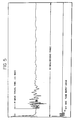
- FIGS. 5 and 6 illustrate compressional waves generated within the borehole at 0.4 and 1.2 kHz, respectively, by the acoustic transmitter of FIG. 3; and
- FIGS. 7 and 8 illustrate tube waves generated within the borehole at 2.4 and 4.0 kHz, respectively, by the acoustic transmitter of FIG. 3.
- Referring now to FIG. 1, there will firstly be described a conventional borehole acoustic velocity logging system with which the low-frequency acoustic transmitter of the present invention may be utilized. The system includes a
logging tool 10 which is suspended by acable 12 for movement along the length of a borehole 14. The logging tool includes an acoustic source ortransmitter 16 for the production of repetitive time-spaced pulses of acoustic energy. One or more acoustic detectors orreceivers 18 detects the generated acoustic pulses after their travel through the surrounding formations and converts them into representative electrical signals. The uphole components include asurface control unit 24 to which thecable 12 is directed over asheave 25. Amotor 26, which is controlled from thesurface control unit 24, operates thesheave 25 for raising and lowering thelogging tool 10 in the borehole 14. An output means, such as adigital recorder 27, is electrically connected to the surface control unit for recording and/or displaying the data detected from thelogging tool 10. For more details and a more thorough understanding of the uphole recording of the acoustic waves detected by a borehole logging tool as shown in FIG. 1, reference may be made to U.S. Patents Nos. 3,333,238; 3,362,011; Reissue No. 24,446; and 4,383,308. - In carrying out a borehole logging operation, the
logging tool 10 of FIG. 1 is initially lowered to the vicinity of thebottom 50 of the borehole 14 and theacoustic source ortransmitter 16 is energized. Assuming the transmitter is of conventional type, some of the generated acoustic energy will be received directly by thereceiver 18 as compressional and shear waves by way ofpath 21 adjacent the borehole; some as tube waves by way ofpath 22 along the borehole wall; and some as the normal mode by way ofpath 23 within the borehole. FIG. 2 is representative of a set of such acoustic waveforms as they might be received by thereceiver 18 as the logging tool is advanced through the borehole. Compressional and tube waves are identified as P and T waves, respectively. Since the shear wave is indistiguishable from the onset of the normal mode due to concurrent arrival times at the receiver, both are identified together as S waves in FIG. 2. - After the recording of these acoustic waves, the arrival times of selected ones of said waves is determined. The arrival time of a particular wave type at the same receiver changes slowly as the logging tool is advanced through the borehole. Thus, the arrival time at the current depth point is very close to the arrival time at the next successive depth point. It is desirable to carry out the borehole logging operation by advancing the tool at a speed such that the arrival time at the next depth point is always less than a half-wave period away. This defines the time window on the next trace within which to look for the wave type arrival.
- Referring now to FIG. 3 the low frequency
acoustic transmitter 30 of said one example comprises a hollowcylindrical housing 33 closed at both ends bycap members inner cavity 31 of thehousing 33 is a low-frequencyacoustic transducer 32. A pair of rod-like members inner cavity 31 between thecap members mounting band 40 is affixed to the rod-like members inner cavity 31. Amounting band 40 is in the form of aring member 41 which is recessed internally to receive arubber member 42. Mounted within therubber member 42 is anacoustic transducer 32 which comprises apipe 45 andflexure disc source 46. Running along the inside surface of the hollowcylindrical housing 33 is a rubber boot 47 which is held in place withincap members cap members housing 33. Thecylindrical housing 33 includes a plurality ofslots 49 along its length so as to allow the rubber boot 47 to be exposed to the borehole fluid. - Referring now, more particularly, to the
acoustic transducer 32, thepipe 45 is preferably a thin-walled steel pipe, typically 1.5 mm about (1/16-inch) thick. Affixed to one end of such pipe is theflexure disc source 46. The other end of thepipe 45 is open to theinner cavity 31, both thepipe 45 and thecavity 31 being filled with oil, such as 10W oil. Theflexure disc source 46 is preferably a pair of cylindrical or ring-like piezoelectric or electrostrictive elements coaxially mounted in spaced relationship within a solid base material. Each of the ring-like elements is provided with thin films of electrically conductive material on its inner and outer radial surfaces to which a changing electrical potential (not shown) is connected. These elements are polarized in the same direction and are deformed by the changing electrical potential. The change in shape of thesource 46 may be preferably from a flat shape in the absence of the applied potential to a dish shape in the presence of the applied potential. The repetitive bending or flexing of thesource 46 acts on the oil within thepipe 45 in a diaphragm-like action to produce the desired acoustic energy wave. One such flexing motion is illustrated in FIG. 4, in which the dashed lines indicate the flat shape of thesource 46, and the solid line representing the flexed shape ofsource 46. A particularly suitable flexure disc source is that described in detail in U.S. Patent No. 3,363,118. - This combination of the oil-filled
pipe 45 and theflexure disc source 46 generates tube waves in the seismic frequency range of from a few hundred hertz to a few kilohertz in the wellbore in which the borehole logging tool is utilized. Thepipe 45 provides a resonance cavity into which theflexure disc source 46 provides its flexing motion. The oil filling thepipe 45 acts like an acoustic impedance coupled to thesource 46. This coupling, or loading, of the oil to thesource 46 provides for the desired low-frequency acoustic energy wave at one of the lower resonant frequencies of thesource 46. The resonant frequencies are a function of the material, thickness and diameter of the ceramic source disc and its backing material. In one embodiment, thesource 46 is a piezoelectric material with a diameter of about 8 cm (3 inch) and a thickness of about 1.3 cm (1/2-inch), while thepipe 45 is about 25 cm (10 inch) in length. For such embodiment, several low-frequency characteristic resonances were observed in a wellbore at 0.4 kHz, 1.2 kHz, 2.4 kHz, and 4.0 kHz. In response to the application of the exciting electrical potential, thesource 46 will resonate at one of its characteristic resonance frequencies. At resonant frequencies of 2.4 and 4.0 kHz, compressional waves were generated within the wellbore, almost to the exclusion of tube waves, as illustrated in FIGS. 5 and 6. At 0.4 and 1.2 kHz, only tube waves were generated to the complete exclusion of compressional waves, as illustrated in FIGS. 7 and 8. - To control the resonant frequency of the
source 46 so as to generate only a low-frequency tube wave, the source is preferably driven by a sine wave tone burst having the same frequency as that of the desired resonance, such as 0.5 or 1.2 kHz. This is a significant departure from conventional excitation methods wherein the acoustic source is excited by a sharp voltage or current spike which excites a plurality of resonance modes of vibration in the source which die out after a few cycles of vibration due to the high damping in the source. - To ensure proper vibration at one of the select resonant frequencies, the
acoustic transducer 32 is suspended within the center of thecavity 31 from rod-like members band 40 surrounding thepipe 45 at a nodal point. In this way, thetransducer 32 is acoustically isolated from the hollowcylindrical housing 33 and damping of the acoustic energy wave is minimized. - The hollow
cylindrical member 33 is preferably a steel cylinder surrounding the rubber boot 47. Theslots 49 inhousing 33 allow the borehole fluid to contact the rubber boot 47. As the borehole tool is lowered into the borehole, an increase in borehole fluid pressure squeezes in the rubber boot 47, thereby causing the oil insidecavity 31 andpipe 45 to be compressed and to come to the same pressure as that of the borehole fluid.
Claims (6)
- A low-frequency acoustic transmitter (30) for borehole logging, comprising:(a) a flexure disc acoustic source (46),(b) a pipe (45) having one of its ends open and having said flexure disc acoustic source (46) affixed to the other of its ends,(c) a hollow cylindrical housing (33),(d) a pair of cap members (34,35) for sealing both ends of said housing (33),(e) at least one rod-like support member (36,37) extending through the inner cavity (31) of said housing (33),(f) a mounting means (40) comprising an acoustic insulating material for affixing the said pipe (45) to said at least one rod-like support member (36,37),(g) a rubber boot (47) positioned within said housing (33) and surrounding said pipe (45) and said affixed flexure disc acoustic source (46),(h) oil filling said rubber boot (47) so as to both surround and fill said pipe (45),(i) a plurity of openings (49) along the length of said housing (33) to permit the borehole fluid pressure to be transmitted through said rubber boot (47) to the oil inside said pipe (45) and said rubber boot (47), and(j) means for electrically exciting said flexure disc source (46) with a tone bursts having a frequency near that of the tube wave resonances of said flexure disc source (46) to cause said source (46) to provide a flexure motion into said oil-filled pipe (45) said pipe (45) providing a resonance cavity and the oil within said pipe providing an acoustic impedance coupling to said flexure disc source (46) so as to generate an acoustic energy tube wave at said resonance frequency.
- An acoustic transmitter according to claim 1, wherein the tone bursts have a frequency of 0.4 kHz.
- An acoustic transmitter according to claim 1, wherein the tone bursts have a frequency of 1.2 kHz.
- An acoustic transmitter according to claim 2 or claim 3, wherein said tone bursts are sine waves
- An acoustic transmitter according to any preceding claim wherein said means electronically for exciting said flexure disc source comprises means for applying differing electrical polarities to said flexure disc source, and means for modulating the application of said differing electrical polarities to said flexure disc source.
- An acoustic transmitter according to any preceding claim wherein said mounting means supports said pipe at a nodal point along the length of said pipe from the resonance frequency of said flexure disc source.
Applications Claiming Priority (2)
| Application Number | Priority Date | Filing Date | Title |
|---|---|---|---|
| US06/822,506 US4742495A (en) | 1986-01-27 | 1986-01-27 | Acoustic energy transmitter for borehole logging |
| US822506 | 1986-01-27 |
Publications (3)
| Publication Number | Publication Date |
|---|---|
| EP0232010A2 EP0232010A2 (en) | 1987-08-12 |
| EP0232010A3 EP0232010A3 (en) | 1988-11-17 |
| EP0232010B1 true EP0232010B1 (en) | 1991-10-30 |
Family
ID=25236220
Family Applications (1)
| Application Number | Title | Priority Date | Filing Date |
|---|---|---|---|
| EP87300155A Expired EP0232010B1 (en) | 1986-01-27 | 1987-01-08 | Acoustic energy transmitter for borehole logging |
Country Status (5)
| Country | Link |
|---|---|
| US (1) | US4742495A (en) |
| EP (1) | EP0232010B1 (en) |
| CA (1) | CA1279397C (en) |
| DE (1) | DE3774138D1 (en) |
| NO (1) | NO169364C (en) |
Families Citing this family (6)
| Publication number | Priority date | Publication date | Assignee | Title |
|---|---|---|---|---|
| US4962489A (en) * | 1989-03-31 | 1990-10-09 | Mobil Oil Corporation | Acoustic borehole logging |
| NO178386C (en) * | 1993-11-23 | 1996-03-13 | Statoil As | Transducer arrangement |
| US7095676B2 (en) * | 2002-03-29 | 2006-08-22 | Schlumberger Technology Corporation | Assessing a solids deposit in an oilfield pipe |
| US7529151B2 (en) * | 2004-08-13 | 2009-05-05 | The Regents Of The University Of California | Tube-wave seismic imaging |
| US8717850B2 (en) | 2006-11-01 | 2014-05-06 | The Regents Of The University Of California | Piezotube borehole seismic source |
| US20110198093A1 (en) * | 2010-02-18 | 2011-08-18 | Baker Hughes Incorporated | Acoustic downhole tool with rubber boot protected by expandable sleeve |
Family Cites Families (19)
| Publication number | Priority date | Publication date | Assignee | Title |
|---|---|---|---|---|
| US24446A (en) * | 1859-06-21 | Steaw-cuttee | ||
| US3187300A (en) * | 1963-01-29 | 1965-06-01 | Chesapeake Instr Corp | Pressure-compensated transducer |
| US3363118A (en) * | 1965-03-18 | 1968-01-09 | Navy Usa | Radially driven flexure plate transducer |
| US3333238A (en) * | 1965-06-14 | 1967-07-25 | Mobil Oil Corp | Shear wave acoustic logging |
| US3362011A (en) * | 1965-06-14 | 1968-01-02 | Mobil Oil Corp | Acoustically logging compressional and shear wave amplitude ratios to determine subsurface formation characteristics |
| GB1249464A (en) * | 1967-11-08 | 1971-10-13 | Plessey Co Ltd | Improvements in or relating to piezo-electric transducers |
| US3660809A (en) * | 1970-06-29 | 1972-05-02 | Whitehall Electronics Corp | Pressure sensitive hydrophone |
| US3706967A (en) * | 1971-01-21 | 1972-12-19 | Us Navy | Underwater acoustic projector |
| US4051455A (en) * | 1975-11-20 | 1977-09-27 | Westinghouse Electric Corporation | Double flexure disc electro-acoustic transducer |
| US4123744A (en) * | 1977-03-10 | 1978-10-31 | Schlumberger Technology Corporation | Method and apparatus for dynamically investigating a borehole |
| US4168483A (en) * | 1977-09-06 | 1979-09-18 | The United States Of America As Represented By The Administrator Of The National Aeronautics & Space Administration | System for detecting substructure microfractures and method therefor |
| US4450540A (en) * | 1980-03-13 | 1984-05-22 | Halliburton Company | Swept energy source acoustic logging system |
| US4319345A (en) * | 1980-05-23 | 1982-03-09 | Halliburton Company | Acoustic well-logging transmitting and receiving transducers |
| US4383308A (en) * | 1980-12-29 | 1983-05-10 | Mobil Oil Corporation | Acoustic well logging device for detecting shear and compressional waves |
| US4432077A (en) * | 1981-01-02 | 1984-02-14 | Mobil Oil Corporation | Determination of formation permeability from a long-spaced acoustic log |
| US4852067A (en) * | 1983-05-31 | 1989-07-25 | Schlumberger Well Services | Low frequency sonic logging |
| US4516228A (en) * | 1983-08-25 | 1985-05-07 | Mobil Oil Corporation | Acoustic well logging device for detecting compressional and shear waves |
| DE3406445A1 (en) * | 1984-02-22 | 1985-08-29 | Peter F. Dipl.-Geophys. Jakobstal Husten | ACOUSTIC MEASURING DEVICE FOR EXAMINING THE PERMEABILITY AND CLINICITY OF STONES IN THE PERFECT MOUNTAIN |
| US4575828A (en) * | 1984-07-09 | 1986-03-11 | Mobil Oil Corporation | Method for distinguishing between total formation permeability and fracture permeability |
-
1986
- 1986-01-27 US US06/822,506 patent/US4742495A/en not_active Expired - Lifetime
-
1987
- 1987-01-06 CA CA000526732A patent/CA1279397C/en not_active Expired - Lifetime
- 1987-01-08 DE DE8787300155T patent/DE3774138D1/en not_active Expired - Fee Related
- 1987-01-08 EP EP87300155A patent/EP0232010B1/en not_active Expired
- 1987-01-26 NO NO870308A patent/NO169364C/en unknown
Also Published As
| Publication number | Publication date |
|---|---|
| EP0232010A3 (en) | 1988-11-17 |
| NO169364C (en) | 1992-06-10 |
| DE3774138D1 (en) | 1991-12-05 |
| NO169364B (en) | 1992-03-02 |
| EP0232010A2 (en) | 1987-08-12 |
| US4742495A (en) | 1988-05-03 |
| NO870308L (en) | 1987-07-28 |
| NO870308D0 (en) | 1987-01-26 |
| CA1279397C (en) | 1991-01-22 |
Similar Documents
| Publication | Publication Date | Title |
|---|---|---|
| US4649525A (en) | Shear wave acoustic logging system | |
| EP0031989B1 (en) | Shear wave acoustic well logging tool | |
| US4674067A (en) | Method and apparatus for generating low frequency acoustic energy waves | |
| US4899844A (en) | Acoustical well logging method and apparatus | |
| US4649526A (en) | Method and apparatus for multipole acoustic wave borehole logging | |
| US4782910A (en) | Bi-polar bender transducer for logging tools | |
| EP0624256B1 (en) | Borehole logging tool | |
| US4383308A (en) | Acoustic well logging device for detecting shear and compressional waves | |
| US5644550A (en) | Method for logging behind casing | |
| EP0136027B1 (en) | Acoustic well logging device for detecting compressional and shear waves | |
| US4718046A (en) | Method for driving a bender-type transmitter of a borehole logging tool to sequentially produce acoustic compressional and tube waves | |
| NZ204634A (en) | Acoustic dipole shear wave well logging | |
| US3974476A (en) | Highly-directional acoustic source for use in borehole surveys | |
| US4683557A (en) | Acoustic logging method for identifying subsurface formation boundaries | |
| US4683556A (en) | Method for identifying arrival times of waveforms on acoustic borehole well logs | |
| US4890687A (en) | Borehole acoustic transmitter | |
| EP0231063B1 (en) | Borehole logging method for determining the damping of acoustic tube waves in subsurface formations along a borehole wall | |
| EP0232010B1 (en) | Acoustic energy transmitter for borehole logging | |
| US4869349A (en) | Flexcompressional acoustic transducer | |
| US4834209A (en) | Transverse wave logger | |
| EP0246773B1 (en) | An acoustic transducer for a borehole logging tool | |
| GB2308190A (en) | Acoustic reflection borehole logging apparatus | |
| AU662808B2 (en) | Method and apparatus for acoustic shear wave logging | |
| US4984652A (en) | Torsional wave logging tool | |
| US4899319A (en) | Method for determining induced fracture azimuth in formations surrounding a cased well |
Legal Events
| Date | Code | Title | Description |
|---|---|---|---|
| PUAI | Public reference made under article 153(3) epc to a published international application that has entered the european phase |
Free format text: ORIGINAL CODE: 0009012 |
|
| AK | Designated contracting states |
Kind code of ref document: A2 Designated state(s): DE FR GB NL |
|
| PUAL | Search report despatched |
Free format text: ORIGINAL CODE: 0009013 |
|
| AK | Designated contracting states |
Kind code of ref document: A3 Designated state(s): DE FR GB NL |
|
| 17P | Request for examination filed |
Effective date: 19890407 |
|
| 17Q | First examination report despatched |
Effective date: 19900830 |
|
| GRAA | (expected) grant |
Free format text: ORIGINAL CODE: 0009210 |
|
| AK | Designated contracting states |
Kind code of ref document: B1 Designated state(s): DE FR GB NL |
|
| ET | Fr: translation filed | ||
| REF | Corresponds to: |
Ref document number: 3774138 Country of ref document: DE Date of ref document: 19911205 |
|
| PGFP | Annual fee paid to national office [announced via postgrant information from national office to epo] |
Ref country code: DE Payment date: 19911217 Year of fee payment: 6 |
|
| PGFP | Annual fee paid to national office [announced via postgrant information from national office to epo] |
Ref country code: GB Payment date: 19911218 Year of fee payment: 6 |
|
| PGFP | Annual fee paid to national office [announced via postgrant information from national office to epo] |
Ref country code: FR Payment date: 19920107 Year of fee payment: 6 |
|
| PGFP | Annual fee paid to national office [announced via postgrant information from national office to epo] |
Ref country code: NL Payment date: 19920131 Year of fee payment: 6 |
|
| PLBE | No opposition filed within time limit |
Free format text: ORIGINAL CODE: 0009261 |
|
| STAA | Information on the status of an ep patent application or granted ep patent |
Free format text: STATUS: NO OPPOSITION FILED WITHIN TIME LIMIT |
|
| 26N | No opposition filed | ||
| PG25 | Lapsed in a contracting state [announced via postgrant information from national office to epo] |
Ref country code: GB Effective date: 19930108 |
|
| PG25 | Lapsed in a contracting state [announced via postgrant information from national office to epo] |
Ref country code: NL Effective date: 19930801 |
|
| GBPC | Gb: european patent ceased through non-payment of renewal fee |
Effective date: 19930108 |
|
| NLV4 | Nl: lapsed or anulled due to non-payment of the annual fee | ||
| PG25 | Lapsed in a contracting state [announced via postgrant information from national office to epo] |
Ref country code: FR Effective date: 19930930 |
|
| PG25 | Lapsed in a contracting state [announced via postgrant information from national office to epo] |
Ref country code: DE Effective date: 19931001 |
|
| REG | Reference to a national code |
Ref country code: FR Ref legal event code: ST |