EP0231564B1 - Endotracheal cuff indicator - Google Patents
Endotracheal cuff indicator Download PDFInfo
- Publication number
- EP0231564B1 EP0231564B1 EP86300750A EP86300750A EP0231564B1 EP 0231564 B1 EP0231564 B1 EP 0231564B1 EP 86300750 A EP86300750 A EP 86300750A EP 86300750 A EP86300750 A EP 86300750A EP 0231564 B1 EP0231564 B1 EP 0231564B1
- Authority
- EP
- European Patent Office
- Prior art keywords
- diaphragm
- cuff
- indicator
- receiving portion
- tube
- Prior art date
- Legal status (The legal status is an assumption and is not a legal conclusion. Google has not performed a legal analysis and makes no representation as to the accuracy of the status listed.)
- Expired - Lifetime
Links
- 239000012530 fluid Substances 0.000 claims description 10
- 238000004891 communication Methods 0.000 claims description 6
- 230000000007 visual effect Effects 0.000 claims description 4
- 238000007789 sealing Methods 0.000 claims 1
- 210000003437 trachea Anatomy 0.000 description 13
- CURLTUGMZLYLDI-UHFFFAOYSA-N Carbon dioxide Chemical compound O=C=O CURLTUGMZLYLDI-UHFFFAOYSA-N 0.000 description 4
- 230000003444 anaesthetic effect Effects 0.000 description 3
- 230000000202 analgesic effect Effects 0.000 description 3
- 239000007789 gas Substances 0.000 description 3
- 210000004072 lung Anatomy 0.000 description 3
- 238000004519 manufacturing process Methods 0.000 description 3
- 238000001356 surgical procedure Methods 0.000 description 3
- 229910002092 carbon dioxide Inorganic materials 0.000 description 2
- 239000001569 carbon dioxide Substances 0.000 description 2
- 238000013461 design Methods 0.000 description 2
- 210000002409 epiglottis Anatomy 0.000 description 2
- 210000003097 mucus Anatomy 0.000 description 2
- 230000002093 peripheral effect Effects 0.000 description 2
- 229920001296 polysiloxane Polymers 0.000 description 2
- 238000005086 pumping Methods 0.000 description 2
- 239000012858 resilient material Substances 0.000 description 2
- 238000012360 testing method Methods 0.000 description 2
- 230000001755 vocal effect Effects 0.000 description 2
- 206010002091 Anaesthesia Diseases 0.000 description 1
- 206010035664 Pneumonia Diseases 0.000 description 1
- 238000009825 accumulation Methods 0.000 description 1
- 239000000853 adhesive Substances 0.000 description 1
- 230000001070 adhesive effect Effects 0.000 description 1
- 230000004075 alteration Effects 0.000 description 1
- 230000037005 anaesthesia Effects 0.000 description 1
- 230000009286 beneficial effect Effects 0.000 description 1
- 210000004369 blood Anatomy 0.000 description 1
- 239000008280 blood Substances 0.000 description 1
- 238000010276 construction Methods 0.000 description 1
- 229920001971 elastomer Polymers 0.000 description 1
- 210000005224 forefinger Anatomy 0.000 description 1
- 208000015181 infectious disease Diseases 0.000 description 1
- 238000003780 insertion Methods 0.000 description 1
- 230000037431 insertion Effects 0.000 description 1
- 239000000463 material Substances 0.000 description 1
- 238000000034 method Methods 0.000 description 1
- 230000017074 necrotic cell death Effects 0.000 description 1
- 229920001084 poly(chloroprene) Polymers 0.000 description 1
- 229920000915 polyvinyl chloride Polymers 0.000 description 1
- 239000004800 polyvinyl chloride Substances 0.000 description 1
- 230000000717 retained effect Effects 0.000 description 1
- 210000003296 saliva Anatomy 0.000 description 1
- 210000003813 thumb Anatomy 0.000 description 1
- 210000001519 tissue Anatomy 0.000 description 1
Images

Classifications
-
- A—HUMAN NECESSITIES
- A61—MEDICAL OR VETERINARY SCIENCE; HYGIENE
- A61M—DEVICES FOR INTRODUCING MEDIA INTO, OR ONTO, THE BODY; DEVICES FOR TRANSDUCING BODY MEDIA OR FOR TAKING MEDIA FROM THE BODY; DEVICES FOR PRODUCING OR ENDING SLEEP OR STUPOR
- A61M25/00—Catheters; Hollow probes
- A61M25/10—Balloon catheters
- A61M25/1018—Balloon inflating or inflation-control devices
- A61M25/10184—Means for controlling or monitoring inflation or deflation
- A61M25/10185—Valves
- A61M25/10186—One-way valves
-
- A—HUMAN NECESSITIES
- A61—MEDICAL OR VETERINARY SCIENCE; HYGIENE
- A61M—DEVICES FOR INTRODUCING MEDIA INTO, OR ONTO, THE BODY; DEVICES FOR TRANSDUCING BODY MEDIA OR FOR TAKING MEDIA FROM THE BODY; DEVICES FOR PRODUCING OR ENDING SLEEP OR STUPOR
- A61M16/00—Devices for influencing the respiratory system of patients by gas treatment, e.g. ventilators; Tracheal tubes
- A61M16/04—Tracheal tubes
- A61M16/0434—Cuffs
- A61M16/044—External cuff pressure control or supply, e.g. synchronisation with respiration
-
- A—HUMAN NECESSITIES
- A61—MEDICAL OR VETERINARY SCIENCE; HYGIENE
- A61M—DEVICES FOR INTRODUCING MEDIA INTO, OR ONTO, THE BODY; DEVICES FOR TRANSDUCING BODY MEDIA OR FOR TAKING MEDIA FROM THE BODY; DEVICES FOR PRODUCING OR ENDING SLEEP OR STUPOR
- A61M16/00—Devices for influencing the respiratory system of patients by gas treatment, e.g. ventilators; Tracheal tubes
- A61M16/20—Valves specially adapted to medical respiratory devices
- A61M16/208—Non-controlled one-way valves, e.g. exhalation, check, pop-off non-rebreathing valves
-
- A—HUMAN NECESSITIES
- A61—MEDICAL OR VETERINARY SCIENCE; HYGIENE
- A61M—DEVICES FOR INTRODUCING MEDIA INTO, OR ONTO, THE BODY; DEVICES FOR TRANSDUCING BODY MEDIA OR FOR TAKING MEDIA FROM THE BODY; DEVICES FOR PRODUCING OR ENDING SLEEP OR STUPOR
- A61M25/00—Catheters; Hollow probes
- A61M25/10—Balloon catheters
- A61M25/1018—Balloon inflating or inflation-control devices
- A61M25/10184—Means for controlling or monitoring inflation or deflation
- A61M25/10187—Indicators for the level of inflation or deflation
-
- Y—GENERAL TAGGING OF NEW TECHNOLOGICAL DEVELOPMENTS; GENERAL TAGGING OF CROSS-SECTIONAL TECHNOLOGIES SPANNING OVER SEVERAL SECTIONS OF THE IPC; TECHNICAL SUBJECTS COVERED BY FORMER USPC CROSS-REFERENCE ART COLLECTIONS [XRACs] AND DIGESTS
- Y10—TECHNICAL SUBJECTS COVERED BY FORMER USPC
- Y10S—TECHNICAL SUBJECTS COVERED BY FORMER USPC CROSS-REFERENCE ART COLLECTIONS [XRACs] AND DIGESTS
- Y10S116/00—Signals and indicators
- Y10S116/09—Balloons
Definitions
- This invention relates generally to endotracheal tubes. More particularly, this invention relates to means for indicating the degree of inflation of the cuff of the endotracheal tube when positioned within the trachea of a patient.
- An endotracheal tube is used during surgical procedures and in emergency situations as an alternative to performing a tracheotomy.
- Conventional endotracheal tubes consist of a piece of tubing, approximately one foot in length, which has an inflatable, balloon-like device known as a cuff at its terminal end.
- An air inflation cuff channel is formed within the wall of the tube and opens at its terminal end within the cuff to permit inflation of the same.
- a small bore cuff tube is sealingly connected to the cuff channel.
- a valve is fitted to the end of the cuff tube allowing a conventional syringe to inflate the cuff via the cuff tube and cuff channel.
- the patient's epiglottis is pulled back with a laryngoscope and the endotracheal tube is then inserted past the epiglottis, through the vocal chords, and then into the trachea of the patient, thereby positioning the cuff of the endotracheal tube below the vocal chords and above the bronchial tubes of the patient.
- the laryngoscope is removed.
- the tube is then secured in place by adhesive strapping.
- a bite block is placed in the patient's mouth to prevent the biting of the endotracheal tube.
- the cuff is inflated by affixing a syringe to the valve at the end of the cuff tube and then operating the syringe to pump air into the cuff via the cuff tube and cuff channel.
- Two or three pumping operations are usually necessary in order to properly inflate the cuff and provide a proper seal between the lumen of the patient's trachea and the endotracheal cuff.
- Endotracheal tubes are universally used because of the many advantages over a tracheotomy. More particularly, the use of an endotracheal tube allows the passage of anesthetic and analgetic gases into the lungs and the removal of carbon dioxide. With a properly inflated cuff, a "gas-tight" endotracheal anesthesia is assured and the collection of large amounts of carbon dioxide is avoided.
- the endotracheal tube provides a passageway for a suction catheter to be inserted into the trachea to remove any accumulation of mucus in the lung tissue, thereby significantly reducing the possibility of infection and resulting pneumonia. Finally, the endotracheal tube prevents passage of mucus, blood, saliva, irrigants, vomitus, etc. into the trachea and the lungs during a surgical procedure.
- the caged bulb consists of a thin-walled bulb which is positioned within a rigid cage. Similar to conventional bulbs, as the endotracheal cuff is inflated, the thin-walled, caged bulb is also inflated. The openings of the cage allow the anesthetist to tactilely test the degree of the inflation of the bulb. Upon over-inflation of the cuff, the bulb protrudes from the cage via the openings.
- the caged bulb described above has not been widely used in industry. Primarily, this is because it operates substantially identically to the conventional non-caged bulb and, therefore, suffers the same disadvantages of permitting only a subjective determination of the air pressure in the endotracheal cuff. Further, the structure of the caged bulb is difficult to manufacture on a production basis and, therefore, extremely costly.
- US-A-4 182 344 discloses a device for controlling the pressure in an endotracheal cuff, in which the inflation tube of the cuff is connected to a reservoir and inflated to a constant pressure determined by a spring-loaded diaphragm or piston acting on the reservoir.
- a warning device consisting of a cap attached to the diaphragm, is arranged to give a visual warning when the volume of air in the reservoir is insufficient to maintain the constant pressure.
- an indicator for use in connection with an endotracheal tube having a cuff inflatable via a cuff tube, comprising in combination: a rigid body including a diaphragm receiving portion; a flexible diaphragm including a stem positioned to provide a visual indication when the diaphragm flexes; means for sealingly positioning said flexible diaphragm within said diaphragm receiving portion of said rigid body of the indicator to define an air space between said rigid body and the diaphragm, said means including a cap positioned over said diaphragm and over at least a portion of said diaphragm receiving portion to enclose the diaphragm therein, said cap including an opening aligned with said stem to permit said stem to protrude therefrom upon flexing of said diaphragm; and means for connecting said air space in fluid communication with said cuff tube; characterised in that said diaphragm is arranged to be flexed freely and proportionally by pressure existing
- An embodiment of the present invention may provide an apparatus which overcomes the aforementioned inadequacies of the prior art devices and provides an improvement which is a significant contribution to the advancement of the endotracheal tube art.
- An embodiment of the invention may provide a means for objectively indicating when the cuff of an endotracheal tube has been inflated to properly seal the space between the lumen of a trachea and the wall of the cuff.
- An embodiment of the invention may provide an indicator for objectively indicating the degree of inflation of the cuff of an endotracheal tube to assure proper inflation of the cuff during use.
- An embodiment of the invention may provide an indicator for an endotracheal cuff which can be used in conjunction with conventional endotracheal tubes without requiring alteration of the tube itself.
- An embodiment of the invention may provide an indicator for endotracheal cuffs having a simple and reliable construction which can be manufactured in production quantities at relatively low cost.
- An embodiment of the invention may provide an endotracheal cuff indicator having an indicating diaphragm which visually and objectively indicates to the anesthestist the degree of inflation of the endotracheal cuff.
- An embodiment of the invention may provide an indicator for an endotracheal cuff which is manufacturedin conjunction with a syringe-operable, one-way valve which permits a conventional syringe to be fitted thereto and pumped to inflate the endotracheal cuff via the cuff tube and cuff channel and then removed from the valve whereupon the valve closes to prevent leakage of air or other fluid from the cuff.
- the invention comprises a visual pressure indicator for endotracheal cuffs. More particularly, the indicator of the invention comprises an indicating diaphragm which is sealingly positioned within a body by means of a cap. A hole is positioned within the cap to allow protrusion of an indicating stem of the diaphragm. A fluid space, for example an air space, between the diaphragm and the body is connected in fluid communication with the cuff supply tube by means of passageways.
- a syringe-operable, one-way valve is positioned within the body to allow filling of the endotracheal cuff with air by means of a syringe, and to prevent leakage of the air from the cuff once it is properly filled.
- the indicator of the invention is fitted to the end of the cuff supply tube, and a conventional syringe is fitted to the indicator.
- the syringe When the endotracheal tube is in position within the patient's trachea, the syringe is operated to force air into the endotracheal cuff via the one-way valve, cuff supply tube and cuff supply channel.
- the indicating diaphragm of the indicator flexes as the pressure within the cuff increases. As this pressure increases, the indicating stem of the diaphragm increasingly protrudes from the hole in the cap affixed to the body of the indicator.
- the stem When the stem indicates that the cuff has been properly inflated to provide an adequate seal between it and the lumen of the trachea, the syringe is removed from the body of the indicator whereupon the one-way valve is closed to prevent any leakage of the air within the cuff to the atmosphere.
- the indicator of this invention provides an objective indication of the degree of inflation of the cuff. Should any air leak from the cuff by osmosis or should any of the anesthetic or analgetic gases leak into the cuff by osmosis, the resulting decrease or increase in pressure will be visually and objectively indicated to the anesthetist. The anesthetist may then take appropriate action to increase or decrease the pressure in the cuff by refitting the syringe to the body of the indicator and pumping more air into the cuff or releasing air from the cuff. Proper inflation of the cuff is therefore assured throughout the entire surgical procedure or emergency situation. Furthermore, all of the subjectiveness associated with the prior art devices is eliminated with the indicator of this invention.
- Fig. 1 is a detailed view illustrating the manner in which the endotracheal cuff indicator 10 of the invention is used in conjunction with a conventional endotracheal tube, generally indicated by numeral 12.
- Conventional endotracheal tubes 12 comprise a major tube 14 having a length of one foot (approximately 0.3 metres) or longer.
- a connector 16 is affixed to the proximal end of the major tube 14 to allow connection of the anesthetist's machines to the major tube 14.
- the endotracheal tube 12 includes an inflatable device, generally known as a cuff 18, at its terminal end.
- a cuff supply channel 20 is formed longitudinally within the wall of the major tube 14 along its longitudinal length.
- a cuff supply tube 22 (cuff tube) is then connected in fluid communication with the cuff channel 20 at junction 24. Air forced into the cuff tube 22 flows through the cuff channel 20 into the cuff 18 itself by means of opening 26.
- the endotracheal cuff indicator 10 of the invention is designed to be fitted to the end of the cuff tube 22 to allow the cuff 18 to be filled with air by means of a conventional syringe 28.
- the indicator 10 of the invention comprises a rigid body member, generally indicated by numeral 30, having a diaphragm receiving portion 32 and a valve receiving portion 34.
- a diaphragm 36 is sealingly positioned in the diaphragm receiving portion 32 of the body 30, and a cap 38 is then affixed to the diaphragm receiving portion 32 to enclose the diaphragm 36 therein.
- a syringe-operable, reciprocating valve member 40 is positioned in the valve receiving portion 34 of the body 30, and a retainer 42 is then affixed to the valve receiving portion 34.
- the diaphragm receiving portion 32 of body 30 comprises an upstanding, annular wall 44 positioned about its periphery and a centrally located upstanding support 46.
- a central passageway extends through the support into the valve receiving portion 34 of the body 30.
- the wall 44 acts to sealingly position the diaphragm by means of the cap.
- the diaphragm 36 of the indicator 10 comprises a substantially circular design having a diameter substantially equal to the diameter formed by the upper edge of the upstanding wall 44 of the body 30.
- the diaphragm 36 further includes a centrally located, upstanding stem 50.
- stem 50 and the diaphragm 36 itself are molded integrally with one another from a resilient material such as forty durometer polyvinylchloride or silicone.
- diaphragm 36 may include an annular bellow 52 integrally formed therewith to enhance the upward flexing of the diaphragm 36 without significant stretching of the resilient material.
- the cap 38 extends over at least part of the diaphragm receiving portion and is configured to sealingly secure the diaphragm 36 into position over the edge of the upstanding wall 44 of the body 30.
- cap 38 comprises an annular step 54 whose inner edge engages the outer peripheral edge of the diaphragm 36 and forces the same against the upper edge of the upstanding wall 44.
- the outer peripheral edge of the diaphragm 36 may include an annular protrusion 56 to enhance the ability to seal against the upstanding wall 44 by means of the pressure exerted by the cap 38.
- the cap 38 is preferably secured into position about the upstanding wall 44 of the body 30 by means of an annular protrusion 58 which extends inwardly from the cap 38 and engages into a corresponding annular notch 60 in the bottom edge of the diaphragm receiving portion 32 of the body 30.
- the cap 38 further includes a centrally located opening 62 aligned with the stem and having a diameter appreciably greater than the diameter of the indicating stem 50.
- the cap 38 and stem 50 are dimensioned with respect to one another in such a manner that the stem 50 does not externally protrude from opening 62 when the diaphragm 36 is in its unflexed state. Accordingly, since the stem 50 does not protrude from opening 62 during non-use, this feature assures that the stem 50 will not become damaged during shipment or storage of the indicator 10.
- the valve receiving portion 34 of the body 30 of the indicator 10 includes a substantially cylindrical design having a central passageway 64 therethrough.
- the passageway 64 includes a reduced diameter portion 66 and an increased diameter portion 68 which together define a valve seating portion 70.
- the one-way valve member 40 is designed for insertion and reciprocal mounting within the passageway 64.
- the valve member 40 is composed of neoprene, silicone, rubber or like material and comprises a corresponding reduced diameter portion 74 and an increased diameter portion 76 which together define a corresponding valve seating portion 78.
- the interior 40A of the valve member 40 is hollow so that the walls of the increased diameter portion 76 are resilient.
- valve member 40 is inserted into the central passageway 64 and then secured into position by the tube adapting retainer 42.
- retainer 42 is sonic welded to the wall of the valve receiving portion 34 of the body 30.
- the valve seats 70 and 78 are sealingly forced together by means of a notched foot member 82 integrally formed with the retainer 42.
- the retainer 42 includes a central passageway 84. Fluid communication between passageways 48 and 84 is assured by means of notched channels 86 formed within the wall of the central passageway 64 of the valve receiving portion 34 and the notched foot member 82.
- the cuff tube 14 is sealingly fitted into passageway 84 of retainer 42.
- the tip of the syringe 28 is then fitted into the other end of the indicator 10 to engage the end 88 (terminal end) of the valve member 40.
- the tip of the syringe 28 is forced inwardly to properly seal against the edge of passageway 64 while appreciably moving the valve member 40 rearwardly against the resilient force of the wall of the increased diameter portion 76, thereby breaking the seal between the valve seats 70 and 78 and opening the valve 40.
- the syringe 28 is then operated to force air therefrom into the cuff 18 via passageway 64, cuff tube 22 and cuff channel 20.
- a notch 90 may be provided in the end of the valve member 40 to assure a free flow of the air from the syringe 28.
- the indicator 10 of the invention overcomes the disadvantages of the prior art devices set forth above. Specifically, it is apparent that the indicator 10 of the invention eliminates the subjectiveness associated with the prior art devices in indicating to the anesthetist when the cuff 18 of the endotracheal tube 12 has been properly inflated.
- the indicating stem 50 may include indicia which visually indicate the proportional amount of the indicating stem 50 extending from the cap 38 when in use.
Landscapes
- Health & Medical Sciences (AREA)
- Pulmonology (AREA)
- Life Sciences & Earth Sciences (AREA)
- Heart & Thoracic Surgery (AREA)
- Anesthesiology (AREA)
- Biomedical Technology (AREA)
- Engineering & Computer Science (AREA)
- Hematology (AREA)
- Animal Behavior & Ethology (AREA)
- General Health & Medical Sciences (AREA)
- Public Health (AREA)
- Veterinary Medicine (AREA)
- Emergency Medicine (AREA)
- Child & Adolescent Psychology (AREA)
- Biophysics (AREA)
- Infusion, Injection, And Reservoir Apparatuses (AREA)
- Measuring Pulse, Heart Rate, Blood Pressure Or Blood Flow (AREA)
Description
- This invention relates generally to endotracheal tubes. More particularly, this invention relates to means for indicating the degree of inflation of the cuff of the endotracheal tube when positioned within the trachea of a patient.
- An endotracheal tube is used during surgical procedures and in emergency situations as an alternative to performing a tracheotomy. Conventional endotracheal tubes consist of a piece of tubing, approximately one foot in length, which has an inflatable, balloon-like device known as a cuff at its terminal end. An air inflation cuff channel is formed within the wall of the tube and opens at its terminal end within the cuff to permit inflation of the same. A small bore cuff tube is sealingly connected to the cuff channel. A valve is fitted to the end of the cuff tube allowing a conventional syringe to inflate the cuff via the cuff tube and cuff channel.
- During inflation, the patient's epiglottis is pulled back with a laryngoscope and the endotracheal tube is then inserted past the epiglottis, through the vocal chords, and then into the trachea of the patient, thereby positioning the cuff of the endotracheal tube below the vocal chords and above the bronchial tubes of the patient. While holding the endotracheal tube in position, the laryngoscope is removed. The tube is then secured in place by adhesive strapping. A bite block is placed in the patient's mouth to prevent the biting of the endotracheal tube.
- The cuff is inflated by affixing a syringe to the valve at the end of the cuff tube and then operating the syringe to pump air into the cuff via the cuff tube and cuff channel. Two or three pumping operations are usually necessary in order to properly inflate the cuff and provide a proper seal between the lumen of the patient's trachea and the endotracheal cuff.
- Endotracheal tubes are universally used because of the many advantages over a tracheotomy. More particularly, the use of an endotracheal tube allows the passage of anesthetic and analgetic gases into the lungs and the removal of carbon dioxide. With a properly inflated cuff, a "gas-tight" endotracheal anesthesia is assured and the collection of large amounts of carbon dioxide is avoided. In addition to administering anesthetic and analgesic gases, the endotracheal tube provides a passageway for a suction catheter to be inserted into the trachea to remove any accumulation of mucus in the lung tissue, thereby significantly reducing the possibility of infection and resulting pneumonia. Finally, the endotracheal tube prevents passage of mucus, blood, saliva, irrigants, vomitus, etc. into the trachea and the lungs during a surgical procedure.
- Obviously, the foregoing advantages of using an endotracheal tube cannot be accomplished if the cuff is not properly inflated to adequately seal the space between the lumen of the trachea and the cuff of the endotracheal tube itself. Accordingly, there is a tendency to over-inflate the cuff to assure that such a proper seal has been formed between the lumen of the trachea and the cuff. Unfortunately, over- or excessive inflation of the cuff beyond the point which is necessary for a proper seal results in necrosis or damage to the lumen of the trachea.
- One attempt to overcome the tendency to over-inflate the cuff has been to provide a balloon or bulb in-line with the cuff supply tube. Inflation of the endotracheal cuff causes the bulb to also inflate. The anesthetist then tactilely tests the bulb between his/her forefinger and thumb to obtain an indication of the degree of inflation of the cuff itself. Obviously, this is a subjective procedure which depends on the anesthetist's ability to feel the pressure in the bulb and correlate the same to the degree of inflation of the cuff in the patient's trachea. While this bulb device is used almost universally, its limitations are apparent, particularly when used by less experienced anesthetists.
- Recently, there has been developed a caged balloon or bulb which is designed to be affixed to the end of the cuff supply tube. The caged bulb consists of a thin-walled bulb which is positioned within a rigid cage. Similar to conventional bulbs, as the endotracheal cuff is inflated, the thin-walled, caged bulb is also inflated. The openings of the cage allow the anesthetist to tactilely test the degree of the inflation of the bulb. Upon over-inflation of the cuff, the bulb protrudes from the cage via the openings. A more complete disclosure of this device can be found in U.S. Patent 4,134,407, the disclosure of which is hereby incorporated by reference herein.
- The caged bulb described above has not been widely used in industry. Primarily, this is because it operates substantially identically to the conventional non-caged bulb and, therefore, suffers the same disadvantages of permitting only a subjective determination of the air pressure in the endotracheal cuff. Further, the structure of the caged bulb is difficult to manufacture on a production basis and, therefore, extremely costly.
- US-A-4 182 344 discloses a device for controlling the pressure in an endotracheal cuff, in which the inflation tube of the cuff is connected to a reservoir and inflated to a constant pressure determined by a spring-loaded diaphragm or piston acting on the reservoir. In one version of the device a warning device, consisting of a cap attached to the diaphragm, is arranged to give a visual warning when the volume of air in the reservoir is insufficient to maintain the constant pressure.
- According to the present invention, there is provided an indicator for use in connection with an endotracheal tube having a cuff inflatable via a cuff tube, comprising in combination: a rigid body including a diaphragm receiving portion; a flexible diaphragm including a stem positioned to provide a visual indication when the diaphragm flexes; means for sealingly positioning said flexible diaphragm within said diaphragm receiving portion of said rigid body of the indicator to define an air space between said rigid body and the diaphragm, said means including a cap positioned over said diaphragm and over at least a portion of said diaphragm receiving portion to enclose the diaphragm therein, said cap including an opening aligned with said stem to permit said stem to protrude therefrom upon flexing of said diaphragm; and means for connecting said air space in fluid communication with said cuff tube; characterised in that said diaphragm is arranged to be flexed freely and proportionally by pressure existing in the cuff tube and, correspondingly, in the cuff, so that the stem visually indicates the relative degree of pressure in the cuff.
- An embodiment of the present invention may provide an apparatus which overcomes the aforementioned inadequacies of the prior art devices and provides an improvement which is a significant contribution to the advancement of the endotracheal tube art.
- An embodiment of the invention may provide a means for objectively indicating when the cuff of an endotracheal tube has been inflated to properly seal the space between the lumen of a trachea and the wall of the cuff.
- An embodiment of the invention may provide an indicator for objectively indicating the degree of inflation of the cuff of an endotracheal tube to assure proper inflation of the cuff during use.
- An embodiment of the invention may provide an indicator for an endotracheal cuff which can be used in conjunction with conventional endotracheal tubes without requiring alteration of the tube itself.
- An embodiment of the invention may provide an indicator for endotracheal cuffs having a simple and reliable construction which can be manufactured in production quantities at relatively low cost.
- An embodiment of the invention may provide an endotracheal cuff indicator having an indicating diaphragm which visually and objectively indicates to the anesthestist the degree of inflation of the endotracheal cuff.
- An embodiment of the invention may provide an indicator for an endotracheal cuff which is manufacturedin conjunction with a syringe-operable, one-way valve which permits a conventional syringe to be fitted thereto and pumped to inflate the endotracheal cuff via the cuff tube and cuff channel and then removed from the valve whereupon the valve closes to prevent leakage of air or other fluid from the cuff.
- Many other beneficial results can be attained by applying the disclosed invention in a different manner or modifying the invention within the scope of the disclosure contained herein and in the above identified patent.
- Reference is made, by way of example, to the accompanying drawings in which:
- Fig. 1 is a detailed view illustrating an endotracheal tube in proper position within the trachea of a patient and having the indicator of the invention affixed to its cuff supply tube for controlling the inflation of the cuff by means of a syringe; and
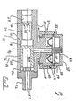
- Fig. 2 is a longitudinal cross-section view of the indicator of the invention illustrating the indicating diaphragm having a stem for protruding from an opening in the cap and illustrating the syringe-operable, one-way valve.
- Similar reference characters refer to similar parts throughout the drawings.
- The invention is defined by the appended claims with a specific embodiment shown in the attached drawings. For the purpose of summarizing the invention, the invention comprises a visual pressure indicator for endotracheal cuffs. More particularly, the indicator of the invention comprises an indicating diaphragm which is sealingly positioned within a body by means of a cap. A hole is positioned within the cap to allow protrusion of an indicating stem of the diaphragm. A fluid space, for example an air space, between the diaphragm and the body is connected in fluid communication with the cuff supply tube by means of passageways. A syringe-operable, one-way valve is positioned within the body to allow filling of the endotracheal cuff with air by means of a syringe, and to prevent leakage of the air from the cuff once it is properly filled.
- During use, the indicator of the invention is fitted to the end of the cuff supply tube, and a conventional syringe is fitted to the indicator. When the endotracheal tube is in position within the patient's trachea, the syringe is operated to force air into the endotracheal cuff via the one-way valve, cuff supply tube and cuff supply channel. The indicating diaphragm of the indicator flexes as the pressure within the cuff increases. As this pressure increases, the indicating stem of the diaphragm increasingly protrudes from the hole in the cap affixed to the body of the indicator. When the stem indicates that the cuff has been properly inflated to provide an adequate seal between it and the lumen of the trachea, the syringe is removed from the body of the indicator whereupon the one-way valve is closed to prevent any leakage of the air within the cuff to the atmosphere.
- It should be appreciated that the indicator of this invention provides an objective indication of the degree of inflation of the cuff. Should any air leak from the cuff by osmosis or should any of the anesthetic or analgetic gases leak into the cuff by osmosis, the resulting decrease or increase in pressure will be visually and objectively indicated to the anesthetist. The anesthetist may then take appropriate action to increase or decrease the pressure in the cuff by refitting the syringe to the body of the indicator and pumping more air into the cuff or releasing air from the cuff. Proper inflation of the cuff is therefore assured throughout the entire surgical procedure or emergency situation. Furthermore, all of the subjectiveness associated with the prior art devices is eliminated with the indicator of this invention.
- The foregoing has outlined rather broadly the more pertinent and important features of the present invention in order that the detailed description of the invention that follows may be better understood so that the present contribution to the art can be more fully appreciated. Additional features of the invention will be described hereinafter which form the subject of the claims of the invention.
- Fig. 1 is a detailed view illustrating the manner in which the
endotracheal cuff indicator 10 of the invention is used in conjunction with a conventional endotracheal tube, generally indicated bynumeral 12. Conventionalendotracheal tubes 12 comprise amajor tube 14 having a length of one foot (approximately 0.3 metres) or longer. A connector 16 is affixed to the proximal end of themajor tube 14 to allow connection of the anesthetist's machines to themajor tube 14. Theendotracheal tube 12 includes an inflatable device, generally known as acuff 18, at its terminal end. Acuff supply channel 20 is formed longitudinally within the wall of themajor tube 14 along its longitudinal length. A cuff supply tube 22 (cuff tube) is then connected in fluid communication with thecuff channel 20 atjunction 24. Air forced into thecuff tube 22 flows through thecuff channel 20 into thecuff 18 itself by means of opening 26. - The
endotracheal cuff indicator 10 of the invention is designed to be fitted to the end of thecuff tube 22 to allow thecuff 18 to be filled with air by means of aconventional syringe 28. - Referring now to Fig. 2, the
indicator 10 of the invention comprises a rigid body member, generally indicated bynumeral 30, having adiaphragm receiving portion 32 and avalve receiving portion 34. Adiaphragm 36 is sealingly positioned in thediaphragm receiving portion 32 of thebody 30, and acap 38 is then affixed to thediaphragm receiving portion 32 to enclose thediaphragm 36 therein. A syringe-operable,reciprocating valve member 40 is positioned in thevalve receiving portion 34 of thebody 30, and aretainer 42 is then affixed to thevalve receiving portion 34. - More specifically, the
diaphragm receiving portion 32 ofbody 30 comprises an upstanding,annular wall 44 positioned about its periphery and a centrally locatedupstanding support 46. A central passageway extends through the support into thevalve receiving portion 34 of thebody 30. Thewall 44 acts to sealingly position the diaphragm by means of the cap. - The
diaphragm 36 of theindicator 10 comprises a substantially circular design having a diameter substantially equal to the diameter formed by the upper edge of theupstanding wall 44 of thebody 30. Thediaphragm 36 further includes a centrally located,upstanding stem 50. Preferably, stem 50 and thediaphragm 36 itself are molded integrally with one another from a resilient material such as forty durometer polyvinylchloride or silicone. Also preferably,diaphragm 36 may include anannular bellow 52 integrally formed therewith to enhance the upward flexing of thediaphragm 36 without significant stretching of the resilient material. - The
cap 38 extends over at least part of the diaphragm receiving portion and is configured to sealingly secure thediaphragm 36 into position over the edge of theupstanding wall 44 of thebody 30. Preferably,cap 38 comprises an annular step 54 whose inner edge engages the outer peripheral edge of thediaphragm 36 and forces the same against the upper edge of theupstanding wall 44. The outer peripheral edge of thediaphragm 36 may include anannular protrusion 56 to enhance the ability to seal against theupstanding wall 44 by means of the pressure exerted by thecap 38. - The
cap 38 is preferably secured into position about theupstanding wall 44 of thebody 30 by means of anannular protrusion 58 which extends inwardly from thecap 38 and engages into a correspondingannular notch 60 in the bottom edge of thediaphragm receiving portion 32 of thebody 30. - The
cap 38 further includes a centrally located opening 62 aligned with the stem and having a diameter appreciably greater than the diameter of the indicatingstem 50. Preferably, thecap 38 and stem 50 are dimensioned with respect to one another in such a manner that thestem 50 does not externally protrude from opening 62 when thediaphragm 36 is in its unflexed state. Accordingly, since thestem 50 does not protrude from opening 62 during non-use, this feature assures that thestem 50 will not become damaged during shipment or storage of theindicator 10. - The
valve receiving portion 34 of thebody 30 of theindicator 10 includes a substantially cylindrical design having acentral passageway 64 therethrough. Thepassageway 64 includes a reduceddiameter portion 66 and an increaseddiameter portion 68 which together define avalve seating portion 70. The one-way valve member 40 is designed for insertion and reciprocal mounting within thepassageway 64. Thevalve member 40 is composed of neoprene, silicone, rubber or like material and comprises a corresponding reduceddiameter portion 74 and an increaseddiameter portion 76 which together define a correspondingvalve seating portion 78. The interior 40A of thevalve member 40 is hollow so that the walls of the increaseddiameter portion 76 are resilient. - During use, the
valve member 40 is inserted into thecentral passageway 64 and then secured into position by thetube adapting retainer 42. Preferably,retainer 42 is sonic welded to the wall of thevalve receiving portion 34 of thebody 30. When thevalve member 40 is retained into position in thepassageway 64, the valve seats 70 and 78 are sealingly forced together by means of a notchedfoot member 82 integrally formed with theretainer 42. Theretainer 42 includes acentral passageway 84. Fluid communication betweenpassageways 48 and 84 is assured by means of notchedchannels 86 formed within the wall of thecentral passageway 64 of thevalve receiving portion 34 and the notchedfoot member 82. - During use, the
cuff tube 14 is sealingly fitted intopassageway 84 ofretainer 42. The tip of thesyringe 28 is then fitted into the other end of theindicator 10 to engage the end 88 (terminal end) of thevalve member 40. The tip of thesyringe 28 is forced inwardly to properly seal against the edge ofpassageway 64 while appreciably moving thevalve member 40 rearwardly against the resilient force of the wall of the increaseddiameter portion 76, thereby breaking the seal between the valve seats 70 and 78 and opening thevalve 40. Thesyringe 28 is then operated to force air therefrom into thecuff 18 viapassageway 64,cuff tube 22 andcuff channel 20. Anotch 90 may be provided in the end of thevalve member 40 to assure a free flow of the air from thesyringe 28. - As the pressure within the
cuff 18 increases, it is apparent that thediaphragm 36 is caused to flex whereupon the indicatingstem 50 begins to protrude from thecap 38 viaopening 62. When thecuff 18 is properly inflated as indicated by thestem 50 extending from thecap 38, thesyringe 28 is removed from the end of thebody 30 whereuponvalve member 40 is forced forwardly again by means offoot member 82. The valve seats 70 and 78 then sealingly engage one another. - It should be appreciated that the
indicator 10 of the invention overcomes the disadvantages of the prior art devices set forth above. Specifically, it is apparent that theindicator 10 of the invention eliminates the subjectiveness associated with the prior art devices in indicating to the anesthetist when thecuff 18 of theendotracheal tube 12 has been properly inflated. In this regard, it is noted that the indicatingstem 50 may include indicia which visually indicate the proportional amount of the indicatingstem 50 extending from thecap 38 when in use.
Claims (8)
- An indicator for use in connection with an endotracheal tube (12) having a cuff (18) inflatable via a cuff tube (22), comprising in combination:
a rigid body (30) including a diaphragm receiving portion (32);
a flexible diaphragm (36) including a stem (50) positioned to provide a visual indication when the diaphragm flexes;
means for sealingly positioning said flexible diaphragm (36) within said diaphragm receiving portion (32) of said rigid body (30) of the indicator (10) to define an air space between said rigid body (30) and the diaphragm (36), said means including a cap (38) positioned over said diaphragm (36) and over at least a portion of said diaphragm receiving portion (32) to enclose the diaphragm therein, said cap including an opening (62) aligned with said stem to permit said stem (50) to protrude therefrom upon flexing of said diaphragm (36); and
means for connecting said air space in fluid communication with said cuff tube (22); characterised in that
said diaphragm (36) is arranged to be flexed freely and proportionally by pressure existing in the cuff tube (22) and, correspondingly, in the cuff (18), so that the stem (50) visually indicates the relative degree of pressure in the cuff (18). - An indicator as set forth in claim 1, wherein said diaphragm (36) comprises a bellow (52) integrally formed therewith to enhance the degree of movement of said stem (50) upon flexing of said diaphragm (36).
- An indicator as set forth in claim 1 or 2, wherein said diaphragm receiving portion comprises an upstanding wall (44) on which is sealingly positioned said diaphragm (36) by means of said cap (38).
- An indicator as set forth in claim 3, wherein said diaphragm (36) includes a protrusion (56) about its periphery to enhance the sealing engagement with said upstanding wall (44).
- An indicator as set forth in claim 2, or claim 3 or 4 as appended to claim 2, wherein said bellow (52) is of a generally annular shape.
- An indicator as set forth in any preceding claim, wherein said body member (30) is rigid.
- An indicator as set forth in any preceding claim, further comprising:
a syringe-operable, one-way valve connected in fluid communication with said cuff tube (22) at a terminal end thereof. - An indicator as set forth in claim 7, wherein said syringe-operable, one-way valve comprises in combination:
said body including a valve receiving portion (34) having a central passageway (64) therethrough;
a valve member (40) reciprocally mounted within said central passageway (64);
said central passageway (64) and said valve member (40) including seat engaging surfaces (70,78) which seal together when said valve member (40) is urged forwardly; and
means for urging said valve member (40) forwardly, whereby, upon affixing a syringe (28) to said valve receiving portion (34), said valve member (40) may be forced rearwardly to allow flowing of a fluid from the syringe (28) through said central passageway (64) into the cuff tube (22) to inflate the cuff and whereby removal of the syringe (28) from the valve receiving portion (34) permits said valve member (40) to move forwardly to prevent leakage of the fluid therefrom.
Applications Claiming Priority (1)
| Application Number | Priority Date | Filing Date | Title |
|---|---|---|---|
| US06/640,074 US4617015A (en) | 1984-08-10 | 1984-08-10 | Visual pressure indicator for endotracheal cuff |
Publications (2)
| Publication Number | Publication Date |
|---|---|
| EP0231564A1 EP0231564A1 (en) | 1987-08-12 |
| EP0231564B1 true EP0231564B1 (en) | 1991-07-31 |
Family
ID=24566751
Family Applications (1)
| Application Number | Title | Priority Date | Filing Date |
|---|---|---|---|
| EP86300750A Expired - Lifetime EP0231564B1 (en) | 1984-08-10 | 1986-02-05 | Endotracheal cuff indicator |
Country Status (3)
| Country | Link |
|---|---|
| US (1) | US4617015A (en) |
| EP (1) | EP0231564B1 (en) |
| DE (1) | DE3680658D1 (en) |
Cited By (1)
| Publication number | Priority date | Publication date | Assignee | Title |
|---|---|---|---|---|
| CN102252802A (en) * | 2011-04-25 | 2011-11-23 | 无锡沃骐医疗科技有限公司 | Pressure indication device and fluid injection equipment with same |
Families Citing this family (62)
| Publication number | Priority date | Publication date | Assignee | Title |
|---|---|---|---|---|
| US4924862A (en) * | 1987-08-19 | 1990-05-15 | Gary Levinson | Pressure controller and leak detector for tracheal tube cuff |
| US4856510A (en) * | 1988-04-06 | 1989-08-15 | Kowalewski Ryszard J | Tracheal tube inflator |
| FR2638092B1 (en) * | 1988-10-26 | 1990-12-28 | Boussignac Georges | RESPIRATORY ASSISTANCE APPARATUS |
| DE3919634A1 (en) * | 1989-06-16 | 1990-12-20 | Dimitrov Pentcho | Endotracheal tube with two inflatable balloons - has balloons connected to common air supply system |
| WO1991009643A1 (en) * | 1989-12-21 | 1991-07-11 | Medical Innovations Corporation | Ferrule and enteral tube incorporating a ferrule |
| US5235973A (en) * | 1991-05-15 | 1993-08-17 | Gary Levinson | Tracheal tube cuff inflation control and monitoring system |
| US5429582A (en) * | 1991-06-14 | 1995-07-04 | Williams; Jeffery A. | Tumor treatment |
| US5931774A (en) * | 1991-06-14 | 1999-08-03 | Proxima Therapeutics, Inc. | Inflatable devices for tumor treatment |
| US5591171A (en) * | 1991-06-14 | 1997-01-07 | Brown; Byron L. | Adapter and method for measuring pressures of fluid materials |
| US5360413A (en) * | 1991-12-06 | 1994-11-01 | Filtertek, Inc. | Needleless access device |
| US5421325A (en) * | 1992-04-30 | 1995-06-06 | Cinberg; James Z. | Endotracheal tube assembly and related method |
| US5395348A (en) * | 1993-05-04 | 1995-03-07 | Symbiosis Corporation | Medical intravenous administration line connectors |
| US5954313A (en) * | 1995-12-29 | 1999-09-21 | Rymed Technologies, Inc. | Medical intravenous administration line connectors having a luer activated valve |
| US5833213A (en) * | 1995-12-29 | 1998-11-10 | Rymed Technologies, Inc. | Multiple dose drug vial adapter for use with a vial having a pierceable septum and a needleless syringe |
| US5788215A (en) * | 1995-12-29 | 1998-08-04 | Rymed Technologies | Medical intravenous administration line connectors having a luer or pressure activated valve |
| DE69728422T2 (en) * | 1996-11-18 | 2005-03-03 | Nypro Inc., Clinton | WASHABLE LOWER VALVE |
| US6883778B1 (en) | 1996-11-18 | 2005-04-26 | Nypro Inc. | Apparatus for reducing fluid drawback through a medical valve |
| US7789864B2 (en) | 1996-11-18 | 2010-09-07 | Nypro Inc. | Luer-activated valve |
| JP2001061965A (en) * | 1999-06-25 | 2001-03-13 | Koken Co Ltd | Cuff internal pressure display |
| US6530898B1 (en) | 2000-04-20 | 2003-03-11 | Tyco Healthcare Group Lp | Visual inflation pressure indicator and surgical tube including the indicator |
| JP2003535622A (en) * | 2000-05-09 | 2003-12-02 | ユナイテッド ステーツ エンドスコピー グループ インコーポレイテッド | Barrett's esophageal cytology device |
| WO2002034326A2 (en) | 2000-10-23 | 2002-05-02 | Nypro, Inc. | Anti-drawback medical valve |
| US7108661B2 (en) * | 2001-05-07 | 2006-09-19 | United States Endoscopy Group, Inc. | Method and collection device for Barrett's esophagus cells |
| JP2005500142A (en) | 2001-08-22 | 2005-01-06 | ナイプロ・インク | Medical valve with expansion member |
| US7753892B2 (en) | 2001-11-13 | 2010-07-13 | Nypro Inc. | Anti-drawback medical valve |
| US6869426B2 (en) | 2001-11-13 | 2005-03-22 | Nypro Inc. | Anti-drawback medical valve |
| US7837658B2 (en) | 2001-11-13 | 2010-11-23 | Nypro Inc. | Anti-drawback medical valve |
| US7357792B2 (en) | 2002-10-29 | 2008-04-15 | Nypro Inc. | Positive push medical valve with internal seal |
| US7914502B2 (en) | 2003-07-31 | 2011-03-29 | Nypro Inc. | Anti-drawback medical valve |
| US20050267415A1 (en) * | 2004-05-14 | 2005-12-01 | C. R. Bard, Inc. | Medical devices and methods of use |
| JP5102023B2 (en) * | 2004-06-29 | 2012-12-19 | シー アール バード インコーポレイテッド | Method and system for fluid communication with a gastrostomy tube |
| US7404329B2 (en) * | 2004-12-08 | 2008-07-29 | Engineered Medical Systems, Inc. | Pressure gauge for use with an airway lumen |
| US7887519B2 (en) | 2005-01-14 | 2011-02-15 | Nypro Inc. | Valve with internal lifter |
| US9579477B2 (en) | 2005-12-27 | 2017-02-28 | Hansa Medical Products, Inc. | Endotracheal tube having outer and inner cannulae |
| US8707956B2 (en) | 2005-12-27 | 2014-04-29 | Hansa Medical Products, Inc. | Endotracheal tube having outer and inner cannulae |
| WO2007124167A2 (en) * | 2006-04-21 | 2007-11-01 | C. R. Bard, Inc. | Feeding device and bolster apparatus and method for making the same |
| US8100869B2 (en) | 2006-08-11 | 2012-01-24 | Nypro Inc. | Medical valve with expandable member |
| US8307830B2 (en) | 2006-09-29 | 2012-11-13 | Nellcor Puritan Bennett Llc | Endotracheal cuff and technique for using the same |
| JP2009119012A (en) * | 2007-11-14 | 2009-06-04 | Advanex Inc | Indicator for medical device with cuff |
| US20090301474A1 (en) | 2008-06-05 | 2009-12-10 | Neil Alex Korneff | Heat and moisture exchange unit with resistance indicator |
| US10271716B2 (en) * | 2008-06-27 | 2019-04-30 | C.R. Bard, Inc. | Endoscopic vacuum controller |
| US8905029B2 (en) * | 2008-09-29 | 2014-12-09 | Covidien Lp | Airway system with carbon dioxide sensor for determining tracheal cuff inflation and technique for using the same |
| DE102008052438A1 (en) | 2008-10-21 | 2010-04-22 | Willy Rüsch GmbH | tracheal tube |
| JP2012515064A (en) * | 2009-01-15 | 2012-07-05 | ベス・イスラエル・デイーコネス・メデイカル・センター | Pressure measuring syringe |
| ES2696987T3 (en) | 2009-06-22 | 2019-01-21 | Np Medical Inc | Medical valve with improved backpressure seal |
| US8844534B2 (en) * | 2009-06-30 | 2014-09-30 | Covidien Lp | Tracheal tube with lumen for tracheal pressure measurement and technique for using the same |
| US8715244B2 (en) * | 2009-07-07 | 2014-05-06 | C. R. Bard, Inc. | Extensible internal bolster for a medical device |
| US9528897B2 (en) * | 2009-08-13 | 2016-12-27 | Chimden Medical Pty Ltd | Pressure indicator |
| JP2013518697A (en) * | 2010-02-09 | 2013-05-23 | シー・アール・バード・インコーポレーテッド | Contraction indicator for medical device bolster |
| US8550078B2 (en) * | 2010-03-10 | 2013-10-08 | Seedlings Life Science Ventures, Llc. | Inflation and monitoring assembly for a pressure cuff of an endotracheal tube |
| WO2011133537A1 (en) * | 2010-04-20 | 2011-10-27 | Walter Levine | Inflatable respiratory cuff with pressure relief valve |
| US9138572B2 (en) | 2010-06-24 | 2015-09-22 | Np Medical Inc. | Medical valve with fluid volume alteration |
| US10549054B2 (en) | 2011-02-02 | 2020-02-04 | Teleflex Life Sciences Unlimited Company | Artificial airway |
| US9180268B2 (en) | 2012-05-01 | 2015-11-10 | Covidien Lp | Cuff pressure measurement device for a tracheal tube |
| AU2013201131B2 (en) * | 2012-12-03 | 2015-02-19 | Hansa Medical Products, Inc. | Endotracheal tube having outer and inner cannulae |
| US10493226B2 (en) | 2013-03-15 | 2019-12-03 | Seedlings Life Science Ventures, Llc | System and assembly for inflating and monitoring pressure within a retaining cuff |
| CN108096675B (en) * | 2018-01-31 | 2023-10-20 | 重庆医科大学 | Artificial airway leakage alarm |
| US11219729B2 (en) | 2018-03-21 | 2022-01-11 | Hansa Medical Products, Inc. | Medical device system and method including an endotracheal tube |
| WO2019186230A1 (en) * | 2018-03-26 | 2019-10-03 | Velez Rivera Hector De Jesus | Pressure regulator for verifying the inflation of balloons of endotracheal cannulas or tubes |
| WO2020236613A1 (en) * | 2019-05-17 | 2020-11-26 | PAVmed Inc. | A catheter device system and method of use |
| USD910853S1 (en) | 2019-05-29 | 2021-02-16 | Covidien Lp | Cuff pressure regulator |
| CN112156306B (en) * | 2020-09-10 | 2023-03-21 | 西安交通大学 | Trachea cannula for monitoring cuff pressure in real time |
Family Cites Families (10)
| Publication number | Priority date | Publication date | Assignee | Title |
|---|---|---|---|---|
| US3409015A (en) * | 1965-04-01 | 1968-11-05 | Davol Inc | Balloon catheter having an integral self-sealing inflation valve |
| US3656482A (en) * | 1970-01-19 | 1972-04-18 | Joseph Sunnen | Applicator for dispensing substances |
| US3688794A (en) * | 1970-08-10 | 1972-09-05 | Bird F M | Exhalation valve for respirator |
| FR2257311A1 (en) * | 1974-01-14 | 1975-08-08 | Jackson Richard | Endotracheal tube with liquid fillable cuff - mfd from air permeable expanded hydrophobic cellular plastics, pref. PTFE |
| US4143616A (en) * | 1977-03-18 | 1979-03-13 | Robertshaw Controls Company | Process machinery control system and individual safety control systems therefor or the like |
| US4182344A (en) * | 1977-08-19 | 1980-01-08 | G. D. Searle & Co., Limited | Pressure control tracheal device |
| DE2803094A1 (en) * | 1978-01-25 | 1979-07-26 | Hoechst Ag | TRACHEAL TUBE WITH PRESSURE VALVE |
| US4370982A (en) * | 1980-09-10 | 1983-02-01 | Medrad, Inc. | Method and apparatus for injecting and for controlling the pressure of fluid being injected into a catheter |
| US4361107A (en) * | 1980-11-20 | 1982-11-30 | Gereg Gordon A | Overinflation indicator for tracheal tubes |
| DE3321155C2 (en) * | 1983-06-11 | 1985-10-24 | Dietrich Dr.Med. Inthorn | Control device for tube cuff pressure |
-
1984
- 1984-08-10 US US06/640,074 patent/US4617015A/en not_active Expired - Lifetime
-
1986
- 1986-02-05 DE DE86300750T patent/DE3680658D1/en not_active Expired - Lifetime
- 1986-02-05 EP EP86300750A patent/EP0231564B1/en not_active Expired - Lifetime
Cited By (1)
| Publication number | Priority date | Publication date | Assignee | Title |
|---|---|---|---|---|
| CN102252802A (en) * | 2011-04-25 | 2011-11-23 | 无锡沃骐医疗科技有限公司 | Pressure indication device and fluid injection equipment with same |
Also Published As
| Publication number | Publication date |
|---|---|
| US4617015A (en) | 1986-10-14 |
| EP0231564A1 (en) | 1987-08-12 |
| DE3680658D1 (en) | 1991-09-05 |
Similar Documents
| Publication | Publication Date | Title |
|---|---|---|
| US4617015A (en) | Visual pressure indicator for endotracheal cuff | |
| US3731691A (en) | Endotracheal tube and connector unit | |
| US6860264B2 (en) | Method and apparatus for endotracheal intubation using a light wand and curved guide | |
| US4041936A (en) | Bronchoscopy tube | |
| US6021779A (en) | Laryngeal mask airways and their manufacture | |
| US6536437B1 (en) | Cuffed nasal airway and anesthetic wand system | |
| US4649913A (en) | Tracheostomy tube assemblies | |
| US4416273A (en) | Connector valve assembly for endotracheal tubes | |
| US5591130A (en) | Esophageal intubation detector with indicator | |
| US6629530B2 (en) | Single-element sealing valve for a respiratory support system | |
| US4498473A (en) | Variable stiffness tracheal tube | |
| US4898168A (en) | Inflation indicators for cuffed tubes | |
| US6513527B1 (en) | Bibronchial double lumen tube | |
| US20080210235A1 (en) | Intubation detector | |
| US7938118B2 (en) | Combination laryngeal mask airway with dual blocking and fluid removal features and method | |
| EP0489516A1 (en) | Pressure monitors and tube assemblies | |
| US7077135B2 (en) | Resuscitators, parts and assemblies | |
| EP3222315A1 (en) | Device and method for pressure indication | |
| US20030192548A1 (en) | Laryngeal mask airway | |
| CA1064358A (en) | Cuff inflation for tracheal tubes | |
| Carroll et al. | Performance characteristics of tracheal cuffs | |
| US4248222A (en) | Endotracheal tube having a relief valve | |
| US20180369526A1 (en) | Airway Suction Inlet Port | |
| US20190009042A1 (en) | Cuff inflators, indicators and assemblies | |
| WO1993024170A1 (en) | Intubation devices |
Legal Events
| Date | Code | Title | Description |
|---|---|---|---|
| PUAI | Public reference made under article 153(3) epc to a published international application that has entered the european phase |
Free format text: ORIGINAL CODE: 0009012 |
|
| AK | Designated contracting states |
Kind code of ref document: A1 Designated state(s): AT BE CH DE FR GB IT LI LU NL SE |
|
| 17P | Request for examination filed |
Effective date: 19880122 |
|
| 17Q | First examination report despatched |
Effective date: 19890713 |
|
| GRAA | (expected) grant |
Free format text: ORIGINAL CODE: 0009210 |
|
| AK | Designated contracting states |
Kind code of ref document: B1 Designated state(s): DE GB |
|
| REF | Corresponds to: |
Ref document number: 3680658 Country of ref document: DE Date of ref document: 19910905 |
|
| EN | Fr: translation not filed | ||
| PLBE | No opposition filed within time limit |
Free format text: ORIGINAL CODE: 0009261 |
|
| STAA | Information on the status of an ep patent application or granted ep patent |
Free format text: STATUS: NO OPPOSITION FILED WITHIN TIME LIMIT |
|
| 26N | No opposition filed | ||
| PGFP | Annual fee paid to national office [announced via postgrant information from national office to epo] |
Ref country code: GB Payment date: 19940111 Year of fee payment: 9 |
|
| PGFP | Annual fee paid to national office [announced via postgrant information from national office to epo] |
Ref country code: DE Payment date: 19940224 Year of fee payment: 9 |
|
| PG25 | Lapsed in a contracting state [announced via postgrant information from national office to epo] |
Ref country code: GB Effective date: 19950205 |
|
| GBPC | Gb: european patent ceased through non-payment of renewal fee |
Effective date: 19950205 |
|
| PG25 | Lapsed in a contracting state [announced via postgrant information from national office to epo] |
Ref country code: DE Effective date: 19951101 |